EP0990096B1 - Poids sur la roue permettant d'equilibrer la roue d'un vehicule - Google Patents
Poids sur la roue permettant d'equilibrer la roue d'un vehicule Download PDFInfo
- Publication number
- EP0990096B1 EP0990096B1 EP98921667A EP98921667A EP0990096B1 EP 0990096 B1 EP0990096 B1 EP 0990096B1 EP 98921667 A EP98921667 A EP 98921667A EP 98921667 A EP98921667 A EP 98921667A EP 0990096 B1 EP0990096 B1 EP 0990096B1
- Authority
- EP
- European Patent Office
- Prior art keywords
- wheel
- weight
- rim
- joining surface
- profile
- Prior art date
- Legal status (The legal status is an assumption and is not a legal conclusion. Google has not performed a legal analysis and makes no representation as to the accuracy of the status listed.)
- Expired - Lifetime
Links
- 238000005304 joining Methods 0.000 claims description 27
- 239000012790 adhesive layer Substances 0.000 claims description 14
- 239000011521 glass Substances 0.000 claims description 7
- 238000005554 pickling Methods 0.000 claims description 3
- 238000005488 sandblasting Methods 0.000 claims description 3
- 239000002253 acid Substances 0.000 claims description 2
- 239000000463 material Substances 0.000 description 16
- 239000000853 adhesive Substances 0.000 description 14
- 230000001070 adhesive effect Effects 0.000 description 14
- VYPSYNLAJGMNEJ-UHFFFAOYSA-N Silicium dioxide Chemical compound O=[Si]=O VYPSYNLAJGMNEJ-UHFFFAOYSA-N 0.000 description 6
- 239000000919 ceramic Substances 0.000 description 5
- 238000004519 manufacturing process Methods 0.000 description 5
- 238000000465 moulding Methods 0.000 description 4
- 239000004115 Sodium Silicate Substances 0.000 description 3
- 230000009931 harmful effect Effects 0.000 description 3
- 239000000377 silicon dioxide Substances 0.000 description 3
- NTHWMYGWWRZVTN-UHFFFAOYSA-N sodium silicate Chemical compound [Na+].[Na+].[O-][Si]([O-])=O NTHWMYGWWRZVTN-UHFFFAOYSA-N 0.000 description 3
- 229910052911 sodium silicate Inorganic materials 0.000 description 3
- UQSXHKLRYXJYBZ-UHFFFAOYSA-N Iron oxide Chemical compound [Fe]=O UQSXHKLRYXJYBZ-UHFFFAOYSA-N 0.000 description 2
- 229910000831 Steel Inorganic materials 0.000 description 2
- 239000000378 calcium silicate Substances 0.000 description 2
- 229910052918 calcium silicate Inorganic materials 0.000 description 2
- OYACROKNLOSFPA-UHFFFAOYSA-N calcium;dioxido(oxo)silane Chemical compound [Ca+2].[O-][Si]([O-])=O OYACROKNLOSFPA-UHFFFAOYSA-N 0.000 description 2
- 238000001816 cooling Methods 0.000 description 2
- 239000000203 mixture Substances 0.000 description 2
- 235000012239 silicon dioxide Nutrition 0.000 description 2
- 239000010959 steel Substances 0.000 description 2
- 239000002699 waste material Substances 0.000 description 2
- 229910000838 Al alloy Inorganic materials 0.000 description 1
- 229910045601 alloy Inorganic materials 0.000 description 1
- 239000000956 alloy Substances 0.000 description 1
- 238000006243 chemical reaction Methods 0.000 description 1
- 239000003795 chemical substances by application Substances 0.000 description 1
- 238000004040 coloring Methods 0.000 description 1
- 238000005520 cutting process Methods 0.000 description 1
- 230000000254 damaging effect Effects 0.000 description 1
- 238000005034 decoration Methods 0.000 description 1
- 230000002939 deleterious effect Effects 0.000 description 1
- 230000001419 dependent effect Effects 0.000 description 1
- 238000011161 development Methods 0.000 description 1
- 230000018109 developmental process Effects 0.000 description 1
- 230000003670 easy-to-clean Effects 0.000 description 1
- 230000000694 effects Effects 0.000 description 1
- 230000002349 favourable effect Effects 0.000 description 1
- 229910001385 heavy metal Inorganic materials 0.000 description 1
- 239000010410 layer Substances 0.000 description 1
- 239000007788 liquid Substances 0.000 description 1
- 229910052751 metal Inorganic materials 0.000 description 1
- 239000002184 metal Substances 0.000 description 1
- 229910001092 metal group alloy Inorganic materials 0.000 description 1
- 229910052914 metal silicate Inorganic materials 0.000 description 1
- 239000000843 powder Substances 0.000 description 1
- 238000010437 sandpainting Methods 0.000 description 1
- 239000000779 smoke Substances 0.000 description 1
- 238000007711 solidification Methods 0.000 description 1
- 230000008023 solidification Effects 0.000 description 1
- 239000005315 stained glass Substances 0.000 description 1
- XLYOFNOQVPJJNP-UHFFFAOYSA-N water Substances O XLYOFNOQVPJJNP-UHFFFAOYSA-N 0.000 description 1
Images


Classifications
-
- F—MECHANICAL ENGINEERING; LIGHTING; HEATING; WEAPONS; BLASTING
- F16—ENGINEERING ELEMENTS AND UNITS; GENERAL MEASURES FOR PRODUCING AND MAINTAINING EFFECTIVE FUNCTIONING OF MACHINES OR INSTALLATIONS; THERMAL INSULATION IN GENERAL
- F16F—SPRINGS; SHOCK-ABSORBERS; MEANS FOR DAMPING VIBRATION
- F16F15/00—Suppression of vibrations in systems; Means or arrangements for avoiding or reducing out-of-balance forces, e.g. due to motion
- F16F15/10—Suppression of vibrations in rotating systems by making use of members moving with the system
- F16F15/12—Suppression of vibrations in rotating systems by making use of members moving with the system using elastic members or friction-damping members, e.g. between a rotating shaft and a gyratory mass mounted thereon
-
- F—MECHANICAL ENGINEERING; LIGHTING; HEATING; WEAPONS; BLASTING
- F16—ENGINEERING ELEMENTS AND UNITS; GENERAL MEASURES FOR PRODUCING AND MAINTAINING EFFECTIVE FUNCTIONING OF MACHINES OR INSTALLATIONS; THERMAL INSULATION IN GENERAL
- F16F—SPRINGS; SHOCK-ABSORBERS; MEANS FOR DAMPING VIBRATION
- F16F15/00—Suppression of vibrations in systems; Means or arrangements for avoiding or reducing out-of-balance forces, e.g. due to motion
- F16F15/32—Correcting- or balancing-weights or equivalent means for balancing rotating bodies, e.g. vehicle wheels
- F16F15/324—Correcting- or balancing-weights or equivalent means for balancing rotating bodies, e.g. vehicle wheels the rotating body being a vehicle wheel
- F16F15/328—Multiple weights on adhesive strip
-
- F—MECHANICAL ENGINEERING; LIGHTING; HEATING; WEAPONS; BLASTING
- F16—ENGINEERING ELEMENTS AND UNITS; GENERAL MEASURES FOR PRODUCING AND MAINTAINING EFFECTIVE FUNCTIONING OF MACHINES OR INSTALLATIONS; THERMAL INSULATION IN GENERAL
- F16F—SPRINGS; SHOCK-ABSORBERS; MEANS FOR DAMPING VIBRATION
- F16F15/00—Suppression of vibrations in systems; Means or arrangements for avoiding or reducing out-of-balance forces, e.g. due to motion
- F16F15/32—Correcting- or balancing-weights or equivalent means for balancing rotating bodies, e.g. vehicle wheels
- F16F15/34—Fastening arrangements therefor
-
- F—MECHANICAL ENGINEERING; LIGHTING; HEATING; WEAPONS; BLASTING
- F16—ENGINEERING ELEMENTS AND UNITS; GENERAL MEASURES FOR PRODUCING AND MAINTAINING EFFECTIVE FUNCTIONING OF MACHINES OR INSTALLATIONS; THERMAL INSULATION IN GENERAL
- F16F—SPRINGS; SHOCK-ABSORBERS; MEANS FOR DAMPING VIBRATION
- F16F2224/00—Materials; Material properties
Definitions
- the present invention discloses a wheel-weight to be mounted on a vehicle wheel to balance it and possessing a rigid body and a joining surface on the rigid body that can be fitted to a surface of a wheel rim.
- wheel-weights for balancing vehicle wheels. It is well known that the primary consideration when forming wheel-weights for balancing vehicle wheels is that the wheel-weight is to be mounted point-like on the wheel rim and in a way that it is not visible.
- the material of the wheel-weight is chosen in a way that the largest weight should be concentrated in the smallest possible volume, and the shape of the wheel-weight is chosen to fit tight to the wheel rim as much as possible so that it is difficult to notice it.
- the material of the wheel-weights is chosen to be heavy metal, usually lead or some alloy of high lead content, as it is described e.g. in USA patent specification No. 4.300.803.
- One type of wheel-weight, to be used with wheel rims made from either steel plate or light metal alloy, usually aluminium alloy, are box shaped with relatively small height, having a rectangle shaped base surface as a joining surface and can be stick by adhesive on the inner surface of the wheel rim facing the axle, as one of them is described in USA patent specification No. 3.960.409.
- the other type of 'wheel-weight frequently used in case of wheel rims made from steel plate are crescent-shaped and fitted into the groove near the rim of the wheel rim, the joining surface of the wheel-weight is curved both in the longitudinal and the transversal directions following the arc of the rim and the profile of the groove and can be fixed to the rim via sticking or with elastic clips or springs.
- This kind of wheel-weights are described e.g. in German patent specification No. 1.816.669 and U.S. patent specifications No. 2.548.842, 3.890.008 and 4.300.803. In all these cases the text-surface containing the data relating to the wheel-weight is formed on the surface of the body of the wheel-weight reverse to the joining surface.
- DE-A-3 637 256 discloses a rotor as part of a piece of equipment comprising a rotor body connected rigidly to a shaft.
- the rotor body is manufactured from ceramic and can be balanced. Balancing is accomplished by attaching or removing balance weights to the rotor body. Therefore the rotor body has cut-outs for the fitting of balance weights and furthermore has integrally formed balance weights which can be removed, at least in part.
- US-A-5 151 325 discloses ceramic turbine wheels which are balanced to minimize rotational vibrations by bonding silica-based glass pads to the wheel.
- the pads are formed from a mixture of sodium silicate, water and a fine ceramic powder, preferably of a composition similar to the underlying ceramic turbine wheel. The weighted pads are machined, without damage to the underlying ceramic wheel, to achieve proper balance.
- the fundamental idea of the invention is that instead of the practice of applying the largest weight concentrated in the smallest possible volume, the wheel-weight of the desired weight can be realised even if it is made of some appropriate material other than lead. As a result of the fact that the material of the wheel-weight is different from lead, the wheel-weight has a plenty of advantages compensating for the larger volume.
- the wheel-weight according to the invention comprises a rigid body which is made of glass.
- the shape of the wheel-weight according to the invention is the known box shape with rounded edges and corners, or crescent shape, or other, e.g. a shape similar to the egg like shape of a prolate ellipsoid, or a symmetrical pebble, or a shape chosen to meet the actual demand and requirement.
- An extended surface of these forms is the joining surface.
- the other surfaces of the wheel-weight are indifferent, favourably determined by the manufacturing method.
- the usual components such as silicon dioxide, components containing sodium silicate and/or calcium silicate, or some metal silicate components replacing partly or entirely any or several of these components, and further components if required, are melt on the usual way, the resulting melt is formed to the shape of the wheel-weight and cooled in stress-free circumstances.
- the joining surface of the wheel-weight is formed with the open or closed moulding tool, whereas the other surfaces are determined by the moulding tool in case if using a closed moulding tool, while in case of using an open moulding tool the other surfaces are natural surfaces formed in the course of the solidification determined by the internal viscosity and the cooling rate.
- the rigid body of the wheel-weight made of glass can be transparent or coloured, its colour can be chosen on demand, preferably chosen to match the colour of the vehicle wheel, it may be unicoloured, multicoloured or transparent, there may be patterns on it, preferably coloured longitudinal lines or concentric circles.
- the desired colour is preferably ensured by mixing the appropriate colouring agent to the basic components.
- the wheel-weight according to the invention can be fashioned to be fixed via sticking.
- the joining surface of this embodiment is supplied with an adhesive layer.
- the adhesive layer of the wheel-weight is an adhesive material suitable for sticking glass to painted metal surfaces, e.g. some acrilate derivatives.
- the adhesive material is applied to two sides of a base sheet, this base sheet is mounted on the joining surface via the adhesive layer on the one side, the adhesive layer on the other side is used for fixing the wheel-weight on the wheel rim when applying the wheel-weight.
- the adhesive layer on the other side is conveniently covered with a protecting sheet or protecting paper, which sheet or paper is removed before using the wheel-weight.
- the adhesive material is applied to the joining surface as one layer, or it is applied to the joining surface when the wheel-weight is used.
- the wheel-weight can be fixed with liquid adhesive material as well, in this case the joining surface is covered with the adhesive material just before using the wheel-weight.
- the wheel-weight according to the invention can be fixed with the usual elastic clips or springs as well. This way of fixing is especially preferable in case of the crescent-shaped wheel-weight, the joining surface of which is suitable to be fixed in the groove of the rim flange of the wheel rim.
- These embodiments appropriately possess a clip positioning surface on the surface reverse to the joining surface.
- the positioning surface is appropriately the surface of a hollow fashioned in order to direct the clip, or the surface of the nest fixing the end of the clip.
- the wheel-weight When mounting the wheel-weight on the wheel rim the wheel-weight is fitted into the groove formed by the bent end of the rim of the wheel rim, and the clip, pressed to the outer surface of the rim, is pushed over the wheel-weight in a way that it fixes the wheel-weight elastically in the groove.
- the surface of the wheel-weight is a micro-roughened surface.
- the micro-roughened surface is properly prepared via pickling it with acid or via sand-blasting. This is favourable from the aesthetic point of view.
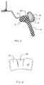
- Figure 1 shows a part of a vehicle wheel carrying a wheel-weight (10).
- the vehicle wheel contains a wheel disc (1) and a wheel rim (3) forming one unit, the wheel-weight (10) is mounted on the inner side of the wheel rim (3) facing the axle.
- the wheel-weight (10) presented here has a shape similar to an ellipsoid.
- Figure 2 shows the plane section of the wheel rim (3) with the wheel-weight (10) on it from the direction indicated on Figure 1.
- a "S" shape in the profile of the wheel rim (3) is clearly seen.
- a joining surface (13) is formed on the rigid body (11) of the wheel-weight (10), the joining surface (13) fits into the shoulder formed by the "S" shape of the profile of the wheel band (3).
- the material of the wheel-weight (10) presented as an example is usual transparent glass made of sodium silicate, calcium silicate and silicon dioxide, or green coloured glass containing a small amount of iron oxide.
- Figure 3 shows a part of the wheel rim (3) with the tyre and the wheel-weight (10) mounted on it. It is a plane section of the profile of the wheel rim (3) obtained by cutting the wheel band (3) with a plane fitting to the axis of rotation. A weld (2) fixing the wheel rim (3) to the wheel disc (1) is clearly seen.
- the rim-bed (4) of the wheel rim (3) joins to the band-shoulder (5) in a longish, first "S" shaped profile, the wheel-weight (10) is fixed to the inner side (in the radial sense) of the shoulder formed at the junction, while the thick edge (9) of the tyre (8) fits to the outer surface and the bent rim of the band-shoulder (5) near the edge of the wheel rim (3).
- the rigid body (11) of the wheel-weight (10) has a joining surface (13) fitting into the type one "S" profile, the joining surface (13) is supplied with adhesive layer (15).
- the wheel-weight (10) is fixed into the proper bend of the "S" profile of the wheel rim (3) with this adhesive layer (15).
- Figure 4 shows a part of the wheel rim (3) of a second profile with the tyre (8) and the wheel-weight (10) mounted on it.
- the rim bed (4) and the rim shoulder (5) of the wheel rim (3) connected firmly to the wheel disc (1) in the weld (2) are connected to each other in a second "S" profile providing higher rigidity.
- the joining surface (13) of the rigid body (11) of the wheel-weight (10) is formed to fit into this type of profile, and it is fixed on the above mentioned way via the adhesive layer (15).
- the arrangement of thick edge (9) of the tyre (8) is also shown on the figure.
- Figure 5 shows a part of the wheel rim of the second profile with the wheel-weight (10') mounted on it.
- the edge (6) of the rim shoulder (5) of the wheel rim (3) supporting the thick edge (9) of the tyre (8) is bent so that it forms a groove (7).
- the wheel-weight (10') of this implementation example is fixed in the groove (7) pressed in with the "C" shaped elastic clip (16).
- Figure 6 shows a part of the upper surface (17) of the wheel-weight (10') mountable with a clip.
- This embodiment possesses a positioning surface (19) deepened in the upper surface (17), the width of the positioning surface (19) corresponds to the width of the clip (16), preventing the clip (16) from slipping sideways on the wheel-weight (10') in the closed position.
- Figure 7 shows a perspective view of wheel-weight (10'') fixable with an elastic clip.
- the wheel-weight (10'') has a convexed joining surface (13') able to fit into the "S" profile of a wheel rim.
- Figure 8 shows a perspective view of a wheel-weight (10''') with convexed joining surface (13'') which is able to fit into the "S" profile of a wheel rim.
- the wheel-weight (10''') is fixable with adhesive which covers its joining surface (13'').
- Figure 9 shows a perspective view of an other type of shape of wheel-weight (100). Its joining surface (130) is convexed and covered by an adhesive layer (150).
- Figure 10 shows a'perspective view of a further type of a wheel-weight(101).
- the wheel-weight (101) having desired weight is assembled by unit wheel-weights (24,25,26) which are arranged in line and fixed by adhesive (21) on the upper side of base sheet (20) .
- the adhesive layer (22) is covered with a removable sheet (23) to protect the adhesive.
- the text surface containing the weight and other required data of the wheel-weight according to the invention can be formed on the surface of the wheel-weight reverse to the joining surface, and the text can be written on it via pickling, sand-blasting or painting.
- the major advantage of the wheel-weights according to the invention is that owing to the material they are made of, they have no harmful effect on the health and no environment polluting effect either when'being manufactured, or when being used or when becoming waste.
- a further advantage is that they are essentially like, and they behave like the natural objects that can be found in nature.
- a further advantage is that they are aesthetic, the colour and the shape of them can be chosen to fit to the wheel disc, they are appropriate to call attention as well, and they can also be applied as decoration.
- Another great advantage is that it is easy to clean them, they do not corrode, and do not enter into any chemical reactions with the materials that can be found on the wheel disc.
- a further advantage is, that as a consequence of its relatively large body standing out from the surface of the wheel disc it causes additional turbulence at the wheel disc when the car is moving, increasing this way the air cooling of the wheel disc and the tyre.
Landscapes
- Engineering & Computer Science (AREA)
- General Engineering & Computer Science (AREA)
- Physics & Mathematics (AREA)
- Acoustics & Sound (AREA)
- Aviation & Aerospace Engineering (AREA)
- Mechanical Engineering (AREA)
- Tires In General (AREA)
- Toys (AREA)
- Testing Of Balance (AREA)
Claims (5)
- Poids de roue prévue d'être montée sur une roue de véhicule pour équilibrer celle-ci, présentant un corps rigide (11) et une surface de jonction (13) sur le corps rigide (11) susceptible d'être montée sur une surface d'un bord (3) de roue,
caractérisée en ce que
le corps rigide (11) est réalisé en verre. - Poids de roue selon la revendication 1,
caractérisée en ce que
sur la surface de jonction (13), une couche adhésive (15) est appliquée. - Poids de roue selon la revendication 1 ou 2,
caractérisée en ce que
sur la surface opposée à la surface de jonction (13), une couche de positionnement de clip (19) est prévue. - Poids de roue selon la revendication 1 ou 2,
caractérisée en ce que
sa surface est rendue rugueuse grâce à un décapage à l'acide. - Poids de roue selon la revendication 1 ou 2,
caractérisée en ce que
a surface est rendue rugueuse grâce à un décapage au sable.
Applications Claiming Priority (3)
| Application Number | Priority Date | Filing Date | Title |
|---|---|---|---|
| HU9701106A HU223041B1 (hu) | 1997-06-27 | 1997-06-27 | Keréksúly gépjárműkerék kiegyensúlyozásához |
| HU1100006 | 1997-06-27 | ||
| PCT/HU1998/000036 WO1999000609A1 (fr) | 1997-06-27 | 1998-05-28 | Poids sur la roue permettant d'equilibrer la roue d'un vehicule |
Publications (2)
| Publication Number | Publication Date |
|---|---|
| EP0990096A1 EP0990096A1 (fr) | 2000-04-05 |
| EP0990096B1 true EP0990096B1 (fr) | 2005-04-13 |
Family
ID=89995292
Family Applications (1)
| Application Number | Title | Priority Date | Filing Date |
|---|---|---|---|
| EP98921667A Expired - Lifetime EP0990096B1 (fr) | 1997-06-27 | 1998-05-28 | Poids sur la roue permettant d'equilibrer la roue d'un vehicule |
Country Status (5)
| Country | Link |
|---|---|
| EP (1) | EP0990096B1 (fr) |
| AU (1) | AU7444598A (fr) |
| DE (1) | DE69829751T2 (fr) |
| HU (1) | HU223041B1 (fr) |
| WO (1) | WO1999000609A1 (fr) |
Cited By (1)
| Publication number | Priority date | Publication date | Assignee | Title |
|---|---|---|---|---|
| NL1031510C2 (nl) | 2006-04-04 | 2007-10-05 | Fastron B V | Werkwijze en matrijzen voor het vervaardigen van een inrichting voor het balanceren van een voertuigwiel, tevens zo een inrichting. |
Families Citing this family (12)
| Publication number | Priority date | Publication date | Assignee | Title |
|---|---|---|---|---|
| EP1067310B1 (fr) * | 1999-07-07 | 2004-02-25 | Topy Kogyo Kabushiki Kaisha | Masse d'équilibrage pour roue de véhicule |
| GB0020684D0 (en) * | 2000-08-23 | 2000-10-11 | Bw Mfg Ltd | Balance weight assembly |
| JP2002295592A (ja) * | 2001-04-03 | 2002-10-09 | Toho Kogyo Kk | ホイールバランスウェイト |
| WO2004090495A2 (fr) * | 2003-04-11 | 2004-10-21 | Franken Industrie Werke Ernst Stenz Gmbh & Co.Kg | Masselotte d'equilibrage pour roues de vehicule comportant une face d'appui a courbure concave ou convexe, et son procede de production |
| DE102010008657A1 (de) | 2010-02-20 | 2011-08-25 | Fischer, Erika, 73235 | Keramisches Auswuchtgewicht |
| US20130224449A1 (en) * | 2012-02-29 | 2013-08-29 | Perfect Equipment Inc. | Adhesive Balancing Weight With Adhesive Tape System |
| EP2988017B1 (fr) | 2014-08-21 | 2016-12-21 | WEGMANN automotive GmbH & Co. KG | Poids d'équilibrage auto-adhésif fendu pour une roue de véhicule |
| EP2988018A1 (fr) * | 2014-08-21 | 2016-02-24 | WEGMANN automotive GmbH & Co. KG | Poids d'équilibrage auto-adhésif pour une roue de véhicule |
| EP3203110B1 (fr) | 2016-02-02 | 2018-09-26 | WEGMANN automotive GmbH & Co. KG | Poids d'équilibrage auto-adhésif pour une roue de véhicule |
| RU2720752C2 (ru) * | 2016-02-19 | 2020-05-13 | Вегманн Отомоутив Гмбх Унд Ко. Кг | Самоклеящийся балансировочный грузик для колеса транспортного средства |
| US10060505B2 (en) * | 2016-03-11 | 2018-08-28 | Dana Automotive Systems Group, Llc | Device for securing balancing weights to a shaft |
| EP4075016A1 (fr) | 2021-04-13 | 2022-10-19 | WEGMANN automotive GmbH | Poids d'équilibrage auto-adhésif pour différentes géométries de jante |
Family Cites Families (6)
| Publication number | Priority date | Publication date | Assignee | Title |
|---|---|---|---|---|
| DE1816669A1 (de) * | 1968-12-23 | 1970-07-09 | Dionys Hofmann Maschinenfabrik | Ausgleichsgewicht fuer Kraftfahrzeugraeder,insbesondere LKW-Raeder |
| US4300803A (en) | 1979-09-14 | 1981-11-17 | Plumbium Manufacturing Corporation | Adhesive vehicle wheel weight and method |
| DE3637256A1 (de) * | 1986-11-03 | 1988-05-11 | Bbc Brown Boveri & Cie | Rotor |
| US5151325A (en) * | 1989-05-26 | 1992-09-29 | Allied-Signal Inc. | Method of dynamically balancing ceramic turbine wheels |
| US5564792A (en) * | 1994-12-13 | 1996-10-15 | Hayes Wheels International, Inc. | Balancing weight attachment system for a vehicle wheel |
| US5564791A (en) * | 1995-06-06 | 1996-10-15 | Lacks Industries, Inc. | Wheel and overlay assembly to accommodate balance weights |
-
1997
- 1997-06-27 HU HU9701106A patent/HU223041B1/hu not_active IP Right Cessation
-
1998
- 1998-05-28 DE DE69829751T patent/DE69829751T2/de not_active Expired - Fee Related
- 1998-05-28 WO PCT/HU1998/000036 patent/WO1999000609A1/fr not_active Ceased
- 1998-05-28 AU AU74445/98A patent/AU7444598A/en not_active Abandoned
- 1998-05-28 EP EP98921667A patent/EP0990096B1/fr not_active Expired - Lifetime
Cited By (1)
| Publication number | Priority date | Publication date | Assignee | Title |
|---|---|---|---|---|
| NL1031510C2 (nl) | 2006-04-04 | 2007-10-05 | Fastron B V | Werkwijze en matrijzen voor het vervaardigen van een inrichting voor het balanceren van een voertuigwiel, tevens zo een inrichting. |
Also Published As
| Publication number | Publication date |
|---|---|
| EP0990096A1 (fr) | 2000-04-05 |
| HU223041B1 (hu) | 2004-03-01 |
| DE69829751D1 (de) | 2005-05-19 |
| HUP9701106A3 (en) | 2000-06-28 |
| WO1999000609A1 (fr) | 1999-01-07 |
| DE69829751T2 (de) | 2006-03-09 |
| HUP9701106A2 (hu) | 1999-04-28 |
| AU7444598A (en) | 1999-01-19 |
| HU9701106D0 (en) | 1997-08-28 |
Similar Documents
| Publication | Publication Date | Title |
|---|---|---|
| EP0990096B1 (fr) | Poids sur la roue permettant d'equilibrer la roue d'un vehicule | |
| CA2150368A1 (fr) | Silices precipitees | |
| US4696520A (en) | Running wheel for track vehicles | |
| HU9400040D0 (en) | Vehicle wheel | |
| DE60019662D1 (de) | Lager für Radnabe eines Motorfahrzeuges und Befestigungsverfahren des Lagers in einer Motorfahrzeugaufhängung | |
| US6428112B1 (en) | Covering of vehicle tires withlight-alloy rims during prolonged transportation | |
| US6581444B2 (en) | Wheel balancing method | |
| HU9700896D0 (en) | Wheelband with beads tilted outwards | |
| ES2284659T3 (es) | Aplicacion de una identificacion en un freno de disco. | |
| CA2154202A1 (fr) | Dispositif permettant d'ameliorer la resistance au gauchissement d'un bogie | |
| WO1998002338A3 (fr) | Etrier destine a un ensemble frein a disque | |
| AU3740495A (en) | Discus-shaped aerodynamic vehicle for use at extremely high velocities | |
| JP4165231B2 (ja) | 車両用ホイール | |
| FR2822755B1 (fr) | Installation de mesure de la pression d'au moins un pneumatique d'une roue d'un avion | |
| JPH08216602A (ja) | サイドリムプロテクタ | |
| US6327827B1 (en) | Flat structural member, particularly a cast metal part or a cast plastic part and a method for making the same | |
| CA2398231A1 (fr) | Methode de preparation d'une cale a poncer pour reparer le profil d'une surface endommage | |
| GB2155408B (en) | Vehicle wheel for mounting at least two tyres on the same rim | |
| AU7895591A (en) | An auxiliary for the mounting of car wheels on wheel hubs, particularly of balancing machines | |
| HU0102065D0 (en) | Finishing machine for the adjustment of mounted axle's rim of rail-guided vehicles | |
| ATE230831T1 (de) | Auswuchtungsvorrichtung für räder und rad bestückt mit solch einer auswuchtungsvorrichtung | |
| JPS57191166A (en) | Steering arm for front wheel drive car | |
| KR200266348Y1 (ko) | 가이드레일 | |
| CA2254865A1 (fr) | Indicateur de rotation d'une roue | |
| JP3666966B2 (ja) | 乗用車用ホイール |
Legal Events
| Date | Code | Title | Description |
|---|---|---|---|
| PUAI | Public reference made under article 153(3) epc to a published international application that has entered the european phase |
Free format text: ORIGINAL CODE: 0009012 |
|
| 17P | Request for examination filed |
Effective date: 20000125 |
|
| AK | Designated contracting states |
Kind code of ref document: A1 Designated state(s): DE ES FR GB IT SE |
|
| 17Q | First examination report despatched |
Effective date: 20001221 |
|
| GRAP | Despatch of communication of intention to grant a patent |
Free format text: ORIGINAL CODE: EPIDOSNIGR1 |
|
| GRAS | Grant fee paid |
Free format text: ORIGINAL CODE: EPIDOSNIGR3 |
|
| GRAA | (expected) grant |
Free format text: ORIGINAL CODE: 0009210 |
|
| AK | Designated contracting states |
Kind code of ref document: B1 Designated state(s): DE ES FR GB IT SE |
|
| PG25 | Lapsed in a contracting state [announced via postgrant information from national office to epo] |
Ref country code: IT Free format text: LAPSE BECAUSE OF FAILURE TO SUBMIT A TRANSLATION OF THE DESCRIPTION OR TO PAY THE FEE WITHIN THE PRESCRIBED TIME-LIMIT;WARNING: LAPSES OF ITALIAN PATENTS WITH EFFECTIVE DATE BEFORE 2007 MAY HAVE OCCURRED AT ANY TIME BEFORE 2007. THE CORRECT EFFECTIVE DATE MAY BE DIFFERENT FROM THE ONE RECORDED. Effective date: 20050413 Ref country code: ES Free format text: LAPSE BECAUSE OF FAILURE TO SUBMIT A TRANSLATION OF THE DESCRIPTION OR TO PAY THE FEE WITHIN THE PRESCRIBED TIME-LIMIT Effective date: 20050413 |
|
| REG | Reference to a national code |
Ref country code: GB Ref legal event code: FG4D |
|
| REF | Corresponds to: |
Ref document number: 69829751 Country of ref document: DE Date of ref document: 20050519 Kind code of ref document: P |
|
| PG25 | Lapsed in a contracting state [announced via postgrant information from national office to epo] |
Ref country code: SE Free format text: LAPSE BECAUSE OF FAILURE TO SUBMIT A TRANSLATION OF THE DESCRIPTION OR TO PAY THE FEE WITHIN THE PRESCRIBED TIME-LIMIT Effective date: 20050713 Ref country code: GB Free format text: LAPSE BECAUSE OF NON-PAYMENT OF DUE FEES Effective date: 20050713 |
|
| PLBE | No opposition filed within time limit |
Free format text: ORIGINAL CODE: 0009261 |
|
| STAA | Information on the status of an ep patent application or granted ep patent |
Free format text: STATUS: NO OPPOSITION FILED WITHIN TIME LIMIT |
|
| GBPC | Gb: european patent ceased through non-payment of renewal fee |
Effective date: 20050713 |
|
| 26N | No opposition filed |
Effective date: 20060116 |
|
| EN | Fr: translation not filed | ||
| PGFP | Annual fee paid to national office [announced via postgrant information from national office to epo] |
Ref country code: DE Payment date: 20070531 Year of fee payment: 10 |
|
| PG25 | Lapsed in a contracting state [announced via postgrant information from national office to epo] |
Ref country code: FR Free format text: LAPSE BECAUSE OF NON-PAYMENT OF DUE FEES Effective date: 20050531 |
|
| PG25 | Lapsed in a contracting state [announced via postgrant information from national office to epo] |
Ref country code: FR Free format text: LAPSE BECAUSE OF NON-PAYMENT OF DUE FEES Effective date: 20050413 |
|
| PG25 | Lapsed in a contracting state [announced via postgrant information from national office to epo] |
Ref country code: DE Free format text: LAPSE BECAUSE OF NON-PAYMENT OF DUE FEES Effective date: 20081202 |