EP0990110B1 - Elements de transfert de chaleur de rechauffeur d'air et procede de fabrication - Google Patents
Elements de transfert de chaleur de rechauffeur d'air et procede de fabrication Download PDFInfo
- Publication number
- EP0990110B1 EP0990110B1 EP98915382A EP98915382A EP0990110B1 EP 0990110 B1 EP0990110 B1 EP 0990110B1 EP 98915382 A EP98915382 A EP 98915382A EP 98915382 A EP98915382 A EP 98915382A EP 0990110 B1 EP0990110 B1 EP 0990110B1
- Authority
- EP
- European Patent Office
- Prior art keywords
- heat transfer
- notches
- forming
- spaced
- plates
- Prior art date
- Legal status (The legal status is an assumption and is not a legal conclusion. Google has not performed a legal analysis and makes no representation as to the accuracy of the status listed.)
- Expired - Lifetime
Links
- 238000000034 method Methods 0.000 title claims description 16
- 238000004519 manufacturing process Methods 0.000 title description 2
- 238000007373 indentation Methods 0.000 claims description 45
- 239000000463 material Substances 0.000 claims description 17
- 239000012530 fluid Substances 0.000 claims description 8
- 230000001172 regenerating effect Effects 0.000 claims description 6
- 239000007789 gas Substances 0.000 description 8
- 239000003546 flue gas Substances 0.000 description 6
- UGFAIRIUMAVXCW-UHFFFAOYSA-N Carbon monoxide Chemical compound [O+]#[C-] UGFAIRIUMAVXCW-UHFFFAOYSA-N 0.000 description 5
- 230000002745 absorbent Effects 0.000 description 5
- 239000002250 absorbent Substances 0.000 description 5
- 230000000694 effects Effects 0.000 description 3
- 238000002485 combustion reaction Methods 0.000 description 2
- 125000006850 spacer group Chemical group 0.000 description 2
- 229910000831 Steel Inorganic materials 0.000 description 1
- 230000001154 acute effect Effects 0.000 description 1
- 230000015572 biosynthetic process Effects 0.000 description 1
- 230000013011 mating Effects 0.000 description 1
- 239000002184 metal Substances 0.000 description 1
- 238000005192 partition Methods 0.000 description 1
- 230000002093 peripheral effect Effects 0.000 description 1
- 239000010959 steel Substances 0.000 description 1
Images




Classifications
-
- F—MECHANICAL ENGINEERING; LIGHTING; HEATING; WEAPONS; BLASTING
- F28—HEAT EXCHANGE IN GENERAL
- F28D—HEAT-EXCHANGE APPARATUS, NOT PROVIDED FOR IN ANOTHER SUBCLASS, IN WHICH THE HEAT-EXCHANGE MEDIA DO NOT COME INTO DIRECT CONTACT
- F28D19/00—Regenerative heat-exchange apparatus in which the intermediate heat-transfer medium or body is moved successively into contact with each heat-exchange medium
- F28D19/04—Regenerative heat-exchange apparatus in which the intermediate heat-transfer medium or body is moved successively into contact with each heat-exchange medium using rigid bodies, e.g. mounted on a movable carrier
-
- F—MECHANICAL ENGINEERING; LIGHTING; HEATING; WEAPONS; BLASTING
- F28—HEAT EXCHANGE IN GENERAL
- F28D—HEAT-EXCHANGE APPARATUS, NOT PROVIDED FOR IN ANOTHER SUBCLASS, IN WHICH THE HEAT-EXCHANGE MEDIA DO NOT COME INTO DIRECT CONTACT
- F28D19/00—Regenerative heat-exchange apparatus in which the intermediate heat-transfer medium or body is moved successively into contact with each heat-exchange medium
- F28D19/04—Regenerative heat-exchange apparatus in which the intermediate heat-transfer medium or body is moved successively into contact with each heat-exchange medium using rigid bodies, e.g. mounted on a movable carrier
- F28D19/041—Regenerative heat-exchange apparatus in which the intermediate heat-transfer medium or body is moved successively into contact with each heat-exchange medium using rigid bodies, e.g. mounted on a movable carrier with axial flow through the intermediate heat-transfer medium
- F28D19/042—Rotors; Assemblies of heat absorbing masses
- F28D19/044—Rotors; Assemblies of heat absorbing masses shaped in sector form, e.g. with baskets
-
- B—PERFORMING OPERATIONS; TRANSPORTING
- B21—MECHANICAL METAL-WORKING WITHOUT ESSENTIALLY REMOVING MATERIAL; PUNCHING METAL
- B21D—WORKING OR PROCESSING OF SHEET METAL OR METAL TUBES, RODS OR PROFILES WITHOUT ESSENTIALLY REMOVING MATERIAL; PUNCHING METAL
- B21D13/00—Corrugating sheet metal, rods or profiles; Bending sheet metal, rods or profiles into wave form
- B21D13/04—Corrugating sheet metal, rods or profiles; Bending sheet metal, rods or profiles into wave form by rolling
-
- Y—GENERAL TAGGING OF NEW TECHNOLOGICAL DEVELOPMENTS; GENERAL TAGGING OF CROSS-SECTIONAL TECHNOLOGIES SPANNING OVER SEVERAL SECTIONS OF THE IPC; TECHNICAL SUBJECTS COVERED BY FORMER USPC CROSS-REFERENCE ART COLLECTIONS [XRACs] AND DIGESTS
- Y10—TECHNICAL SUBJECTS COVERED BY FORMER USPC
- Y10T—TECHNICAL SUBJECTS COVERED BY FORMER US CLASSIFICATION
- Y10T29/00—Metal working
- Y10T29/49—Method of mechanical manufacture
- Y10T29/4935—Heat exchanger or boiler making
- Y10T29/49357—Regenerator or recuperator making
-
- Y—GENERAL TAGGING OF NEW TECHNOLOGICAL DEVELOPMENTS; GENERAL TAGGING OF CROSS-SECTIONAL TECHNOLOGIES SPANNING OVER SEVERAL SECTIONS OF THE IPC; TECHNICAL SUBJECTS COVERED BY FORMER USPC CROSS-REFERENCE ART COLLECTIONS [XRACs] AND DIGESTS
- Y10—TECHNICAL SUBJECTS COVERED BY FORMER USPC
- Y10T—TECHNICAL SUBJECTS COVERED BY FORMER US CLASSIFICATION
- Y10T29/00—Metal working
- Y10T29/49—Method of mechanical manufacture
- Y10T29/4935—Heat exchanger or boiler making
- Y10T29/49366—Sheet joined to sheet
Definitions
- the present invention relates to rotary regenerative air preheaters for the transfer of heat from a flue gas stream to an incoming combustion air stream and particularly to the configuration of the heat transfer elements for the air preheater and the method of manufacturing those elements.
- a rotary regenerative heat exchanger is employed to transfer heat from one hot gas stream, such as a hot flue gas stream, to another cold gas stream, such as combustion air.
- the rotor contains a mass of heat absorbent material which first rotates through a passageway for the hot gas stream where heat is absorbed by the heat absorbent material. As the rotor continues to turn, the heated absorbent material enters the passageway for the cold gas stream where the heat is transferred from the absorbent material to the cold gas stream.
- the cylindrical rotor is disposed on a horizontal or vertical central rotor post and divided into a plurality of sector-shaped compartments by a plurality of radial partitions, referred to as diaphragms, extending from the rotor post to the outer peripheral shell of the rotor.
- These sector-shaped compartments are loaded with modular heat exchange baskets which contain the mass of heat absorbent material commonly formed of stacked plate-like heat transfer elements.
- Conventional heat transfer elements for regenerative air preheaters are form-pressed or roll-pressed steel sheets or plates which are then stacked to form the mass of heat transfer material.
- One typical arrangement is for the plates to be formed with spaced apart ridges, usually double ridges projecting from opposite sides of the plate, which extend along the plate either in the direction of flow or obliquely thereto and which serve to space the plates from each other. The spacing forms the flow channels between the plates for the flow of flue gas and air.
- U.S. Patents 4,744,410 and 4,553,458 For examples of such heat transfer elements, reference is made to U.S. Patents 4,744,410 and 4,553,458.
- the present invention relates to the method of forming heat transfer elements and to the heat transfer elements formed by the method whereby the heat transfer performance of the heat transfer elements is improved.
- the invention relates to heat transfer elements which have spacing ridges or notches formed across the plates wherein flow-disrupting indentations are formed at selected intervals in the peaks of the notches which project into the portions of the flow channels formed by the notches.
- the flow-disrupting projections change the size of the flow channel (height, width, and /or cross sectional areal, interrupt the boundary layer, cause turbulence and mixing and result in enhanced heat transfer.
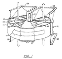
- Figure 1 is a general perspective view of a conventional rotary regenerative air preheater.
- Figure 2 is a perspective view of a portion of a heat transfer element assembly incorporating the present invention.
- Figure 3 is a side view of a portion of a heat transfer element assembly illustrating the flow channels.
- Figure 4 is an enlarged perspective view of a portion of one heat transfer plate illustrating the present invention.
- Figure 5 is a section view of a portion of a plate forming method illustrating the formation of plates with the notches.
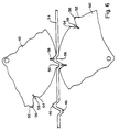
- Figure 6 is a view of another section of the rolls of Figure 5 showing the means for forming the flow disrupting indentations.
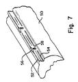
- Figure 7 is a perspective view of a portion of one of the rolls of Figures 5 and 6.
- Figure 8 is a section view of a portion of an alternate plate forming method of the present invention.
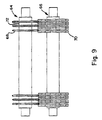
- Figure 9 is a front view of the indentation forming rollers of Figure 8.
- Figure 10 is a perspective view of a portion of a heat transfer element assembly of the present invention applied to undulating plates.
- FIG. 1 of the drawings is a partially cut-away perspective view of a typical air heater showing a housing 12 in which the rotor 14 is mounted on drive shaft or post 16 for rotation as indicated by the arrow 18.
- the rotor is composed of a plurality of sectors 20 with each sector containing a number of basket modules 22 and with each sector being defined by the diaphragms 34.
- the basket modules contain the heat exchange surface.
- the housing is divided by means of the flow impervious sector plate 24 into a flue gas side and an air side. A corresponding sector plate is also located on the bottom of the unit.
- the hot flue gases enter the air heater through the gas inlet duct 26, flow through the rotor where heat is transferred to the rotor and then exit through gas outlet duct 28.
- the countercurrent flowing air enters through air inlet duct 30, flows through the rotor where it picks up heat and then exits through air outlet duct 32.
- FIG. 2 depicts portions of three of the stacked heat exchange plates 34 which are contained in the basket modules 22 and which are formed in accordance with the present invention. Of course, there would be a large number of such plates 34 in each module.
- the plates 34 are stacked in spaced relationship thereby providing passageways 36 and 38 therebetween for the flow of flue gas and air.
- the plates 34 are usually formed of thin sheet metal and are capable of being rolled or stamped to the desired configuration.
- the plates are formed with flat sections 40 and opposed notches 42 which provide the means for spacing the adjacent plates a predetermined distance apart to form the previously mentioned flow channels or passageways 36 and 38,
- Figure 3 which shows a side view of a portion of three stacked plates
- the available area 44 for the flow of fluid between the notches 42 and the adjacent plate which is shown as being cross-hatched is significantly greater per surface area of exposed heat transfer surface than the remaining (uncross-hatched) area for the flow of fluid between the flat sections 40 of adjacent plates.
- This flow path 44 has lower flow resistance and less turbulence and mixing. A greater percentage of the flow per heat transfer surface area of exposed element passes through these channels 44 than through the remainder of the flow passageways 38 and also through the flow passages 36. All of these factors result in a lower heat transfer in this area 44.
- the present invention provides means in the flow channels 44 to disrupt the flow thereby minimally increasing flow resistance, creating turbulence and mixing and disrupting the boundary layer.
- the flow disrupting means thereby improves the specific heat transfer performance in the channels 44 and the overall heat transfer performance of the stacked plates. It also serves to push some of the flow out of the notch channel and intermixes it with the flow in the other areas, for example, flow passages 36 and 38 in Figures 2 and 3. This intermixing reduces temperature differences between the fluid in passage 44 and passages 36 and 38, which would otherwise exist.
- Figure 2 shows the flow disrupting means which comprise deformations or indentations 46 which are formed into the peaks of the notches 42 to extend into the channels 44 at spaced intervals.
- indentations are also shown in Figure 4 which is an enlarged view of a portion of one plate 34 showing these indentations more clearly.
- the dent 46 in the upwardly extending, left hand notch 42 comprises a small depression in the peak of the notch such that the underside of the indentation 46 extends down into flow area 44 under the plate.
- the downwardly extending, right hand notch 42 has an indentation 46 which is similarly formed and which extends up into the right hand flow area 44 on top of the plate.
- Figures 5, 6 and 7 illustrate the equipment used in one method of forming the heat transfer plates of the present invention.
- the opposed forming rolls 48 and 50 which are used to form the notches 42 in the plate 34 are modified to form the indentations 46.
- Figure 5 is a cross section through the rolls and through the plate at a location where there are no indentations.
- the projections 52 on the forming rolls cooperate with the depressions 54 to form the notches 42.
- Figure 6 which is a figure similar to Figure 5, is a cross-section through the rolls and through the plate at a location here the means for forming the indentation are located.
- Figure 7 is a perspective view of a portion of one roil which also illustrates these indentation forming means. As shown, the projections 52 on the forming rolls are cut away at 56 in the shape and to the extent required to form the indentations 46.
- the depressions 54 are fitted with denting pins 58 which project upwardly from the bottom of the depressions 54 and which cooperate with the mating cut away portions 56 on the matching roll to form the indentations.
- Figures 8 and 9 illustrate another method of forming the indentations 46 in the heat transfer plates of the present invention.
- the forming rolls 60 and 62 are similar to the forming rolls 48 and 50 of Figure 5 but they are only for the purpose of forming the notches 42. They are not modified to form the indentations 46.
- the plate 34 with the formed notches 42 is passed through the indentation forming rollers 64 and 66.
- the roller 64 comprises a series of disks 68 which are spaced apart a distance equal to the desired spacing between indentations as shown in Figure 9.
- the roller 64 preferably has spacers 72 between the disks 68 such that the spacers 72 of varying widths can be used to vary the distance between dents.
- the circumferential edges of the disks 68 are shaped and aligned such that they will engage the notches 42 and form indentations of the desired shape and depth.
- the roller 66 is for the purpose of supporting the notches on the sides of the indentations as they are being formed, This provides control of the depth of the indentations and prevents unwanted deformation of the sheet except in the specific area of the indentations.
- the roller 66 comprises a series of disks 70 which contain the notch supports 74, These notch supports are shaped such that they extend into the notches and conform to the shape of the notches. They are aligned on the roller 66 so that there is a support disk 70 on each side of each disk 68 as shown in Figure 9.
- the illustrated support disk 70 is behind the indentation 46 which is being formed. In this particular method. the indentations are formed only on the notches on one side of the plate 34 at a time.
- the invention also applies to other configurations of notched plates.
- the notches may be oriented parallel to the fluid flow or they may be at an angle up to 45°.
- the invention also applies to plates with notches extending out on only one side as opposed to the illustrated double-sided notch arrangement.
- the so-called flat sections of the plates between notches may in fact be an undulated surface as is common in the art. This embodiment is illustrated in Figure 10 where the sections 40 between the notches 42 have undulations or corrugations 76 which are relatively shallow compared to the height of the notches and which are typically inclined at an acute angle to the direction of the notches and the direction of fluid flow.
- the notching rolls can be formed so that they work in conjunction with the undulations to simultaneously form the notches and indentations.
- the notching roll has a discontinuous notch pattern across the width of the roll. In areas where the notch pattern is present, the undulation is flattened and the notch is roll-formed. Where there are gaps in the notch pattern on the roll, the existing undulation shape remains to a significant extent thereby producing the desired effect of an indentation or bump into the notch channel. This may be done with the same equipment shown in Figures 5, 6 and 7 but without the necessity of having the denting pins 58,
- a plate with a notch height of 0.965 cm (0.380 inches) may have indentations spaced at 6.35 cm (2.5 inches) and to an average depth of 0.254 cm (0,100 inches).
- the total width of an indentation may be on the order of 0.635 cm (0.25 inches).
Landscapes
- Engineering & Computer Science (AREA)
- Mechanical Engineering (AREA)
- Physics & Mathematics (AREA)
- Thermal Sciences (AREA)
- General Engineering & Computer Science (AREA)
- Heat-Exchange Devices With Radiators And Conduit Assemblies (AREA)
- Air Supply (AREA)
Claims (7)
- Assemblage d'éléments de transfert thermique pour un échangeur de chaleur régénératif rotatif, comprenant une pluralité de plaques de transfert thermique empilées de manière espacée, en fournissant ainsi une pluralité de passages entre les plaques adjacentes pour l'écoulement du fluide d'échange de chaleur entre elles, chacune desdites plaques ayant des crans espacés s'étendant en travers d'elle et faisant saillie vers l'extérieur depuis ladite plaque jusqu'à un pic, lesdits crans espacés supportant des plaques adjacentes dans ladite relation espacée et fournissant ladite pluralité de passages entre des plaques adjacentes, lesdits crans espacés comportant des indentations formées dans lesdits pics à des intervalles sélectionnés, lesdites indentations saillant depuis lesdits pics dans lesdits passages et dans ledit écoulement de fluide d'échange de chaleur.
- Assemblage d'éléments de transfert thermique selon la revendication 1, dans lequel lesdites plaques de transfert thermique contiennent des ondulations entre lesdits crans espacés.
- Assemblage d'éléments de transfert thermique selon la revendication 2, dans lequel lesdites ondulations sont obliques par rapport à la direction desdits crans.
- Assemblage d'éléments de transfert thermique selon la revendication 1, dans lequel lesdits crans espacés dans chacune desdites plaques comprennent des paires de crans adjacents avec l'une desdites paires faisant saillie vers l'extérieur depuis ladite plaque dans une direction et l'autre desdites paires faisant saillie vers l'extérieur depuis ladite plaque dans la direction opposée.
- Méthode de formation de plaques de transfert thermique pour un échangeur de chaleur, comprenant les étapes consistant à :a. faire passer une tôle de matériau de plaque de transfert thermique à travers une paire de rouleaux de formation ayant des saillies et des retraits de formation de crans, des crans espacés étant ainsi formés dans ledit matériau, s'étendant en travers de celui-ci et faisant saillie vers l'extérieur depuis ledit matériau jusqu'à un pic ; etb. faire passer ledit matériau avec lesdits crans espacés à travers une paire de rouleaux de formation d'indentations, l'une desdites paires de rouleaux de formation d'indentations formant des indentations dans lesdits pics desdits crans à intervalles sélectionnés, et l'autre desdites paires de rouleaux de formation d'indentations supportant lesdits crans adjacents auxdites indentations.
- Méthode de formation de plaques de transfert thermique pour un échangeur de chaleur comprenant les étapes consistant à :a. fournir une tôle de matériau de plaque de transfert thermique ayant des ondulations s'étendant obliquement en travers de celle-ci ;b. fournir une paire coopérante de rouleaux de formation ayant des saillies et des retraits de formation de crans s'étendant en travers desdits rouleaux parallèlement aux axes desdits rouleaux, lesdites saillies de formation de crans ayant des espaces espacés ;c. faire passer ladite tôle de matériau ayant lesdites ondulations à travers ladite paire coopérante de rouleaux de formation, des crans espacés étant ainsi formés dans ledit matériau, s'étendant en travers de celui-ci à un certain angle par rapport auxdites ondulations et saillant vers l'extérieur depuis ledit matériau jusqu'à un -pic plus haut que lesdites ondulations, et lesdits espaces dans lesdites saillies de formation des crans et lesdites ondulations coopérant ainsi pour former des indentations espacées dans lesdits pics desdits crans.
- Méthode de formation de plaques de transfert thermique pour un échangeur de chaleur, comprenant les étapes consistant à :a. fournir une paire coopérante de rouleaux de formation ayant des saillies et des retraits de formation de crans s'étendant en travers desdits rouleaux, lesdites saillies de formation de crans ayant des portions découpées espacées et lesdits retraits ayant des saillies espacées de formation des indentations situées de manière à correspondre et à coopérer avec lesdites portions découpées ;b. faire passer une tôle de matériau de plaque d'échange thermique à travers ladite paire coopérante de rouleaux, des crans espacés étant ainsi formés dans ledit matériau, s'étendant en travers de celui-ci et faisant saillie vers l'extérieur jusqu'à un pic et lesdites portions découpées et lesdites saillies de formation des indentations coopérant ainsi pour former des indentations dans lesdits pics desdits crans.
Applications Claiming Priority (3)
| Application Number | Priority Date | Filing Date | Title |
|---|---|---|---|
| US874291 | 1992-04-24 | ||
| US08/874,291 US5979050A (en) | 1997-06-13 | 1997-06-13 | Air preheater heat transfer elements and method of manufacture |
| PCT/US1998/007023 WO1998057112A1 (fr) | 1997-06-13 | 1998-04-07 | Elements de transfert de chaleur de rechauffeur d'air et procede de fabrication |
Publications (2)
| Publication Number | Publication Date |
|---|---|
| EP0990110A1 EP0990110A1 (fr) | 2000-04-05 |
| EP0990110B1 true EP0990110B1 (fr) | 2001-06-13 |
Family
ID=25363423
Family Applications (1)
| Application Number | Title | Priority Date | Filing Date |
|---|---|---|---|
| EP98915382A Expired - Lifetime EP0990110B1 (fr) | 1997-06-13 | 1998-04-07 | Elements de transfert de chaleur de rechauffeur d'air et procede de fabrication |
Country Status (12)
| Country | Link |
|---|---|
| US (2) | US5979050A (fr) |
| EP (1) | EP0990110B1 (fr) |
| JP (1) | JP3239134B2 (fr) |
| KR (1) | KR100355260B1 (fr) |
| CN (1) | CN1168949C (fr) |
| BR (1) | BR9810254A (fr) |
| CA (1) | CA2292590A1 (fr) |
| DE (1) | DE69800933T2 (fr) |
| ES (1) | ES2159944T3 (fr) |
| ID (1) | ID23682A (fr) |
| PL (1) | PL190740B1 (fr) |
| WO (1) | WO1998057112A1 (fr) |
Families Citing this family (35)
| Publication number | Priority date | Publication date | Assignee | Title |
|---|---|---|---|---|
| DE19652999C2 (de) * | 1996-12-19 | 1999-06-24 | Steag Ag | Wärmespeicherblock für regenerative Wärmetauscher |
| IL124723A (en) * | 1998-06-02 | 2004-01-04 | Pessach Seidel | Method of forming a heat exchanger stack |
| US6205662B1 (en) * | 1999-05-14 | 2001-03-27 | Yun-Ching Chen | Method of producing a built-up heat exchanger and product thereof |
| US6516871B1 (en) * | 1999-08-18 | 2003-02-11 | Alstom (Switzerland) Ltd. | Heat transfer element assembly |
| US6357113B1 (en) * | 1999-11-04 | 2002-03-19 | Williams International Co., L.L.C. | Method of manufacture of a gas turbine engine recuperator |
| US6892795B1 (en) * | 2000-10-04 | 2005-05-17 | Airxchange, Inc. | Embossed regenerator matrix for heat exchanger |
| US6439170B1 (en) * | 2000-12-12 | 2002-08-27 | Alstom Power N.V. | Single seam duct corner |
| US6450245B1 (en) * | 2001-10-24 | 2002-09-17 | Alstom (Switzerland) Ltd. | Air preheater heat transfer elements |
| GB0210434D0 (en) * | 2002-05-08 | 2002-06-12 | Smiths Group Plc | Apparatus |
| AU2003257765A1 (en) * | 2002-07-01 | 2004-01-19 | Nanjing University | A moulding process of composite material including high-thermal--conductor and room-temperature magnetic refrigerant |
| GB2429054A (en) * | 2005-07-29 | 2007-02-14 | Howden Power Ltd | A heating surface element |
| US20070028432A1 (en) * | 2005-08-03 | 2007-02-08 | Alcoa, Inc. | Apparatus and method for separating composite panels into metal skins and polymer cores |
| DE102006003317B4 (de) | 2006-01-23 | 2008-10-02 | Alstom Technology Ltd. | Rohrbündel-Wärmetauscher |
| DE102006062189B4 (de) * | 2006-12-22 | 2009-03-19 | Dr. Mirtsch Gmbh | Verfahren zum Herstellen einer strukturierten Materialbahn für das Durchströmen von fluiden Medien, strukturierte Materialbahn und Verwendung derselben |
| DE102007048474A1 (de) * | 2007-10-09 | 2009-04-16 | Behr Gmbh & Co. Kg | Verfahren zur Herstellung einer Turbulenzvorrichtung, Vorrichtung zur Durchführung des Verfahrens, Turbulenzvorrichtung |
| JP5183342B2 (ja) * | 2008-07-25 | 2013-04-17 | 株式会社Ihi | 固体高分子型燃料電池用セパレータ製造方法及び設備 |
| US9557119B2 (en) | 2009-05-08 | 2017-01-31 | Arvos Inc. | Heat transfer sheet for rotary regenerative heat exchanger |
| US8622115B2 (en) * | 2009-08-19 | 2014-01-07 | Alstom Technology Ltd | Heat transfer element for a rotary regenerative heat exchanger |
| SE535337C2 (sv) | 2010-09-28 | 2012-07-03 | Torgny Lagerstedt Ab | Sätt att höja verkningsgraden i en regenerativ värmeväxlare |
| US20130048261A1 (en) * | 2011-08-26 | 2013-02-28 | Hs Marston Aerospace Ltd. | Heat exhanger |
| CN102374551A (zh) * | 2011-12-12 | 2012-03-14 | 上海锅炉厂有限公司 | 一种空气预热器用传热元件结构 |
| US9200853B2 (en) | 2012-08-23 | 2015-12-01 | Arvos Technology Limited | Heat transfer assembly for rotary regenerative preheater |
| CN104685745B (zh) | 2012-08-27 | 2017-09-08 | 赫尔曼米勒公司 | 分隔系统以及与其一起使用的附件 |
| CN103143937B (zh) * | 2013-03-28 | 2015-04-01 | 上海西重所重型机械成套有限公司 | 一种换热板筐的波纹板对波峰剪切轧制方法 |
| US10175006B2 (en) | 2013-11-25 | 2019-01-08 | Arvos Ljungstrom Llc | Heat transfer elements for a closed channel rotary regenerative air preheater |
| US10094626B2 (en) * | 2015-10-07 | 2018-10-09 | Arvos Ljungstrom Llc | Alternating notch configuration for spacing heat transfer sheets |
| USD799161S1 (en) | 2015-10-09 | 2017-10-10 | Milwaukee Electric Tool Corporation | Garment |
| WO2018125134A1 (fr) * | 2016-12-29 | 2018-07-05 | Arvos, Ljungstrom Llc. | Ensemble feuille de transfert de chaleur à éléments d'espacement intermédiaires |
| US10837714B2 (en) * | 2017-06-29 | 2020-11-17 | Howden Uk Limited | Heat transfer elements for rotary heat exchangers |
| KR101886704B1 (ko) * | 2017-09-25 | 2018-08-08 | 한국남동발전 주식회사 | 가스 재열기의 성능이 향상되는 열소자 |
| PL235069B1 (pl) | 2017-12-04 | 2020-05-18 | Ts Group Spolka Z Ograniczona Odpowiedzialnoscia | Zwój do transmisji ciepła dla obrotowego cylindrycznego wymiennika ciepła |
| US11397059B2 (en) | 2019-09-17 | 2022-07-26 | General Electric Company | Asymmetric flow path topology |
| US12412011B2 (en) * | 2020-01-08 | 2025-09-09 | Control Components, Inc. | Method for three-dimensional tortuous path flow element |
| US11962188B2 (en) | 2021-01-21 | 2024-04-16 | General Electric Company | Electric machine |
| PL246102B1 (pl) * | 2022-02-24 | 2024-12-02 | Andrzej Krupa | Obrotowy metalowy zespół przekazywania ciepła dla obrotowego powietrznego wymiennika ciepła |
Family Cites Families (13)
| Publication number | Priority date | Publication date | Assignee | Title |
|---|---|---|---|---|
| US2329789A (en) * | 1939-11-16 | 1943-09-21 | Mccord Radiator & Mfg Co | Apparatus for making heatexchange elements |
| SE127755C1 (sv) * | 1945-05-28 | 1950-03-28 | Ljungstroms Angturbin Ab | Elementsats för värmeväxlare |
| US2940736A (en) * | 1949-05-25 | 1960-06-14 | Svenska Rotor Maskiner Ab | Element set for heat exchangers |
| GB702137A (en) * | 1949-05-25 | 1954-01-13 | Ljungstroems Aengturbin Ab | Improvements in or relating to plate-type heat exchangers |
| GB899773A (en) * | 1959-05-02 | 1962-06-27 | Archibald Johnstone Engineers | Improvements in or relating to regenerative heat exchangers |
| US4396058A (en) * | 1981-11-23 | 1983-08-02 | The Air Preheater Company | Heat transfer element assembly |
| US4553458A (en) * | 1984-03-28 | 1985-11-19 | The Air Preheater Company, Inc. | Method for manufacturing heat transfer element sheets for a rotary regenerative heat exchanger |
| US4744410A (en) * | 1987-02-24 | 1988-05-17 | The Air Preheater Company, Inc. | Heat transfer element assembly |
| US4930569A (en) * | 1989-10-25 | 1990-06-05 | The Air Preheater Company, Inc. | Heat transfer element assembly |
| DE4122949A1 (de) * | 1991-07-11 | 1993-01-14 | Rothemuehle Brandt Kritzler | Heizblechpaket fuer regenerative waermetauscher sowie verfahren und vorrichtung zur herstellung von profilblechen fuer solche heizblechpakete |
| JP3405997B2 (ja) * | 1991-10-23 | 2003-05-12 | 株式会社デンソー | インナーフィンおよびその製造方法 |
| GB9511847D0 (en) * | 1995-06-10 | 1995-08-09 | Metsec Plc | Metal strip |
| US5836379A (en) * | 1996-11-22 | 1998-11-17 | Abb Air Preheater, Inc. | Air preheater heat transfer surface |
-
1997
- 1997-06-13 US US08/874,291 patent/US5979050A/en not_active Expired - Lifetime
-
1998
- 1998-04-07 CN CNB988060868A patent/CN1168949C/zh not_active Expired - Lifetime
- 1998-04-07 PL PL337339A patent/PL190740B1/pl not_active IP Right Cessation
- 1998-04-07 JP JP50238499A patent/JP3239134B2/ja not_active Expired - Fee Related
- 1998-04-07 ID IDW991409A patent/ID23682A/id unknown
- 1998-04-07 ES ES98915382T patent/ES2159944T3/es not_active Expired - Lifetime
- 1998-04-07 DE DE69800933T patent/DE69800933T2/de not_active Expired - Fee Related
- 1998-04-07 EP EP98915382A patent/EP0990110B1/fr not_active Expired - Lifetime
- 1998-04-07 CA CA002292590A patent/CA2292590A1/fr not_active Abandoned
- 1998-04-07 BR BR9810254-0A patent/BR9810254A/pt not_active Application Discontinuation
- 1998-04-07 KR KR1019997011116A patent/KR100355260B1/ko not_active Expired - Fee Related
- 1998-04-07 WO PCT/US1998/007023 patent/WO1998057112A1/fr not_active Ceased
-
1999
- 1999-05-05 US US09/305,529 patent/US5983985A/en not_active Expired - Lifetime
Also Published As
| Publication number | Publication date |
|---|---|
| CN1260036A (zh) | 2000-07-12 |
| ES2159944T3 (es) | 2001-10-16 |
| ID23682A (id) | 2000-05-11 |
| US5979050A (en) | 1999-11-09 |
| JP2000513090A (ja) | 2000-10-03 |
| EP0990110A1 (fr) | 2000-04-05 |
| CN1168949C (zh) | 2004-09-29 |
| DE69800933D1 (de) | 2001-07-19 |
| JP3239134B2 (ja) | 2001-12-17 |
| CA2292590A1 (fr) | 1998-12-17 |
| BR9810254A (pt) | 2000-09-19 |
| KR100355260B1 (ko) | 2002-10-11 |
| PL337339A1 (en) | 2000-08-14 |
| PL190740B1 (pl) | 2006-01-31 |
| DE69800933T2 (de) | 2001-11-15 |
| KR20010013135A (ko) | 2001-02-26 |
| WO1998057112A1 (fr) | 1998-12-17 |
| US5983985A (en) | 1999-11-16 |
Similar Documents
| Publication | Publication Date | Title |
|---|---|---|
| US5979050A (en) | Air preheater heat transfer elements and method of manufacture | |
| US6019160A (en) | Heat transfer element assembly | |
| JP3531145B2 (ja) | 熱伝達要素組立体 | |
| EP1204837B1 (fr) | Ensemble d'element de transfert de chaleur | |
| JPH01503557A (ja) | 熱伝達要素組立体 | |
| KR20080063271A (ko) | 열 교환면 | |
| GB1566619A (en) | Heat exchange element | |
| EP1015834B1 (fr) | Surface d'echange thermique pour rechauffeur d'air | |
| JPH071155B2 (ja) | 熱伝達要素組立体 | |
| MXPA99010564A (en) | Air preheater heat transfer elements and method of manufacture | |
| US5775405A (en) | Air preheater basket assembly | |
| CZ9904459A3 (cs) | Prvky pro převedení tepla předehřívače vzduchu a způsob jejich výroby | |
| WO2004040221A1 (fr) | Elements de transfert de chaleur de prechauffeur d'air |
Legal Events
| Date | Code | Title | Description |
|---|---|---|---|
| PUAI | Public reference made under article 153(3) epc to a published international application that has entered the european phase |
Free format text: ORIGINAL CODE: 0009012 |
|
| 17P | Request for examination filed |
Effective date: 19991115 |
|
| AK | Designated contracting states |
Kind code of ref document: A1 Designated state(s): DE ES FR GB IT SE |
|
| GRAG | Despatch of communication of intention to grant |
Free format text: ORIGINAL CODE: EPIDOS AGRA |
|
| 17Q | First examination report despatched |
Effective date: 20000724 |
|
| GRAG | Despatch of communication of intention to grant |
Free format text: ORIGINAL CODE: EPIDOS AGRA |
|
| GRAH | Despatch of communication of intention to grant a patent |
Free format text: ORIGINAL CODE: EPIDOS IGRA |
|
| GRAH | Despatch of communication of intention to grant a patent |
Free format text: ORIGINAL CODE: EPIDOS IGRA |
|
| GRAA | (expected) grant |
Free format text: ORIGINAL CODE: 0009210 |
|
| RAP1 | Party data changed (applicant data changed or rights of an application transferred) |
Owner name: ALSTOM POWER INC. |
|
| AK | Designated contracting states |
Kind code of ref document: B1 Designated state(s): DE ES FR GB IT SE |
|
| REF | Corresponds to: |
Ref document number: 69800933 Country of ref document: DE Date of ref document: 20010719 |
|
| ITF | It: translation for a ep patent filed | ||
| ET | Fr: translation filed | ||
| REG | Reference to a national code |
Ref country code: ES Ref legal event code: FG2A Ref document number: 2159944 Country of ref document: ES Kind code of ref document: T3 |
|
| REG | Reference to a national code |
Ref country code: GB Ref legal event code: IF02 |
|
| PGFP | Annual fee paid to national office [announced via postgrant information from national office to epo] |
Ref country code: FR Payment date: 20020328 Year of fee payment: 5 |
|
| PGFP | Annual fee paid to national office [announced via postgrant information from national office to epo] |
Ref country code: SE Payment date: 20020402 Year of fee payment: 5 |
|
| PLBE | No opposition filed within time limit |
Free format text: ORIGINAL CODE: 0009261 |
|
| STAA | Information on the status of an ep patent application or granted ep patent |
Free format text: STATUS: NO OPPOSITION FILED WITHIN TIME LIMIT |
|
| 26N | No opposition filed | ||
| PG25 | Lapsed in a contracting state [announced via postgrant information from national office to epo] |
Ref country code: SE Free format text: LAPSE BECAUSE OF NON-PAYMENT OF DUE FEES Effective date: 20030408 |
|
| EUG | Se: european patent has lapsed | ||
| PG25 | Lapsed in a contracting state [announced via postgrant information from national office to epo] |
Ref country code: FR Free format text: LAPSE BECAUSE OF NON-PAYMENT OF DUE FEES Effective date: 20031231 |
|
| REG | Reference to a national code |
Ref country code: FR Ref legal event code: ST |
|
| PGFP | Annual fee paid to national office [announced via postgrant information from national office to epo] |
Ref country code: DE Payment date: 20040319 Year of fee payment: 7 |
|
| PGFP | Annual fee paid to national office [announced via postgrant information from national office to epo] |
Ref country code: GB Payment date: 20040324 Year of fee payment: 7 |
|
| PGFP | Annual fee paid to national office [announced via postgrant information from national office to epo] |
Ref country code: ES Payment date: 20040414 Year of fee payment: 7 |
|
| PG25 | Lapsed in a contracting state [announced via postgrant information from national office to epo] |
Ref country code: IT Free format text: LAPSE BECAUSE OF NON-PAYMENT OF DUE FEES Effective date: 20050407 Ref country code: GB Free format text: LAPSE BECAUSE OF NON-PAYMENT OF DUE FEES Effective date: 20050407 |
|
| PG25 | Lapsed in a contracting state [announced via postgrant information from national office to epo] |
Ref country code: ES Free format text: LAPSE BECAUSE OF NON-PAYMENT OF DUE FEES Effective date: 20050408 |
|
| PG25 | Lapsed in a contracting state [announced via postgrant information from national office to epo] |
Ref country code: DE Free format text: LAPSE BECAUSE OF NON-PAYMENT OF DUE FEES Effective date: 20051101 |
|
| GBPC | Gb: european patent ceased through non-payment of renewal fee |
Effective date: 20050407 |
|
| REG | Reference to a national code |
Ref country code: ES Ref legal event code: FD2A Effective date: 20050408 |