EP0990182B1 - Guide d'ondes optique monomode a grande surface utile - Google Patents
Guide d'ondes optique monomode a grande surface utile Download PDFInfo
- Publication number
- EP0990182B1 EP0990182B1 EP97927589A EP97927589A EP0990182B1 EP 0990182 B1 EP0990182 B1 EP 0990182B1 EP 97927589 A EP97927589 A EP 97927589A EP 97927589 A EP97927589 A EP 97927589A EP 0990182 B1 EP0990182 B1 EP 0990182B1
- Authority
- EP
- European Patent Office
- Prior art keywords
- refractive index
- profile
- segments
- core
- microns
- Prior art date
- Legal status (The legal status is an assumption and is not a legal conclusion. Google has not performed a legal analysis and makes no representation as to the accuracy of the status listed.)
- Expired - Lifetime
Links
- 230000003287 optical effect Effects 0.000 title claims description 14
- 239000000835 fiber Substances 0.000 claims description 43
- 239000006185 dispersion Substances 0.000 claims description 39
- 239000011521 glass Substances 0.000 claims description 5
- 230000003247 decreasing effect Effects 0.000 claims description 2
- 238000013461 design Methods 0.000 description 25
- 230000009021 linear effect Effects 0.000 description 9
- 238000009792 diffusion process Methods 0.000 description 7
- 239000002019 doping agent Substances 0.000 description 5
- 230000009022 nonlinear effect Effects 0.000 description 5
- 238000012360 testing method Methods 0.000 description 5
- 238000005452 bending Methods 0.000 description 4
- 238000004519 manufacturing process Methods 0.000 description 4
- 238000000034 method Methods 0.000 description 4
- 230000015556 catabolic process Effects 0.000 description 3
- 230000000052 comparative effect Effects 0.000 description 3
- 238000006731 degradation reaction Methods 0.000 description 3
- 238000005094 computer simulation Methods 0.000 description 2
- 238000009826 distribution Methods 0.000 description 2
- 230000000694 effects Effects 0.000 description 2
- 230000005684 electric field Effects 0.000 description 2
- 230000000737 periodic effect Effects 0.000 description 2
- 229910052691 Erbium Inorganic materials 0.000 description 1
- 230000004075 alteration Effects 0.000 description 1
- 238000013459 approach Methods 0.000 description 1
- 230000005540 biological transmission Effects 0.000 description 1
- 238000005253 cladding Methods 0.000 description 1
- 238000004891 communication Methods 0.000 description 1
- 238000005516 engineering process Methods 0.000 description 1
- UYAHIZSMUZPPFV-UHFFFAOYSA-N erbium Chemical compound [Er] UYAHIZSMUZPPFV-UHFFFAOYSA-N 0.000 description 1
- 230000010354 integration Effects 0.000 description 1
- 238000005259 measurement Methods 0.000 description 1
- 230000000644 propagated effect Effects 0.000 description 1
- 230000035945 sensitivity Effects 0.000 description 1
- 238000012956 testing procedure Methods 0.000 description 1
- 238000004804 winding Methods 0.000 description 1
Images




Classifications
-
- G—PHYSICS
- G02—OPTICS
- G02B—OPTICAL ELEMENTS, SYSTEMS OR APPARATUS
- G02B6/00—Light guides; Structural details of arrangements comprising light guides and other optical elements, e.g. couplings
- G02B6/02—Optical fibres with cladding with or without a coating
- G02B6/036—Optical fibres with cladding with or without a coating core or cladding comprising multiple layers
- G02B6/03616—Optical fibres characterised both by the number of different refractive index layers around the central core segment, i.e. around the innermost high index core layer, and their relative refractive index difference
- G02B6/03661—Optical fibres characterised both by the number of different refractive index layers around the central core segment, i.e. around the innermost high index core layer, and their relative refractive index difference having 4 layers only
- G02B6/03666—Optical fibres characterised both by the number of different refractive index layers around the central core segment, i.e. around the innermost high index core layer, and their relative refractive index difference having 4 layers only arranged - + - +
-
- G—PHYSICS
- G02—OPTICS
- G02B—OPTICAL ELEMENTS, SYSTEMS OR APPARATUS
- G02B6/00—Light guides; Structural details of arrangements comprising light guides and other optical elements, e.g. couplings
- G02B6/02—Optical fibres with cladding with or without a coating
- G02B6/02004—Optical fibres with cladding with or without a coating characterised by the core effective area or mode field radius
- G02B6/02009—Large effective area or mode field radius, e.g. to reduce nonlinear effects in single mode fibres
- G02B6/02014—Effective area greater than 60 square microns in the C band, i.e. 1530-1565 nm
-
- G—PHYSICS
- G02—OPTICS
- G02B—OPTICAL ELEMENTS, SYSTEMS OR APPARATUS
- G02B6/00—Light guides; Structural details of arrangements comprising light guides and other optical elements, e.g. couplings
- G02B6/02—Optical fibres with cladding with or without a coating
- G02B6/02214—Optical fibres with cladding with or without a coating tailored to obtain the desired dispersion, e.g. dispersion shifted, dispersion flattened
- G02B6/02219—Characterised by the wavelength dispersion properties in the silica low loss window around 1550 nm, i.e. S, C, L and U bands from 1460-1675 nm
- G02B6/02228—Dispersion flattened fibres, i.e. having a low dispersion variation over an extended wavelength range
- G02B6/02238—Low dispersion slope fibres
- G02B6/02242—Low dispersion slope fibres having a dispersion slope <0.06 ps/km/nm2
-
- G—PHYSICS
- G02—OPTICS
- G02B—OPTICAL ELEMENTS, SYSTEMS OR APPARATUS
- G02B6/00—Light guides; Structural details of arrangements comprising light guides and other optical elements, e.g. couplings
- G02B6/02—Optical fibres with cladding with or without a coating
- G02B6/028—Optical fibres with cladding with or without a coating with core or cladding having graded refractive index
- G02B6/0286—Combination of graded index in the central core segment and a graded index layer external to the central core segment
-
- G—PHYSICS
- G02—OPTICS
- G02B—OPTICAL ELEMENTS, SYSTEMS OR APPARATUS
- G02B6/00—Light guides; Structural details of arrangements comprising light guides and other optical elements, e.g. couplings
- G02B6/02—Optical fibres with cladding with or without a coating
- G02B6/036—Optical fibres with cladding with or without a coating core or cladding comprising multiple layers
- G02B6/03605—Highest refractive index not on central axis
- G02B6/03611—Highest index adjacent to central axis region, e.g. annular core, coaxial ring, centreline depression affecting waveguiding
-
- G—PHYSICS
- G02—OPTICS
- G02B—OPTICAL ELEMENTS, SYSTEMS OR APPARATUS
- G02B6/00—Light guides; Structural details of arrangements comprising light guides and other optical elements, e.g. couplings
- G02B6/02—Optical fibres with cladding with or without a coating
- G02B6/036—Optical fibres with cladding with or without a coating core or cladding comprising multiple layers
- G02B6/03616—Optical fibres characterised both by the number of different refractive index layers around the central core segment, i.e. around the innermost high index core layer, and their relative refractive index difference
- G02B6/03622—Optical fibres characterised both by the number of different refractive index layers around the central core segment, i.e. around the innermost high index core layer, and their relative refractive index difference having 2 layers only
- G02B6/03627—Optical fibres characterised both by the number of different refractive index layers around the central core segment, i.e. around the innermost high index core layer, and their relative refractive index difference having 2 layers only arranged - +
Definitions
- the invention is directed to a single mode optical waveguide fiber designed for use in long distance, high bit rate systems operating in a wavelength range of about 1500 nm to 1600 nm.
- the novel waveguide fiber has a large effective area, over the operating wavelength range, to reduce the non-linear optical effects which distort the telecommunication signal.
- a single mode waveguide having a large effective area, will have reduced non-linear optical effects, including self phase modulation, four wave mixing, cross phase modulation, and non-linear scattering processes. Each of these effects causes degradation of signal in high power systems.
- optical waveguides which:
- An additional requirement, specifically directed to reducing four wave mixing, may be to place the zero dispersion wavelength of the waveguide fiber outside the operating window.
- the model which predicts properties for segmented core designs, was used to generate a family of core designs having an A eff , and a mode power distribution (or electric field intensity distribution) which characterizes waveguide fiber suitable for use in the very highest performance telecommunications systems.
- the particular feature of the novel family of profile designs of this application is that large effective area is combined with a total dispersion slope near zero over a selected operating wavelength range. This combination provides reduced non-linear signal degradation, because of the increased effective area, as well as, reduced linear dispersion over the selected wavelength range.
- the subject invention meets the need for a single mode optical waveguide fiber which offers the benefits of a relatively large effective area together with a substantially flat dispersion slope, i.e., a dispersion slope having a magnitude of about 0.03 ps/nm 2 -km or less, over an extended operating wavelength range.
- the invention provides a single mode waveguide having a glass core comprising at least four segments. Each segment is characterized by a refractive index profile, an outside radius, r i , and a ⁇ i %. The subscript on r and ⁇ refers to a particular segment. The segments are numbered 1 through n beginning with the innermost segment which includes the waveguide long axis centerline. A clad fayer having a refractive index of n c surrounds the core. The core has two non-adjacent segments each having a positive ⁇ %, and two additional non-adjacent segments having negative ⁇ %.
- ⁇ i % and r i have been found which provide for a substantially flat total dispersion curve, i.e., a curve having a slope of about 0.03 ps/nm 2 -km or less, over a pre-selected wavelength range, and, an effective area of at least 60 microns 2 .
- the effective area of several core designs, having this core configuration, are greater than 70 microns 2 .
- a preferred embodiment of the invention provides substantially zero dispersion slope over the wavelength range of about 1450 nm to 1580 nm. This range includes the low attenuation region around 1550 nm and the high gain wavelength range of the erbium optical amplifier.
- the preferred refractive index profile of the positive ⁇ % segments is chosen from the group consisting of alpha profiles, having alpha in the range .of about 1 to 6, step index, rounded step index profiles, and trapezoidal profiles.
- the preferred refractive index profile of the negative ⁇ % segments is chosen from the group consisting of inverted trapezoidal, inverted step, and inverted rounded step index profiles. It is understood that in a particular profile, one negative ⁇ % segment may have an inverted trapezoidal shape while the other negative ⁇ % segment has an inverted rounded step index shape.
- the number of combinations and permutations of the at least four segments refractive index profiles is quite large. Thus, for practical purposes, the search for core index profile designs which provide the required waveguide fiber properties is done using a computer model.
- Dopant diffusion on centerline can cause a central index depression in the shape of an inverted cone. Also, diffusion at the location of abrupt changes in dopant concentration can produce rounding of the shoulders of a step index profile.
- the model is designed to take into account essentially any refractive index profile variation caused by dopant out-diffusion.
- a typical center diffusion depression is an inverted cone having a base radius dimension no greater than about 2 microns.
- Segments 1 and 3 have a positive ⁇ % and segments 2 and 4 have a negative ⁇ %. As noted above, the segments are numbered sequentially beginning at 1 for the segment which includes the long axis of symmetry of the waveguide.
- the radii have limits, r 1 in the range of about 3 to 5 microns, r 2 no greater than about 10 microns, r 3 no greater than about 17 microns, and r 4 no greater than about 25 microns.
- the respective ⁇ % of the segments in this embodiment have limits, ⁇ 1 % in the range of about 0.20% to 0.70%, ⁇ 2 % and ⁇ 4 % in the range of about -0.80% to -0.15%, and, ⁇ 3 % in the range of about 0.05% to 0.20%.
- the core design model may be used in two ways:
- the waveguides are relatively insensitive to variations in the ⁇ i % of +/-3% and variations in the combined radius of +/-1%, as shown by the calculated parameters of Table 1.
- Waveguide designs which also are relatively easy to manufacture and which permit management of dispersion are favored, because of their low cost and added flexibility.
- the designs described herein are well suited to a dispersion managing strategy in which the waveguide dispersion is varied along a waveguide fiber length to toggle the total dispersion between positive and negative values.
- FIGS. 1a and 1b show ⁇ % charted vs. waveguide radius.
- FIGS. 1a and 1b show only four discrete segments, it is understood that the functional requirements may be met by forming a core having more than four segments. However, embodiments having fewer segments are usually easier to manufacture and are therefore preferred.
- Index profile structure characteristic of the novel waveguide fiber is shown by core segments 4 and 8 , which are non-adjacent segments having positive ⁇ %, and, core segments 2 and 6 , which are non-adjacent segments having negative ⁇ %.
- the segments having positive and the negative ⁇ % may be separated by more than one segment.
- the refractive index profile associated with each segment may be adjusted to reach a core design which provides the required waveguide fiber properties.
- Dashed lines 10, 12 , and 14 show alternative refractive index profile shapes for three of the segments comprising the novel waveguide core. Outside radii 5, 7, 9 , and 11 , of the segments also may be varied to arrive at a core design which provides the required waveguide properties. Given the variables; number of segments, segment profile shape, segment ⁇ %, and radius, it is clear that the design problem is most easily addressed using a computer model. The basic elements of such a model are discussed in U.S. 5,483,612.
- FIG. 1b illustrates a variation of the novel waveguide fiber core design in accordance with the present invention.
- the segments having positive ⁇ %, 16 and 20 are the first and third segments.
- the second and fourth segments, 18 and 22 have a negative ⁇ %.
- Lines 3 and 21 in the respective FIGS. 1a and 1b , represent the refractive index of the cladding which is used to calculate the ⁇ %'s characteristic of the segments.
- the chart of FIG. 2a is an embodiment of the novel waveguide core having the four segments, 26, 28, 30 and 32 .
- Each of the segments has a profile shape which is a rounded step.
- the rounding of the corners of the step profiles as well as the centerline refractive index depression 24 may be due to diffusion of dopant during manufacture of the waveguide fiber. It is possible, but often not necessary to compensate, for example, in the doping step, for such diffusion.
- ⁇ 1 % of segment 26 is near 0.39 %
- ⁇ 2 % of segment 28 is near -0.25 %
- ⁇ 3 % of segment 30 is near 0.12 %
- ⁇ 4 % of segment 32 is near -0.25 %.
- the respective outside radius of each of the segments, beginning at the innermost segment and proceeding outward, is about 4 microns, about 6.5 microns, about 15 microns, and about 22 microns.
- This core structure provides a waveguide fiber having the properties:
- the chart of FIG. 2b is an embodiment of the novel waveguide core having the four segments, 36, 38, 40 and 42 .
- Each of the segments has a profile shape which is a rounded step.
- the rounding of the corners of the step profiles as well as the centerline refractive index depression may be due to diffusion of dopant.
- ⁇ 1 % of segment 36 is near 0.40 %
- ⁇ 2 % of segment 38 is near -0.25 %
- ⁇ 3 % of segment 40 is near 0.12 %
- ⁇ 4 % of segment 42 is near -0.25 %.
- the respective outside radius of each of the segments, beginning at the innermost segment and proceeding outward, is about 4 microns, about 6.5 microns, about 15 microns, and about 23.5 microns.
- This core structure provides a waveguide fiber having the properties:
- Cut off wavelength is increased only slightly, but bend resistance is dramatically improved and A eff is increased by about 6 % in the comparative example.
- the structure alterations which combine to produce a waveguide having improved performance are the increase in ⁇ % in the negative index segments and the increase in overall radius. It is an indication of the robustness of the novel core index profile design that an increase in A eff and in bend resistance can be achieved simultaneously.
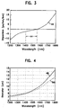
- the total dispersion curve, 46 characteristic of the novel core refractive index profile design is shown in FIG. 3 .
- the flattened region of the curve, 44 spans a wavelength range from about 1400 nm to 1570 nm.
- non-linear dispersion effects are limited due to the larger effective area.
- linear dispersion is limited by maintaining low total dispersion magnitude over the operating wavelength.
- the effective diameter, 48 is larger than the mode field diameter, 50 , over a wavelength range of at least 1200 nm to 1800 nm.
- the larger D eff serves to limit non-linear effects by decreasing signal power per unit area.
- the smaller mode field diameter provides for better bend resistance because a larger fraction of the signal power is guided rather than radiated. It is this feature of the novel waveguide fiber core which limits non-linear effects and at the same time provides good power confinement within the waveguide and thus good bend resistance.
- Curve 54 is the reference curve for a core having a combined radius r.
- Curve 58 is the total dispersion curve for a waveguide fiber having a core combined radius, as defined above, 1 % greater than r.
- Curve 56 is the total dispersion curve for a core combined radius 1 % less than r. Note that the offset of curves 56 and 58 form reference curve 54 does not exceed about 2 ps/nm-km.
- Curve 60 is the reference curve.
- Curves 64 and 62 are represent total dispersion for cases in which the refractive index varies by 3 % and -3 %, respectively.
- curves 64 and 62 do not differ from reference curve 60 by more than about 2 ps/nm-km.
- Table 1 gives the mean and standard deviation of selected waveguide fiber parameters when combined radius is varied by +/-1 % and refractive index is simultaneously varied by +/-3 %.
- the reference profile is substantially that given in comparative example 2.
- the deviation from target values is seen to be small, which indicates the core design provides relatively stable waveguide fiber properties for the stated variations in waveguide fiber core structure.
- the radius variations which produce a change in sign of total dispersion are shown in FIG. 5c with reference to FIG. 5a .
- the reference total dispersion curve 54 A change in combined radius of 1.5 % gives total dispersion curve 68 .
- Combined radius changes of 2.5 % and 4.5 % give total dispersion curves 66 and 70 , respectively.
- the novel core design is readily adaptable to manufacture of dispersion managed waveguide fiber. Periodic changes in radius along the fiber length will produce periodic changes in the sign of the total dispersion so that total dispersion for the entire waveguide fiber length may be essentially zero while the total dispersion magnitude at points along the waveguide fiber are non-zero. This management of total dispersion essentially eliminates four wave mixing while maintaining a very low full fiber length total dispersion.
Landscapes
- Physics & Mathematics (AREA)
- General Physics & Mathematics (AREA)
- Optics & Photonics (AREA)
- Chemical & Material Sciences (AREA)
- Dispersion Chemistry (AREA)
- Optical Integrated Circuits (AREA)
- Lasers (AREA)
- Optical Fibers, Optical Fiber Cores, And Optical Fiber Bundles (AREA)
Claims (5)
- Une fibre de guide d'ondes optique monomode comprenant :dans laquelle au moins deux segments de coeur non adjacents ont un pourcentage d'écart d'indice de réfraction Δ% qui est positif, et au moins deux segments de coeur non adjacents ont un pourcentage d'écart d'indice de réfraction Δ% qui est négatif ; etun coeur en verre, disposé symétriquement autour de la ligne centrale de l'axe longitudinal de la fibre de guide d'ondes, et comportant au moins quatre segments, chacun desdits segments possédant un profil d'indice de réfraction, un pourcentage d'écart d'indice de réfraction Δi% et un rayon extérieur ri, i étant un entier qui désigne un segment particulier, les segments étant numérotés successivement de 1 à n en commençant par 1 sur la ligne centrale ;un couche de gainage en verre formée par-dessus et enfermant ledit coeur, ladite couche de gainage ayant un indice de réfraction nc ;
dans laquelle le rayon extérieur ri et le pourcentage d'écart d'indice de réfraction Δi% de chacun desdits segments sont choisis de manière à fournir une pente de dispersion ayant une grandeur d'environ 0,03 ps/nm2-km ou moins sur un domaine de longueurs d'onde présélectionné,
caractérisée en ce que r1 se situe dans l'intervalle de d'environ 3 à 5 microns, r2 est non supérieur à environ 10 microns, r3 est non supérieur à environ 17 microns, r4 est non supérieur à environ 25 microns, et r4 > r3 > r2 > r1, et
Δi% se situe dans l'intervalle d'environ 0,20 % à 0,70 %, Δ2% se situe dans l'intervalle d'environ -0,80 % à -0,15 %, Δ3% se situe dans l'intervalle d'environ 0,05 % à 0,20 % et Δ4% se situe dans l'intervalle d'environ -0,80 % à -0,15 %,
la section efficace étant supérieure à 60 microns2. - La fibre de guide d'ondes optique monomode de la revendication 1, dans laquelle les premier et troisième segments ont un profil d'indice de réfraction choisi dans le groupe formé par les profils en alpha dans lesquels alpha vaut de 1 à environ 6, les profils d'indice en créneau, les profits d'indice en créneau arrondi et les profils trapézoïdaux, et dans laquelle les deuxième et quatrième segments ont un profil d'indice de réfraction choisi dans le groupe formé par les profils d'indice en créneau renversé, les profils d'indice en créneau arrondi renversé et les profils d'indice trapézoïdaux renversés.
- La fibre de guide d'ondes optique monomode de la revendication 2, dans laquelle le profil d'indice de réfraction du premier segment dudit coeur en verre présente un indice de réfraction maximum n1, à distance de la ligne centrale du guide d'ondes, le profil d'indice de réfraction étant à décroissance monotone entre n1 et la ligne centrale, pour former autour de la ligne centrale une dépression d'indice sensiblement en forme de cône renversé, le cône renversé ayant un rayon de base non supérieur à environ 2 microns.
- La fibre de guide d'ondes optique monomode de la revendication 1, dans laquelle les propriétés fonctionnelles sont relativement insensibles à une variation de Δi% de ± 3 % et à une variation de rayon combiné de ± 1 %.
- La fibre monomode de la revendication 1, dans laquelle le profil de coeur est ajusté le long de la fibre de façon à assurer le réglage de la dispersion totale, associée à une longueur de fibre, à une valeur présélectionnée.
Applications Claiming Priority (5)
| Application Number | Priority Date | Filing Date | Title |
|---|---|---|---|
| US1212496P | 1996-02-23 | 1996-02-23 | |
| US12124P | 1996-02-23 | ||
| US770402 | 1996-12-20 | ||
| US08/770,402 US5684909A (en) | 1996-02-23 | 1996-12-20 | Large effective area single mode optical waveguide |
| PCT/US1997/002543 WO1997033188A2 (fr) | 1996-02-23 | 1997-02-19 | Guide d'ondes optique monomode a grande surface utile |
Publications (3)
| Publication Number | Publication Date |
|---|---|
| EP0990182A4 EP0990182A4 (fr) | 2000-04-05 |
| EP0990182A2 EP0990182A2 (fr) | 2000-04-05 |
| EP0990182B1 true EP0990182B1 (fr) | 2004-01-28 |
Family
ID=26683189
Family Applications (1)
| Application Number | Title | Priority Date | Filing Date |
|---|---|---|---|
| EP97927589A Expired - Lifetime EP0990182B1 (fr) | 1996-02-23 | 1997-02-19 | Guide d'ondes optique monomode a grande surface utile |
Country Status (9)
| Country | Link |
|---|---|
| US (1) | US5684909A (fr) |
| EP (1) | EP0990182B1 (fr) |
| JP (1) | JP3219200B2 (fr) |
| KR (1) | KR100438193B1 (fr) |
| CN (1) | CN1105929C (fr) |
| AU (1) | AU706828B2 (fr) |
| CA (1) | CA2246445A1 (fr) |
| DE (1) | DE69727400D1 (fr) |
| WO (1) | WO1997033188A2 (fr) |
Families Citing this family (74)
| Publication number | Priority date | Publication date | Assignee | Title |
|---|---|---|---|---|
| US5822488A (en) * | 1995-10-04 | 1998-10-13 | Sumitomo Electric Industries, Inc. | Single-mode optical fiber with plural core portions |
| US5781684A (en) * | 1996-12-20 | 1998-07-14 | Corning Incorporated | Single mode optical waveguide having large effective area |
| CA2225889A1 (fr) * | 1996-12-27 | 1998-06-27 | Sumitomo Electric Industries, Ltd. | Fibre a dispersion decalee |
| WO1999008142A1 (fr) * | 1997-08-07 | 1999-02-18 | Corning Incorporated | Fibre de guide d'onde optique a compensation de dispersion |
| JP3830636B2 (ja) * | 1997-10-14 | 2006-10-04 | 株式会社フジクラ | 分散シフト光ファイバ |
| EP1027623A1 (fr) * | 1997-10-29 | 2000-08-16 | Corning Incorporated | Profil de guide d'onde pour aire efficace etendue |
| WO1999022258A1 (fr) * | 1997-10-29 | 1999-05-06 | Sumitomo Electric Industries, Ltd. | Fibre optique a dephasage dispersif |
| US6031956A (en) * | 1997-11-17 | 2000-02-29 | Corning Incorporated | High performance single mode waveguide |
| AU740596B2 (en) | 1997-12-05 | 2001-11-08 | Sumitomo Electric Industries, Ltd. | Dispersion-shifted optical fiber |
| WO1999030193A1 (fr) | 1997-12-05 | 1999-06-17 | Sumitomo Electric Industries, Ltd. | Fibre optique a dispersion plate |
| WO1999032909A1 (fr) * | 1997-12-22 | 1999-07-01 | Sumitomo Electric Industries, Ltd. | Ligne de transmission optique |
| US6421490B1 (en) | 1998-02-23 | 2002-07-16 | Corning Incorporated | Low slope dispersion managed waveguide |
| US6396986B1 (en) | 1998-04-22 | 2002-05-28 | Corning Incorporated | Method of making optical fibers |
| CA2330844A1 (fr) * | 1998-04-30 | 1999-11-11 | Sumitomo Electric Industries, Ltd. | Fibre optique |
| US6321016B1 (en) | 1998-06-19 | 2001-11-20 | Pirelli Cavi E Sistemi S.P.A. | Optical fiber having low non-linearity for WDM transmission |
| BR9912005C1 (pt) * | 1998-07-14 | 2006-06-13 | Corning Inc | guia de onda ótica de modo simples |
| US6343176B1 (en) * | 1998-07-31 | 2002-01-29 | Corning Incorporated | Long haul single mode waveguide |
| FR2782390A1 (fr) * | 1998-08-13 | 2000-02-18 | Alsthom Cge Alcatel | Fibre optique monomode a dispersion decalee et a creux central |
| FR2782391A1 (fr) * | 1998-08-13 | 2000-02-18 | Alsthom Cge Alcatel | Ajout d'un anneau externe au profil d'indice d'une fibre optique monomode a dispersion decalee |
| DE19839870A1 (de) * | 1998-09-02 | 2000-03-09 | Deutsche Telekom Ag | Optische Single-Mode-Lichtleitfaser |
| US6212322B1 (en) * | 1998-09-11 | 2001-04-03 | Corning Incorporated | Positive dispersion low dispersion slope fiber |
| US6535676B1 (en) | 1998-09-17 | 2003-03-18 | Alcatel | Optical fibre with optimized ratio of effective area to dispersion scope for optical fibre transmission system with wavelength multiplexing |
| FR2790107B1 (fr) * | 1999-02-18 | 2001-05-04 | Cit Alcatel | Fibre de ligne pour systemes de transmission a fibre optique a multiplexage en longueurs d'onde |
| FR2783609B1 (fr) | 1998-09-17 | 2002-08-30 | Cit Alcatel | Fibre optique monomode optimisee pour les hauts debits |
| KR100636332B1 (ko) | 1998-09-21 | 2006-10-19 | 피렐리 카비 에 시스테미 소시에떼 퍼 아찌오니 | 확장 파장 밴드용의 광파이버 |
| BR9913979A (pt) * | 1998-09-21 | 2001-06-12 | Pirelli Cavi E Sistemi Spa | Fibra ótica para transmissão de modo único, e, processo para produzir fibra ótica de modo único |
| FR2784197B1 (fr) | 1998-10-05 | 2000-12-15 | Cit Alcatel | Fibre optique monomode a dispersion decalee a grande aire effective |
| CA2352268A1 (fr) | 1998-11-26 | 2000-06-02 | Sumitomo Electric Industries, Ltd. | Fibre optique et systeme de transmission optique renfermant celle-ci |
| CN1231775C (zh) * | 1998-12-18 | 2005-12-14 | 皮雷利·卡维系统有限公司 | 城域或接入光通信系统以及用于该系统的光纤和传输方法 |
| CN1168236C (zh) | 1998-12-18 | 2004-09-22 | 皮雷利·卡维系统有限公司 | 在光传输线上发送信号的方法以及光通信系统 |
| EP1653262A3 (fr) * | 1998-12-18 | 2006-05-10 | Prysmian Cavi e Sistemi Energia S.r.l. | Système et procédé optique ayant une perte faible et des effects non-lineaire minimes |
| AU779898B2 (en) * | 1998-12-18 | 2005-02-17 | Prysmian Cavi E Sistemi Energia S.R.L. | Optical system and method having low loss and non-linear effects |
| FR2788138B1 (fr) * | 1999-01-04 | 2001-03-30 | Cit Alcatel | Fibre optique a faible pente de dispersion chromatique |
| TW451088B (en) | 1999-04-16 | 2001-08-21 | Sumitomo Electric Industries | Optical fiber and optical transmission line including the same |
| BR0010173A (pt) * | 1999-04-30 | 2002-01-15 | Corning Inc | Fibra de compensação de dispersão |
| CN100353192C (zh) * | 1999-07-12 | 2007-12-05 | 株式会社藤仓 | 色散位移光纤 |
| CN1237356C (zh) * | 1999-07-27 | 2006-01-18 | 康宁股份有限公司 | 具有功率限制凹陷的光纤 |
| EP1116972A4 (fr) | 1999-07-27 | 2005-10-19 | Fujikura Ltd | Fibre optique a dispersion decalee |
| US6430346B1 (en) * | 1999-09-03 | 2002-08-06 | Corning Incorporated | Negative dispersion single mode waveguide fiber |
| DE60042109D1 (de) | 1999-09-09 | 2009-06-10 | Fujikura Ltd | Dispersionsverschobene optische faser |
| US6424778B1 (en) | 1999-09-29 | 2002-07-23 | Corning Incorporated | Optical fiber with large effective area and low dispersion slope for submarine applications |
| WO2001038911A1 (fr) * | 1999-11-22 | 2001-05-31 | Corning Incorporated | Fibre guide d'ondes a dispersion decalee a grande surface efficace |
| US6324327B1 (en) * | 1999-11-23 | 2001-11-27 | Corning Incorporated | Low dispersion slope negative dispersion optical fiber |
| EP1111414A3 (fr) | 1999-12-13 | 2007-08-08 | Sumitomo Electric Industries, Ltd. | Fibre optique et système de transmission optique |
| JP2001166173A (ja) | 1999-12-13 | 2001-06-22 | Sumitomo Electric Ind Ltd | 光ファイバ |
| JP4134468B2 (ja) | 1999-12-13 | 2008-08-20 | 住友電気工業株式会社 | 光ファイバ |
| FR2805620B1 (fr) | 2000-02-24 | 2002-05-31 | Cit Alcatel | Fibre optique monomode en cable pour reseau de transmission a fibre optique a multiplexage en longueur d'onde |
| US6640038B2 (en) * | 2000-05-31 | 2003-10-28 | Corning Incorporated | Dispersion managed fibers having reduced sensitivity to manufacturing variabilities |
| US6418258B1 (en) | 2000-06-09 | 2002-07-09 | Gazillion Bits, Inc. | Microstructured optical fiber with improved transmission efficiency and durability |
| EP1182472B1 (fr) * | 2000-08-23 | 2006-04-05 | Matsushita Electric Industrial Co., Ltd. | Elément optique et procédé de sa fabrication |
| JP2002261366A (ja) * | 2000-12-26 | 2002-09-13 | Sumitomo Electric Ind Ltd | 増幅用光ファイバ及びそれを含む光ファイバ増幅器 |
| US6516124B2 (en) * | 2001-03-02 | 2003-02-04 | Optical Power Systems Incorporated | Fiber for enhanced energy absorption |
| EP1246380A3 (fr) * | 2001-03-30 | 2004-01-14 | Sumitomo Electric Industries, Ltd. | Compensateur de dispersion pour fibre optique |
| JP4443788B2 (ja) | 2001-03-30 | 2010-03-31 | 古河電気工業株式会社 | 光ファイバおよびその光ファイバを用いた光通信システム |
| US6599957B2 (en) | 2001-05-07 | 2003-07-29 | Corning Incorporated | Photosensitive material suitable for making waveguides and method of making waveguides utilizing this photosensitive optical material |
| US6744951B2 (en) | 2001-05-07 | 2004-06-01 | Cornigg Incorporated | Waveguides and method of making them |
| JP2003004995A (ja) * | 2001-06-26 | 2003-01-08 | Fujikura Ltd | 分散補償光ファイバ及び分散補償光ファイバモジュール |
| US6789960B2 (en) | 2001-07-06 | 2004-09-14 | Corning Incorporated | Method of connecting optical fibers, an optical fiber therefor, and an optical fiber span therefrom |
| WO2003044577A2 (fr) * | 2001-11-15 | 2003-05-30 | Corning Incorporated | Fibre optique guide d'onde a grande capacite |
| US6801699B1 (en) | 2001-11-15 | 2004-10-05 | Corning Incorporated | High capacity optical waveguide fiber |
| KR20040075982A (ko) | 2002-02-15 | 2004-08-30 | 코닝 인코포레이티드 | 저기울기 분산 편이 광섬유 |
| US6798962B2 (en) * | 2002-02-26 | 2004-09-28 | Corning Incorporated | Broadband access optimized fiber and method of making |
| US20040022509A1 (en) * | 2002-07-31 | 2004-02-05 | Pushkar Tandon | Non-zero dispersion shifted optical fiber with depressed core having large effective area, low slope and low dispersion |
| JP2005534963A (ja) * | 2002-07-31 | 2005-11-17 | コーニング・インコーポレーテッド | 大なる実効面積、低傾斜及び低ゼロ分散である非ゼロ分散シフト光ファイバ |
| US20040076392A1 (en) * | 2002-10-17 | 2004-04-22 | Bickham Scott R. | Low Kappa, dual-moat DC fiber and optical transmission line |
| US20040081414A1 (en) * | 2002-10-28 | 2004-04-29 | Barker Delmar L. | Type of optical/RF transmission fiber constructed from left handed materials (LHM) with air core capable of high power transmission |
| US7103251B2 (en) * | 2002-12-31 | 2006-09-05 | Corning Incorporated | Dispersion flattened NZDSF fiber |
| KR100506311B1 (ko) * | 2003-01-20 | 2005-08-05 | 삼성전자주식회사 | 광대역 분산 제어 광섬유 |
| JP2004328149A (ja) * | 2003-04-22 | 2004-11-18 | Sumitomo Electric Ind Ltd | 光伝送システム |
| JP2005031581A (ja) * | 2003-07-11 | 2005-02-03 | Sumitomo Electric Ind Ltd | 光ファイバ、光ファイバ伝送路及び光伝送システム |
| US7003203B2 (en) * | 2003-07-18 | 2006-02-21 | Corning Incorporated | Large effective area, low kappa, dispersion compensating optical fiber and telecommunication span including same |
| US7171090B2 (en) * | 2005-06-30 | 2007-01-30 | Corning Incorporated | Low attenuation optical fiber |
| CN101373237B (zh) * | 2007-08-22 | 2010-05-26 | 富通集团有限公司 | 一种优化色散特性的单模光纤 |
| US9042692B2 (en) * | 2013-08-27 | 2015-05-26 | Corning Cable Systems Llc | Universal optical fibers for optical fiber connectors |
Family Cites Families (5)
| Publication number | Priority date | Publication date | Assignee | Title |
|---|---|---|---|---|
| US4715679A (en) * | 1981-12-07 | 1987-12-29 | Corning Glass Works | Low dispersion, low-loss single-mode optical waveguide |
| US5363463A (en) * | 1982-08-06 | 1994-11-08 | Kleinerman Marcos Y | Remote sensing of physical variables with fiber optic systems |
| US4852968A (en) * | 1986-08-08 | 1989-08-01 | American Telephone And Telegraph Company, At&T Bell Laboratories | Optical fiber comprising a refractive index trench |
| US4770492A (en) * | 1986-10-28 | 1988-09-13 | Spectran Corporation | Pressure or strain sensitive optical fiber |
| US5553185A (en) * | 1994-12-27 | 1996-09-03 | Corning Incorporated | Controlled dispersion optical waveguide |
-
1996
- 1996-12-20 US US08/770,402 patent/US5684909A/en not_active Expired - Fee Related
-
1997
- 1997-02-19 WO PCT/US1997/002543 patent/WO1997033188A2/fr not_active Ceased
- 1997-02-19 KR KR10-1998-0706431A patent/KR100438193B1/ko not_active Expired - Fee Related
- 1997-02-19 EP EP97927589A patent/EP0990182B1/fr not_active Expired - Lifetime
- 1997-02-19 CA CA002246445A patent/CA2246445A1/fr not_active Abandoned
- 1997-02-19 CN CN97192538A patent/CN1105929C/zh not_active Expired - Fee Related
- 1997-02-19 DE DE69727400T patent/DE69727400D1/de not_active Expired - Lifetime
- 1997-02-19 AU AU32021/97A patent/AU706828B2/en not_active Ceased
- 1997-02-19 JP JP53177997A patent/JP3219200B2/ja not_active Expired - Fee Related
Also Published As
| Publication number | Publication date |
|---|---|
| AU706828B2 (en) | 1999-06-24 |
| CN1212057A (zh) | 1999-03-24 |
| WO1997033188A2 (fr) | 1997-09-12 |
| AU3202197A (en) | 1997-09-22 |
| CN1105929C (zh) | 2003-04-16 |
| DE69727400D1 (de) | 2004-03-04 |
| JPH11506228A (ja) | 1999-06-02 |
| EP0990182A4 (fr) | 2000-04-05 |
| CA2246445A1 (fr) | 1997-09-12 |
| KR19990087046A (ko) | 1999-12-15 |
| JP3219200B2 (ja) | 2001-10-15 |
| EP0990182A2 (fr) | 2000-04-05 |
| US5684909A (en) | 1997-11-04 |
| KR100438193B1 (ko) | 2004-10-06 |
Similar Documents
| Publication | Publication Date | Title |
|---|---|---|
| US5684909A (en) | Large effective area single mode optical waveguide | |
| WO1997033188A9 (fr) | Guide d'ondes optique monomode a grande surface utile | |
| EP0724171B1 (fr) | Fibre optique avec une grande section effective | |
| EP0779524B1 (fr) | Guide d'ondes optiques monomode avec une grande section effective | |
| KR100353755B1 (ko) | 분산플랫 광파이버 | |
| EP0721119B1 (fr) | Guide d'onde optique à dispersion contrôlée | |
| US6317551B1 (en) | Optical waveguide having negative dispersion and large Aeff | |
| KR100728452B1 (ko) | 분산천이파이버 | |
| US6618533B2 (en) | Positive dispersion low dispersion slope fiber | |
| JP3267302B2 (ja) | 分散補正単一モード導波路 | |
| US6421491B1 (en) | Dispersion shifted large effective area waveguide fiber | |
| JP5033290B2 (ja) | 分散勾配補償光導波路ファイバ | |
| EP0789255B1 (fr) | Fibre optique monomode ayant une large surface effective | |
| JP2002525671A (ja) | Wdm光ファイバ伝送システム用の有効面積と分散勾配との最適化された比を有する光ファイバ | |
| US6031956A (en) | High performance single mode waveguide | |
| KR100342711B1 (ko) | 삼중클래드의분산이동광섬유 | |
| US6434310B1 (en) | Single mode optical waveguide fiber with reduced dispersion | |
| US6343176B1 (en) | Long haul single mode waveguide | |
| US6647191B2 (en) | Optical fiber with large effective area, low dispersion and low dispersion slope | |
| US6389208B1 (en) | High dispersion zero waveguide fiber | |
| JP2003522337A (ja) | 長距離通信用シングルモード光導波路 | |
| EP0984305A1 (fr) | Fibre optique monomode à longue distance | |
| KR20010053516A (ko) | 단일모드 광도파관 | |
| RU2172507C2 (ru) | Одномодовый оптический волновод с большой эффективной площадью |
Legal Events
| Date | Code | Title | Description |
|---|---|---|---|
| PUAI | Public reference made under article 153(3) epc to a published international application that has entered the european phase |
Free format text: ORIGINAL CODE: 0009012 |
|
| 17P | Request for examination filed |
Effective date: 19980813 |
|
| A4 | Supplementary search report drawn up and despatched |
Effective date: 19990212 |
|
| AK | Designated contracting states |
Kind code of ref document: A4 Designated state(s): CH DE DK FR GB IT LI Kind code of ref document: A2 Designated state(s): CH DE DK FR GB IT LI |
|
| 17Q | First examination report despatched |
Effective date: 20001120 |
|
| GRAP | Despatch of communication of intention to grant a patent |
Free format text: ORIGINAL CODE: EPIDOSNIGR1 |
|
| GRAS | Grant fee paid |
Free format text: ORIGINAL CODE: EPIDOSNIGR3 |
|
| GRAA | (expected) grant |
Free format text: ORIGINAL CODE: 0009210 |
|
| AK | Designated contracting states |
Kind code of ref document: B1 Designated state(s): CH DE DK FR GB IT LI |
|
| PG25 | Lapsed in a contracting state [announced via postgrant information from national office to epo] |
Ref country code: LI Free format text: LAPSE BECAUSE OF FAILURE TO SUBMIT A TRANSLATION OF THE DESCRIPTION OR TO PAY THE FEE WITHIN THE PRESCRIBED TIME-LIMIT Effective date: 20040128 Ref country code: CH Free format text: LAPSE BECAUSE OF FAILURE TO SUBMIT A TRANSLATION OF THE DESCRIPTION OR TO PAY THE FEE WITHIN THE PRESCRIBED TIME-LIMIT Effective date: 20040128 |
|
| REG | Reference to a national code |
Ref country code: GB Ref legal event code: FG4D |
|
| REG | Reference to a national code |
Ref country code: CH Ref legal event code: EP |
|
| REF | Corresponds to: |
Ref document number: 69727400 Country of ref document: DE Date of ref document: 20040304 Kind code of ref document: P |
|
| PG25 | Lapsed in a contracting state [announced via postgrant information from national office to epo] |
Ref country code: DK Free format text: LAPSE BECAUSE OF FAILURE TO SUBMIT A TRANSLATION OF THE DESCRIPTION OR TO PAY THE FEE WITHIN THE PRESCRIBED TIME-LIMIT Effective date: 20040428 |
|
| PG25 | Lapsed in a contracting state [announced via postgrant information from national office to epo] |
Ref country code: DE Free format text: LAPSE BECAUSE OF FAILURE TO SUBMIT A TRANSLATION OF THE DESCRIPTION OR TO PAY THE FEE WITHIN THE PRESCRIBED TIME-LIMIT Effective date: 20040429 |
|
| REG | Reference to a national code |
Ref country code: CH Ref legal event code: PL |
|
| ET | Fr: translation filed | ||
| PLBE | No opposition filed within time limit |
Free format text: ORIGINAL CODE: 0009261 |
|
| STAA | Information on the status of an ep patent application or granted ep patent |
Free format text: STATUS: NO OPPOSITION FILED WITHIN TIME LIMIT |
|
| 26N | No opposition filed |
Effective date: 20041029 |
|
| PGFP | Annual fee paid to national office [announced via postgrant information from national office to epo] |
Ref country code: GB Payment date: 20050216 Year of fee payment: 9 |
|
| PGFP | Annual fee paid to national office [announced via postgrant information from national office to epo] |
Ref country code: FR Payment date: 20050217 Year of fee payment: 9 |
|
| PG25 | Lapsed in a contracting state [announced via postgrant information from national office to epo] |
Ref country code: GB Free format text: LAPSE BECAUSE OF NON-PAYMENT OF DUE FEES Effective date: 20060219 |
|
| PGFP | Annual fee paid to national office [announced via postgrant information from national office to epo] |
Ref country code: IT Payment date: 20060228 Year of fee payment: 10 |
|
| GBPC | Gb: european patent ceased through non-payment of renewal fee |
Effective date: 20060219 |
|
| REG | Reference to a national code |
Ref country code: FR Ref legal event code: ST Effective date: 20061031 |
|
| PG25 | Lapsed in a contracting state [announced via postgrant information from national office to epo] |
Ref country code: FR Free format text: LAPSE BECAUSE OF NON-PAYMENT OF DUE FEES Effective date: 20060228 |
|
| PG25 | Lapsed in a contracting state [announced via postgrant information from national office to epo] |
Ref country code: IT Free format text: LAPSE BECAUSE OF NON-PAYMENT OF DUE FEES Effective date: 20070219 |