EP0990765B1 - Tube carottier à percussion - Google Patents
Tube carottier à percussion Download PDFInfo
- Publication number
- EP0990765B1 EP0990765B1 EP99400428A EP99400428A EP0990765B1 EP 0990765 B1 EP0990765 B1 EP 0990765B1 EP 99400428 A EP99400428 A EP 99400428A EP 99400428 A EP99400428 A EP 99400428A EP 0990765 B1 EP0990765 B1 EP 0990765B1
- Authority
- EP
- European Patent Office
- Prior art keywords
- core tube
- hammer
- bits
- equipment according
- pressure fluid
- Prior art date
- Legal status (The legal status is an assumption and is not a legal conclusion. Google has not performed a legal analysis and makes no representation as to the accuracy of the status listed.)
- Expired - Lifetime
Links
Images




Classifications
-
- E—FIXED CONSTRUCTIONS
- E21—EARTH OR ROCK DRILLING; MINING
- E21B—EARTH OR ROCK DRILLING; OBTAINING OIL, GAS, WATER, SOLUBLE OR MELTABLE MATERIALS OR A SLURRY OF MINERALS FROM WELLS
- E21B4/00—Drives for drilling, used in the borehole
- E21B4/16—Plural down-hole drives, e.g. for combined percussion and rotary drilling; Drives for multi-bit drilling units
-
- E—FIXED CONSTRUCTIONS
- E21—EARTH OR ROCK DRILLING; MINING
- E21B—EARTH OR ROCK DRILLING; OBTAINING OIL, GAS, WATER, SOLUBLE OR MELTABLE MATERIALS OR A SLURRY OF MINERALS FROM WELLS
- E21B10/00—Drill bits
- E21B10/02—Core bits
-
- E—FIXED CONSTRUCTIONS
- E21—EARTH OR ROCK DRILLING; MINING
- E21B—EARTH OR ROCK DRILLING; OBTAINING OIL, GAS, WATER, SOLUBLE OR MELTABLE MATERIALS OR A SLURRY OF MINERALS FROM WELLS
- E21B21/00—Methods or apparatus for flushing boreholes, e.g. by use of exhaust air from motor
- E21B21/12—Methods or apparatus for flushing boreholes, e.g. by use of exhaust air from motor using drilling pipes with plural fluid passages, e.g. closed circulation systems
-
- E—FIXED CONSTRUCTIONS
- E21—EARTH OR ROCK DRILLING; MINING
- E21B—EARTH OR ROCK DRILLING; OBTAINING OIL, GAS, WATER, SOLUBLE OR MELTABLE MATERIALS OR A SLURRY OF MINERALS FROM WELLS
- E21B21/00—Methods or apparatus for flushing boreholes, e.g. by use of exhaust air from motor
- E21B21/14—Methods or apparatus for flushing boreholes, e.g. by use of exhaust air from motor using liquids and gases, e.g. foams
-
- E—FIXED CONSTRUCTIONS
- E21—EARTH OR ROCK DRILLING; MINING
- E21B—EARTH OR ROCK DRILLING; OBTAINING OIL, GAS, WATER, SOLUBLE OR MELTABLE MATERIALS OR A SLURRY OF MINERALS FROM WELLS
- E21B25/00—Apparatus for obtaining or removing undisturbed cores, e.g. core barrels or core extractors
-
- E—FIXED CONSTRUCTIONS
- E21—EARTH OR ROCK DRILLING; MINING
- E21B—EARTH OR ROCK DRILLING; OBTAINING OIL, GAS, WATER, SOLUBLE OR MELTABLE MATERIALS OR A SLURRY OF MINERALS FROM WELLS
- E21B4/00—Drives for drilling, used in the borehole
- E21B4/06—Down-hole impacting means, e.g. hammers
- E21B4/14—Fluid operated hammers
Definitions
- the present invention relates to an equipment for boring large diameter holes into rocks.
- large diameter holes mean holes having a diameter within the range of 1 to 3 metres and a depth within the range of one to 10 metres into the rock. Such holes are to be bored in the rock for foundation piles or other similar purposes.
- the surface of the rock may be at ground level or may be covered by up to 50 metres or more of soil. Where there is soil lying over the rock, a hole will be bored down to the rock by some other means, and held open by a steel casing or support fluid, or a combination of both. Then a specific equipment is used to drill the rock itself.
- a rock roller bit requires considerable downward force to be applied to the rollers to penetrate into the rock.
- the bit is normally attached to a drill pipe which is rotated by a machine at the ground surface. Vertical force is applied to the bit either by hydraulic rams pressing down on the drill pipe or by heavy collars attached to the drill pipe on top of the bit.
- the rollers are equipped with teeth or hemispherical buttons which crush the rock as they pass over its surface. Discs are also used for this purpose in very strong rock.
- a percussive drill penetrates into the rock at a much faster rate than a rock roller bit or a rock roller core barrel. It is normally operated by compressed air which drives a single large hammer and bit or a number of smaller hammers and bits arranged together in a cluster.
- the drill is normally attached to a drill pipe which is rotated by a machine at the ground surface and is also used to convey the compressed air to the hammer or hammers.
- the energy required to operate a percussive drill is much higher than for a rock roller bit or rock roller core barrel, but is needed over a much shorter period.
- Boring augers, toothed core barrels, digging buckets, cleaning buckets and chisels are used mainly for boring holes in weak rocks where acceptable progress can be made with this type of equipment. These tools, with the exception of the chisel, are normally attached to the Kelly bar of a piling rig. Chisels are raised and dropped in the hole either by a separate service crane or by the piling rig itself which may have hoisting facilities for this purpose.
- the present invention relates to a drilling equipment which allows the cutting of an annular ring in the rock.
- the object of the present invention is to provide a drilling equipment for boring large diameter holes into rock which combines the high speed of percussive drilling with the economy of boring out only a ring of rock around the perimeter of the hole instead of boring out the rock over its full diameter.
- the equipment for boring large diameter holes into the rock comprises :
- a plurality of hammer means provided with percussive bits (14b) for penetrating into the rock, each hammer means having a vertical axis and, pressure fluid means for operating said hammer means, pressure fluid feed means for supplying pressure fluid in the vicinity of the bits of said hammer means, driving means connected to the upper end of said core tube for rotating said core tube about the vertical axis thereof, the said equipment for boring large diameter holes is characterized in that the hammer means are secured to the outer face of the core tube close to the lower end thereof so that the bits project beneath the lower end of the tube, and in that exhaust means are connected to said core tube for collecting the pressure fluid supplied in the vicinity of the bits and the rock cuttings transported by said pressure fluid from the bottom of the hole to the ground surface, whereby the said equipment can bore holes deeper than the average height of hammer means.
- percussive core barrel in the following description, requires less energy than a percussive drill because it only bores out a ring of rock instead of rock over the entire diameter of the hole due to the fact that the hammers are rotated about the vertical axis of the core tube.
- the percussive core barrel will penetrate into the rock at a much faster rate than a rock roller bit or a rock roller core barrel.
- the hammer means are operated by compressed air and the pressure fluid supplied in the vicinity of the hammer bits is the compressed air for operating said hammer means.
- the hammer means are operated by a pressurised liquid and the pressure fluid supplied in the vicinity of the hammer bits is compressed air supplied by pipes extending down to the level of the hammer bits.
- the hammer means are operated by a pressurised liquid and the pressure fluid supplied in the vicinity of the hammer bits is-also the pressurised liquid used to operate the hammer means.
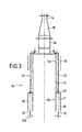
- the percussive core barrel 10 comprises a cylindrical core barrel 12, a plurality of percussive hammers 14 and a drill pipe 16 which extends to the ground surface.
- the core barrel 12 has a vertical axis XX', an upper end 12a, a lower end 12b and a free lower edge 12c.
- the diameter D of the barrel 12 is equal to 1 500 mm in the present example. More generally, this diameter is between 1 and 3 metres.
- the length L of the barrel is equal to 4 metres. More generally, this length is between 3 to 6 metres.
- the machine comprises 8 hammers 14 having a vertical axis and including a body 14a secured to the outer face of the lower end 12b of the barrel and a percussive bit 14b, the bit 14b projecting below the lower edge 12c of the barrel.
- the hammers are regularly angularly disposed around the barrel 12.
- the hammers have a diameter of about 20 cm. These hammers are operated by compressed air at a minimum air pressure of 14 bars. The total volume of air required for the 8 hammers is approximately 155 m 3 /min. As explained hereinafter, the hammers can also be operated by pressurised water or liquid. Additionally, the number of hammers might be different.
- the hammers 14 are located in an annular volume 17 limited by the lower end of the barrel 12, an outer cylindrical shell 18 and an horizontal annular plate 20.
- the compressed air is supplied to the hammers by means of feed pipes 22 which connect the hammers to a compressed air source (not shown) disposed at the ground surface.
- the machine 10 also comprises exhaust pipes 24 which connect the annular volume 17 wherein the hammers are located to a tubular member 26 secured to the upper end of the barrel 12. This tubular member 26 is connected to a frusto conical tubular piece 28 which is secured to the drill pipe 16.
- the machine also comprises a cylindrical spacer ring 30 secured to the barrel 12 and surrounding the upper end 12a of the barrel to act as a guide for the core barrel in the bore.
- a cylindrical spacer ring 30 secured to the barrel 12 and surrounding the upper end 12a of the barrel to act as a guide for the core barrel in the bore.
- the diameter of the outer shell 18 and the spacer ring 30 is slightly less than the diameter of the hole to be bored.
- FIGS 2 and 5 show that the machine is equipped with depth control plates 32. These plates 32 secured to the core barrel extend below the lower edge 12c of the barrel and they are located between the hammer bits 14b. The purpose of these plates is to prevent the bits 14b from penetrating too far into the rock if the hammers 14 are operated without the core barrel being rotated by the drill pipe 16.
- the core barrel 12 is rotated by the drill pipe 16 and the compressed air is supplied to the hammers to operate the bits 14b.
- the bits 14b travel along a circular path around the core tube 12 and the bits 14b bore out a ring of rock, the width thereof corresponds to the size of the bits, leaving a core of rock inside the core tube 12.
- the core of rock When the desired annular bore is obtained, the core of rock may be removed by means of a heavy steel chisel, weighing several tons, which is dropped on to the core of rock to break it into small pieces which can be removed from the hole by a mechanical grab or similar tools. If the depth of the hole required in the rock is more than the internal length L of the barrel 12, boring will be carried out in several stages, the core of rock from each stage being removed before the next stage has begun.
- the compressed air is expelled through the bits 14b and most will return to the ground surface via the exhaust pipes and the drill pipe 16. This air will transport most of the rock cuttings produced by the bits. Some of the air will escape up the outside of the core barrel past the outer shell 18 because the outside diameter of the outer shell is slightly less than the outside diameter of the ring of rock bored out by the bits 14b. However, this will not have a significant detrimental effect on the performance of the percussive core barrel.
- the hammers 14 are operated by compressed air.
- the hammers are operated by hydraulic power and the rock cuttings are still transported by compressed air from the bottom of the hole to the ground surface, therefore a smaller volume of air is required.
- the compressed air feed pipes are detached from the hammers and extended down to the level of the bits, so that air to transport the rock cuttings can be fed down to the bottom of the hole. Most of the air and rock cuttings will return to the ground surface via the exhaust pipes but some will escape up the outside of the core barrel past the outer shell.
- Separate pipes are attached to the hammers 14 to transport the hydraulic fluid used for their operation.
- water is used as hydraulic fluid to operate the hammers and is fed down via the feed pipes to the hammers and expelled through the bits.
- the hole in which the percussive core barrel is being operated is kept full of water to the ground surface by means of a discharge pipe from a suitable water supply.
- Compressed air is fed into the lower part of the machine to cause water and rock cuttings to rise up the exhaust pipes 24 and drill pipe 16 to be discharged at the ground surface.
Landscapes
- Engineering & Computer Science (AREA)
- Geology (AREA)
- Life Sciences & Earth Sciences (AREA)
- Mining & Mineral Resources (AREA)
- Physics & Mathematics (AREA)
- Environmental & Geological Engineering (AREA)
- Fluid Mechanics (AREA)
- General Life Sciences & Earth Sciences (AREA)
- Geochemistry & Mineralogy (AREA)
- Mechanical Engineering (AREA)
- Earth Drilling (AREA)
- External Artificial Organs (AREA)
- Processing And Handling Of Plastics And Other Materials For Molding In General (AREA)
Claims (14)
- Équipement pour forer des trous de grand diamètre dans des roches, comprenant :caractérisé en ce que les moyens formant marteaux (14) sont fixés sur la face extérieure du tube d'âme (12) proche de son extrémité inférieure, de sorte que les têtes (14b) se projettent au-dessous de l'extrémité inférieure du tube, et en ce que des moyens d'échappement sont connectés audit tube d'âme (12) pour collecter le fluide sous pression fourni au voisinage des têtes (14b) et les débris de roche transportés par ledit fluide sous pression depuis le fond du trou vers la surface du sol,un tube d'âme cylindrique (12) ayant un axe vertical, une extrémité supérieure et une extrémité inférieure ;une pluralité de moyens formant marteaux (14) équipés de têtes de percussion (14b) pour pénétrer dans la roche, chaque moyen formant marteau (14) ayant un axe vertical ;des moyens à fluide sous pression (22) pour faire fonctionner lesdits moyens formant marteaux (14) ;des moyens d'alimentation de fluide sous pression pour fournir un fluide sous pression au voisinage des têtes (14b) desdits moyens formant marteaux (14) ; etdes moyens d'entraínement connectés à l'extrémité supérieure dudit tube d'âme (12) pour faire tourner ledit tube d'âme (12) autour de son axe vertical ;
grâce à quoi ledit équipement est en mesure de forer des trous plus profonds que la hauteur moyenne des moyens formant marteaux (14). - Équipement selon la revendication 1, comprenant en outre une coque extérieure cylindrique (18) fixée sur le tube d'âme (12) et entourant l'extrémité inférieure de celui-ci, lesdits moyens formant marteaux (14) étant situés entre ledit tube d'âme (12) et ladite coque extérieure (18).
- Équipement selon la revendication 2, dans lequel lesdits moyens d'échappement comprennent une pluralité de tubes d'échappement (24) ayant des extrémités inférieures, lesdites extrémités inférieures s'ouvrant dans la portion supérieure du volume annulaire limité par le tube d'âme (12) et par la coque extérieure (18).
- Équipement selon la revendication 3, dans lequel lesdits moyens d'entraínement (16) pour faire tourner ledit tube d'âme (12) comprennent un tube de forage vertical (16) fixé sur l'extrémité supérieure du tube d'âme (12) et s'étendant vers la surface du sol.
- Équipement de surface selon la revendication 4, dans lequel lesdits moyens d'échappement comprennent en outre ledit tube de forage vertical (16).
- Équipement selon l'une quelconque des revendications 1 à 5, comprenant en outre une bague d'espacement cylindrique fixée sur la face extérieure dudit tube d'âme (12) et entourant l'extrémité supérieure de celui-ci.
- Équipement selon l'une quelconque des revendications 1 à 6, comprenant en outre une pluralité de moyens de commande de profondeur, lesdits moyens de commande de profondeur étant fixés sur le tube d'âme (12) et se projetant hors de la bordure inférieure dudit tube d'âme (12), lesdits moyens de commande de profondeur étant situés entre lesdits moyens formant marteaux (14).
- Équipement selon l'une quelconque des revendications 1 à 7, dans lequel le nombre des moyens formant marteaux (14) est égal à 4 à 12.
- Équipement selon l'une quelconque des revendications 1 à 8, dans lequel le diamètre du tube d'âme (12) est sensiblement égal à 1500 mm.
- Équipement selon l'une quelconque des revendications 1 à 9, dans lequel la longueur du tube d'âme (12) est sensiblement égale à 4 m.
- Équipement selon l'une quelconque des revendications 1 à 10, dans lequel les moyens formant marteaux (14) fonctionnent avec de l'air comprimé et le fluide sous pression fourni dans le voisinage des têtes de marteaux (14b) est l'air comprimé pour faire fonctionner lesdits moyens formant marteaux (14).
- Équipement selon l'une quelconque des revendications 1 à 10, dans lequel les moyens formant marteaux (14) fonctionnent avec un liquide sous pression et le fluide sous pression fourni dans le voisinage des têtes de marteaux (14b) est l'air comprimé fourni par des tubes s'étendant vers le bas jusqu'au niveau des têtes de marteaux (14b).
- Équipement selon l'une quelconque des revendications 1 à 10, dans lequel les moyens formant marteaux (14) fonctionnent avec un liquide sous pression et le fluide sous pression fourni dans le voisinage des têtes de marteaux (14b) est également le liquide sous pression utilisé pour faire fonctionner les moyens formant marteaux (14).
- Équipement selon l'une quelconque des revendications 1 à 13, dans lequel la longueur L du tube d'âme (12) est strictement supérieure à la hauteur moyenne des moyens formant marteaux (14).
Applications Claiming Priority (2)
| Application Number | Priority Date | Filing Date | Title |
|---|---|---|---|
| GB9821048 | 1998-09-28 | ||
| GBGB9821048.7A GB9821048D0 (en) | 1998-09-28 | 1998-09-28 | Percussive core barrel |
Publications (2)
| Publication Number | Publication Date |
|---|---|
| EP0990765A1 EP0990765A1 (fr) | 2000-04-05 |
| EP0990765B1 true EP0990765B1 (fr) | 2004-04-21 |
Family
ID=10839571
Family Applications (1)
| Application Number | Title | Priority Date | Filing Date |
|---|---|---|---|
| EP99400428A Expired - Lifetime EP0990765B1 (fr) | 1998-09-28 | 1999-02-23 | Tube carottier à percussion |
Country Status (4)
| Country | Link |
|---|---|
| EP (1) | EP0990765B1 (fr) |
| AT (1) | ATE264988T1 (fr) |
| DE (1) | DE69916546D1 (fr) |
| GB (1) | GB9821048D0 (fr) |
Families Citing this family (5)
| Publication number | Priority date | Publication date | Assignee | Title |
|---|---|---|---|---|
| EP2050923B1 (fr) * | 2007-10-15 | 2010-08-11 | TerraSond AG | Dispositif de forage et procédé d'extraction d'échantillons de sol |
| KR100980895B1 (ko) * | 2008-04-15 | 2010-09-10 | 문대영 | 무진동 터널 굴착공법 및 그 장치 |
| WO2012106999A1 (fr) * | 2011-02-11 | 2012-08-16 | Chan Leung Choi | Perforateur de fond de trou à annulaire |
| HK1155608A2 (en) * | 2012-02-10 | 2012-05-18 | Top Mark Mechanical Equipment Limited | Method and apparatus for controlling the operation of cluster drill of down-the-hole hammers |
| WO2020243767A1 (fr) * | 2019-06-04 | 2020-12-10 | Paul Reed | Agencements de forage |
Family Cites Families (7)
| Publication number | Priority date | Publication date | Assignee | Title |
|---|---|---|---|---|
| DE388463C (de) * | 1924-01-14 | Koenig Wilhelm | Vorrichtung zum Bohren von Aufbruechen, Wetterueberhauen u. dgl. | |
| US3297099A (en) * | 1964-05-28 | 1967-01-10 | Ingersoll Rand Co | Rock drill reamer |
| DE2602550A1 (de) * | 1976-01-23 | 1977-07-28 | Preussag Ag | Verfahren zur herstellung von grosslochbohrungen unter einsatz von druckluftbetriebenen bohrlochhaemmern und vorrichtung zur durchfuehrung des verfahrens |
| DE3114612C2 (de) * | 1981-04-07 | 1983-11-10 | Hochstrasser, Jürgen, 6600 Saarbrücken | Bohrvorrichtung für Hartgestein |
| GB2181473B (en) * | 1985-10-04 | 1989-02-01 | Tone Boring Co | Air pressure impact drilling apparatus |
| DE3915538A1 (de) * | 1989-05-12 | 1990-11-15 | Hartfuss Michael | Bohrvorrichtung fuer fels- bzw. hartgestein |
| FR2745031B1 (fr) * | 1996-02-16 | 2000-01-07 | Boniface Andre | Outil a roto-percussion pour creusement de puits de grands diametres en terrain tres dur |
-
1998
- 1998-09-28 GB GBGB9821048.7A patent/GB9821048D0/en not_active Ceased
-
1999
- 1999-02-23 AT AT99400428T patent/ATE264988T1/de not_active IP Right Cessation
- 1999-02-23 DE DE69916546T patent/DE69916546D1/de not_active Expired - Lifetime
- 1999-02-23 EP EP99400428A patent/EP0990765B1/fr not_active Expired - Lifetime
Also Published As
| Publication number | Publication date |
|---|---|
| HK1026933A1 (en) | 2000-12-29 |
| EP0990765A1 (fr) | 2000-04-05 |
| GB9821048D0 (en) | 1998-11-18 |
| DE69916546D1 (de) | 2004-05-27 |
| ATE264988T1 (de) | 2004-05-15 |
Similar Documents
| Publication | Publication Date | Title |
|---|---|---|
| US8857537B2 (en) | Method and apparatus for down-the-hole drilling | |
| US6409432B1 (en) | Downhole hammer-type core barrel and method of using same | |
| CA2818859C (fr) | Perforateur de fond de trou a annulaire | |
| US6892834B1 (en) | Piloted drill barrel and method of using same | |
| KR101302554B1 (ko) | 지반 천공용 해머의 비트 | |
| EP0096037B1 (fr) | Perforatrice hydraulique au rochet | |
| US7555854B2 (en) | Earth auger head and excavation method | |
| JPH10205265A (ja) | 試料採取装置および試料採取方法 | |
| EP0990765A1 (fr) | Tube carottier à percussion | |
| EP2370660B1 (fr) | Procédé et appareil de forage en fond de trou | |
| WO1995033119A1 (fr) | Appareil de forage | |
| CN211573450U (zh) | 一种用于旋挖钻机的清障钻斗 | |
| HK1026933B (en) | Percussive core barrel | |
| KR100372049B1 (ko) | 크레인을 이용한 천공기 | |
| JPH0434231Y2 (fr) | ||
| KR100323302B1 (ko) | 크레인을 이용한 천공기의 배토장치 | |
| JP2003253982A (ja) | 環状掘削装置 | |
| EP2675982B1 (fr) | Procédé et appareil de forage en fond de trou | |
| CN211230227U (zh) | 旋挖集束式潜孔锤的硬岩钻进成桩施工结构 | |
| JPH0340197B2 (fr) | ||
| JP2003214078A (ja) | ケーシングチューブ内の地中障害物の撤去装置 | |
| SU721505A1 (ru) | Установка дл бурени вертикальных выработок | |
| JP3540462B2 (ja) | 打撃破砕式掘削装置の粉塵回収装置 | |
| JP3434068B2 (ja) | 中掘り掘削機 | |
| CN120844925A (zh) | 硬岩旋挖导流滚刀下导向扩孔筒钻钻进施工方法 |
Legal Events
| Date | Code | Title | Description |
|---|---|---|---|
| PUAI | Public reference made under article 153(3) epc to a published international application that has entered the european phase |
Free format text: ORIGINAL CODE: 0009012 |
|
| AK | Designated contracting states |
Kind code of ref document: A1 Designated state(s): AT BE DE DK ES FR GB IT MC NL PT |
|
| AX | Request for extension of the european patent |
Free format text: AL;LT;LV;MK;RO;SI |
|
| 17P | Request for examination filed |
Effective date: 20000907 |
|
| RAP1 | Party data changed (applicant data changed or rights of an application transferred) |
Owner name: COMPAGNIE DU SOL |
|
| AKX | Designation fees paid |
Free format text: AT BE DE DK ES FR GB IT MC NL PT |
|
| 17Q | First examination report despatched |
Effective date: 20021216 |
|
| GRAP | Despatch of communication of intention to grant a patent |
Free format text: ORIGINAL CODE: EPIDOSNIGR1 |
|
| GRAS | Grant fee paid |
Free format text: ORIGINAL CODE: EPIDOSNIGR3 |
|
| GRAA | (expected) grant |
Free format text: ORIGINAL CODE: 0009210 |
|
| AK | Designated contracting states |
Kind code of ref document: B1 Designated state(s): AT BE DE DK ES FR GB IT MC NL PT |
|
| PG25 | Lapsed in a contracting state [announced via postgrant information from national office to epo] |
Ref country code: NL Free format text: LAPSE BECAUSE OF FAILURE TO SUBMIT A TRANSLATION OF THE DESCRIPTION OR TO PAY THE FEE WITHIN THE PRESCRIBED TIME-LIMIT Effective date: 20040421 Ref country code: IT Free format text: LAPSE BECAUSE OF FAILURE TO SUBMIT A TRANSLATION OF THE DESCRIPTION OR TO PAY THE FEE WITHIN THE PRESCRIBED TIME-LIMIT;WARNING: LAPSES OF ITALIAN PATENTS WITH EFFECTIVE DATE BEFORE 2007 MAY HAVE OCCURRED AT ANY TIME BEFORE 2007. THE CORRECT EFFECTIVE DATE MAY BE DIFFERENT FROM THE ONE RECORDED. Effective date: 20040421 Ref country code: BE Free format text: LAPSE BECAUSE OF FAILURE TO SUBMIT A TRANSLATION OF THE DESCRIPTION OR TO PAY THE FEE WITHIN THE PRESCRIBED TIME-LIMIT Effective date: 20040421 Ref country code: AT Free format text: LAPSE BECAUSE OF FAILURE TO SUBMIT A TRANSLATION OF THE DESCRIPTION OR TO PAY THE FEE WITHIN THE PRESCRIBED TIME-LIMIT Effective date: 20040421 |
|
| REG | Reference to a national code |
Ref country code: GB Ref legal event code: FG4D |
|
| REF | Corresponds to: |
Ref document number: 69916546 Country of ref document: DE Date of ref document: 20040527 Kind code of ref document: P |
|
| PG25 | Lapsed in a contracting state [announced via postgrant information from national office to epo] |
Ref country code: DK Free format text: LAPSE BECAUSE OF FAILURE TO SUBMIT A TRANSLATION OF THE DESCRIPTION OR TO PAY THE FEE WITHIN THE PRESCRIBED TIME-LIMIT Effective date: 20040721 |
|
| PG25 | Lapsed in a contracting state [announced via postgrant information from national office to epo] |
Ref country code: DE Free format text: LAPSE BECAUSE OF FAILURE TO SUBMIT A TRANSLATION OF THE DESCRIPTION OR TO PAY THE FEE WITHIN THE PRESCRIBED TIME-LIMIT Effective date: 20040722 |
|
| PG25 | Lapsed in a contracting state [announced via postgrant information from national office to epo] |
Ref country code: ES Free format text: LAPSE BECAUSE OF FAILURE TO SUBMIT A TRANSLATION OF THE DESCRIPTION OR TO PAY THE FEE WITHIN THE PRESCRIBED TIME-LIMIT Effective date: 20040801 |
|
| REG | Reference to a national code |
Ref country code: HK Ref legal event code: GR Ref document number: 1026933 Country of ref document: HK |
|
| NLV1 | Nl: lapsed or annulled due to failure to fulfill the requirements of art. 29p and 29m of the patents act | ||
| ET | Fr: translation filed | ||
| PLBE | No opposition filed within time limit |
Free format text: ORIGINAL CODE: 0009261 |
|
| STAA | Information on the status of an ep patent application or granted ep patent |
Free format text: STATUS: NO OPPOSITION FILED WITHIN TIME LIMIT |
|
| PG25 | Lapsed in a contracting state [announced via postgrant information from national office to epo] |
Ref country code: MC Free format text: LAPSE BECAUSE OF NON-PAYMENT OF DUE FEES Effective date: 20050228 |
|
| 26N | No opposition filed |
Effective date: 20050124 |
|
| PG25 | Lapsed in a contracting state [announced via postgrant information from national office to epo] |
Ref country code: PT Free format text: LAPSE BECAUSE OF NON-PAYMENT OF DUE FEES Effective date: 20040921 |
|
| REG | Reference to a national code |
Ref country code: FR Ref legal event code: PLFP Year of fee payment: 17 |
|
| PGFP | Annual fee paid to national office [announced via postgrant information from national office to epo] |
Ref country code: GB Payment date: 20150123 Year of fee payment: 17 Ref country code: FR Payment date: 20150220 Year of fee payment: 17 |
|
| GBPC | Gb: european patent ceased through non-payment of renewal fee |
Effective date: 20160223 |
|
| REG | Reference to a national code |
Ref country code: FR Ref legal event code: ST Effective date: 20161028 |
|
| PG25 | Lapsed in a contracting state [announced via postgrant information from national office to epo] |
Ref country code: GB Free format text: LAPSE BECAUSE OF NON-PAYMENT OF DUE FEES Effective date: 20160223 Ref country code: FR Free format text: LAPSE BECAUSE OF NON-PAYMENT OF DUE FEES Effective date: 20160229 |