EP0990772A2 - Dispositif et méthode de refroidissement d'une paroi dont la surface extérieure est en contact avec un courant de gaz chaud - Google Patents
Dispositif et méthode de refroidissement d'une paroi dont la surface extérieure est en contact avec un courant de gaz chaud Download PDFInfo
- Publication number
- EP0990772A2 EP0990772A2 EP99810803A EP99810803A EP0990772A2 EP 0990772 A2 EP0990772 A2 EP 0990772A2 EP 99810803 A EP99810803 A EP 99810803A EP 99810803 A EP99810803 A EP 99810803A EP 0990772 A2 EP0990772 A2 EP 0990772A2
- Authority
- EP
- European Patent Office
- Prior art keywords
- cooling
- wall
- recesses
- insert
- recess
- Prior art date
- Legal status (The legal status is an assumption and is not a legal conclusion. Google has not performed a legal analysis and makes no representation as to the accuracy of the status listed.)
- Withdrawn
Links
Images

Classifications
-
- F—MECHANICAL ENGINEERING; LIGHTING; HEATING; WEAPONS; BLASTING
- F01—MACHINES OR ENGINES IN GENERAL; ENGINE PLANTS IN GENERAL; STEAM ENGINES
- F01D—NON-POSITIVE DISPLACEMENT MACHINES OR ENGINES, e.g. STEAM TURBINES
- F01D5/00—Blades; Blade-carrying members; Heating, heat-insulating, cooling or antivibration means on the blades or the members
- F01D5/12—Blades
- F01D5/14—Form or construction
- F01D5/18—Hollow blades, i.e. blades with cooling or heating channels or cavities; Heating, heat-insulating or cooling means on blades
- F01D5/187—Convection cooling
- F01D5/188—Convection cooling with an insert in the blade cavity to guide the cooling fluid, e.g. forming a separation wall
- F01D5/189—Convection cooling with an insert in the blade cavity to guide the cooling fluid, e.g. forming a separation wall the insert having a tubular cross-section, e.g. airfoil shape
Definitions
- the invention relates to a device and a method for cooling a one-sided wall surrounded by hot gas, in particular the hollow profile body Gas turbine blade, according to the preamble of claim 1.
- the blown-out cooling air must be as quick as possible are diverted and flow protectively along the profile surface. Around Protecting the areas between the wells is also one rapid lateral expansion of the cooling air required.
- the mixing areas of the hot gas with the cooling air jets creates a wide variety of vortices, which is of crucial importance for the protective effect of a cooling configuration have.
- kidney vertebra i.e. one out of one a pair of vertebrae consisting of right and left rotating vertebrae.
- this kidney vertebra transports part of the hot gas between the Drilled holes directly on the profile surface of the turbine blade and thus below the cooling air jets, which proves to be a serious disadvantage.
- a serious disadvantage of this solution is the weak intensity of the inner vertebra, so that it dissolves relatively quickly and not permanently for improvement the cooling effectiveness can be used.
- DE 196 12 840 A1 has already been known to improve this. To do this, in the cooling cavity, upstream of the cooling hole, a rib arranged and the cooling insert in the area the cooling holes are deformed in the direction of the wall to be cooled. In this way can the inflow of the cooling fluid into the cooling holes and thus the cooling effectiveness be improved.
- the invention tries to avoid all these disadvantages. It is based on the task a device and a corresponding method for cooling a Wall surrounded by hot gas on one side with a further improved cooling effect to accomplish.
- this is achieved in that with a device according to the preamble of claim 1, in the cooling cavity, upstream of each recess, a deflection element for the cooling fluid opening into the latter is arranged.
- the Deflection element is also opposite the cooling cavity by means of side walls completed.
- the cooling fluid not captured by the deflection elements can be relative flow undisturbed between the adjacent deflection elements.
- the individual deflection elements act as cooling fins, which also makes the convective Cooling of the wall in the area between the recesses improved becomes. The conclusion is not only the film cooling, but the whole Cooling of the wall significantly improved. This can save cooling air and are used elsewhere.
- a wall cooled in this way can not only be used as a hollow profile body of a gas turbine blade trained, but also advantageously as a combustion chamber wall or can be used as a heat accumulation segment of a gas turbine.
- each recess has a central axis and each Deflection element has a deflection surface, each deflection surface directly upstream of the associated recess at least approximately parallel to Center axis of this recess is aligned.
- the deflection surface is curved and one at least approximately constant radius of curvature.
- deflection elements connected to the wall and are also on Cooling insert, they also advantageously serve as a spacer between the one to be cooled Wall and the cooling insert.
- the guide vane 1 of a gas turbine consists of a hollow profile body 2, the one Wall 3 formed as an outer jacket, one arranged at a distance from it Cooling insert 4 and a cooling cavity 5 formed between the two.
- a blade cavity 6 is formed in the interior of the cooling insert 4, which in a conventional manner with the compressor of the gas turbine system, not shown is connected and acted upon by this as cooling fluid 7 cooling air becomes.
- the outer jacket 3 has an outer and an inner surface 8, 9, between which several rows of recesses designed as cooling bores 10 are arranged.
- the blade cavity 6 is in several Cooling insert 4 arranged openings 11 connected to the cooling cavity 5 (Fig. 1).
- the guide vane 1 can also only have a single row of cooling bores Own 10.
- hot gas 12 does not flow out of the Combustion chamber shown on the guide vanes 1 and also not shown Blades of the gas turbine. Therefore, they have to be constantly cooled.
- the cooling of the guide blades 1 takes place by means of those brought up by the compressor Cooling air 7, this via the openings 11 of the cooling insert 4 in penetrates the cooling cavity 5 and first the inner surface 9 of the outer jacket 3 convectively cools. Then the cooling air 7 through the cooling holes 10 in a plurality of cooling air jets on the outer surface 8 the outer shell 3 blown out.
- the curvature of these cooling air jets at her Exit into the main flow of hot gas 12 occurs at an exit angle 13 of about 30 °.
- FIG. 3 shows an enlarged section of a design according to the invention Guide vane 1 shown.
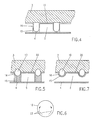
- this guide vane 1 is upstream in the cooling cavity 5 each row of cooling bores 10, a deflecting element opening into the latter 15 arranged for the cooling fluid 7 and by means of side walls 16 opposite the Cooling cavity 5 completed (Fig. 4, Fig. 5).
- Each cooling hole 10 has one Central axis 17 and each deflecting element 15 have a deflecting surface 18. It is each deflecting surface 18 approximately upstream of the associated cooling bore 10 aligned parallel to the central axis 17 of this cooling bore 10.
- the deflection surface 18 is curved and has an approximately continuous Radius of curvature r.
- the latter which is the transition radius from Cooling insert 4 to the cooling bore 10 corresponds to one at an angle of 30 ° trained cooling bore 10 about 15 times the diameter d of the associated Cooling hole 10 (Fig. 3). With larger distances between the cooling insert 4 the wall 3, the transition radii are larger, with larger exit angles 13 however smaller.
- the deflection elements assigned to a row of cooling bores 10 15 are connected via a wall-side web 19 to a deflection insert 20 connected (Fig. 4, Fig. 5, Fig. 7).
- the deflection elements 15 are made of solid material, connected to the wall 3 and are also on the cooling insert 4. Every deflection element 15 thus simultaneously forms a spacer between the cooling insert 4 and the wall to be cooled 3.
- Figure 7 is a second embodiment of the invention with one of a deep-drawn sheet metal deflection element 15 or a corresponding Deflection insert 20 shown.
- the function of this solution is essentially analogous to the first embodiment.
- Such a cooling configuration is of course not on the guide vanes 1 of gas turbines limited. It can also be used for blades, combustion chamber walls, Heat accumulation segments of gas turbines or others, one side of hot gas 12 surrounding walls 3 are used.
Landscapes
- Engineering & Computer Science (AREA)
- Mechanical Engineering (AREA)
- General Engineering & Computer Science (AREA)
- Turbine Rotor Nozzle Sealing (AREA)
- Heat-Exchange Devices With Radiators And Conduit Assemblies (AREA)
Applications Claiming Priority (2)
| Application Number | Priority Date | Filing Date | Title |
|---|---|---|---|
| DE19845147 | 1998-10-01 | ||
| DE1998145147 DE19845147B4 (de) | 1998-10-01 | 1998-10-01 | Vorrichtung und Verfahren zur Kühlung einer einseitug von Heißgas umgebenen Wand |
Publications (2)
| Publication Number | Publication Date |
|---|---|
| EP0990772A2 true EP0990772A2 (fr) | 2000-04-05 |
| EP0990772A3 EP0990772A3 (fr) | 2001-10-04 |
Family
ID=7883001
Family Applications (1)
| Application Number | Title | Priority Date | Filing Date |
|---|---|---|---|
| EP99810803A Withdrawn EP0990772A3 (fr) | 1998-10-01 | 1999-09-07 | Dispositif et méthode de refroidissement d'une paroi dont la surface extérieure est en contact avec un courant de gaz chaud |
Country Status (2)
| Country | Link |
|---|---|
| EP (1) | EP0990772A3 (fr) |
| DE (1) | DE19845147B4 (fr) |
Cited By (2)
| Publication number | Priority date | Publication date | Assignee | Title |
|---|---|---|---|---|
| DE19845147B4 (de) * | 1998-10-01 | 2006-11-23 | Alstom | Vorrichtung und Verfahren zur Kühlung einer einseitug von Heißgas umgebenen Wand |
| EP3176374A1 (fr) * | 2015-12-03 | 2017-06-07 | General Electric Company | Refroidissement de bord de fuite pour une pale de turbine |
Families Citing this family (1)
| Publication number | Priority date | Publication date | Assignee | Title |
|---|---|---|---|---|
| JP4191578B2 (ja) * | 2003-11-21 | 2008-12-03 | 三菱重工業株式会社 | ガスタービンエンジンのタービン冷却翼 |
Citations (2)
| Publication number | Priority date | Publication date | Assignee | Title |
|---|---|---|---|---|
| EP0258754A2 (fr) | 1986-09-03 | 1988-03-09 | Mtu Motoren- Und Turbinen-Union MàNchen Gmbh | Aube de turbine avec noyau de refroidissement |
| DE19612840A1 (de) | 1996-03-30 | 1997-10-02 | Abb Research Ltd | Vorrichtung und Verfahren zur Kühlung einer einseitig von Heissgas umgebenen Wand |
Family Cites Families (6)
| Publication number | Priority date | Publication date | Assignee | Title |
|---|---|---|---|---|
| US2782597A (en) * | 1952-03-15 | 1957-02-26 | Gen Electric | Combustion chamber having improved air inlet means |
| DE1199541B (de) * | 1961-12-04 | 1965-08-26 | Jan Jerie Dr Ing | Sammler von Treibgasen fuer das Leitrad von Gasturbinen |
| AT237973B (de) * | 1961-12-04 | 1965-01-25 | Jan Ing Dr Jerie | Sammler von Treibgasen für das Leitrad der Gasturbine |
| US5407133A (en) * | 1989-12-26 | 1995-04-18 | United Technologies Corporation | Cooled thin metal liner |
| US5271715A (en) * | 1992-12-21 | 1993-12-21 | United Technologies Corporation | Cooled turbine blade |
| DE19845147B4 (de) * | 1998-10-01 | 2006-11-23 | Alstom | Vorrichtung und Verfahren zur Kühlung einer einseitug von Heißgas umgebenen Wand |
-
1998
- 1998-10-01 DE DE1998145147 patent/DE19845147B4/de not_active Expired - Fee Related
-
1999
- 1999-09-07 EP EP99810803A patent/EP0990772A3/fr not_active Withdrawn
Patent Citations (2)
| Publication number | Priority date | Publication date | Assignee | Title |
|---|---|---|---|---|
| EP0258754A2 (fr) | 1986-09-03 | 1988-03-09 | Mtu Motoren- Und Turbinen-Union MàNchen Gmbh | Aube de turbine avec noyau de refroidissement |
| DE19612840A1 (de) | 1996-03-30 | 1997-10-02 | Abb Research Ltd | Vorrichtung und Verfahren zur Kühlung einer einseitig von Heissgas umgebenen Wand |
Non-Patent Citations (1)
| Title |
|---|
| G. WILFERT: "Dissertationsschrift zum Thema "Experimentelle und numerische Untersuchungen derMischungsvorgänge zwischen Kühlfilmen und Gitterströmung an einem hochbelastetenTurbinengitter", 1994, MONCHEN, pages: 54/70-74 |
Cited By (4)
| Publication number | Priority date | Publication date | Assignee | Title |
|---|---|---|---|---|
| DE19845147B4 (de) * | 1998-10-01 | 2006-11-23 | Alstom | Vorrichtung und Verfahren zur Kühlung einer einseitug von Heißgas umgebenen Wand |
| EP3176374A1 (fr) * | 2015-12-03 | 2017-06-07 | General Electric Company | Refroidissement de bord de fuite pour une pale de turbine |
| US10344598B2 (en) | 2015-12-03 | 2019-07-09 | General Electric Company | Trailing edge cooling for a turbine blade |
| US11208901B2 (en) | 2015-12-03 | 2021-12-28 | General Electric Company | Trailing edge cooling for a turbine blade |
Also Published As
| Publication number | Publication date |
|---|---|
| DE19845147B4 (de) | 2006-11-23 |
| EP0990772A3 (fr) | 2001-10-04 |
| DE19845147A1 (de) | 2000-04-06 |
Similar Documents
| Publication | Publication Date | Title |
|---|---|---|
| EP0798448B1 (fr) | Système et dispositif pour réfroidir une paroi chauffée d'un côté par un gaz chaud | |
| DE10001109B4 (de) | Gekühlte Schaufel für eine Gasturbine | |
| EP0899425B1 (fr) | Aube pour une turbine à gaz | |
| DE69006433T3 (de) | Turbinenschaufel. | |
| DE1946535C3 (de) | Bauteil für ein Gasturbinentriebwerk | |
| DE19921644B4 (de) | Kühlbare Schaufel für eine Gasturbine | |
| EP0985802B1 (fr) | Méthode de formation d'un orifice pour le refroidissement par pellicule | |
| DE3211139C1 (de) | Axialturbinenschaufel,insbesondere Axialturbinenlaufschaufel fuer Gasturbinentriebwerke | |
| DE69932688T2 (de) | Kühlungsöffnungen für Gasturbinenkomponenten | |
| EP0945593B1 (fr) | Trou de refroidissement pelliculaire | |
| DE2930949C2 (fr) | ||
| EP1320661B1 (fr) | Aube de turbine a gaz | |
| DE69412056T2 (de) | Gekühlte Gasturbinenschaufel | |
| DE4441507A1 (de) | Turbinenkühlschaufel | |
| DE2042947A1 (de) | Schaufelanordnung mit Kühlvorrichtung | |
| DE3231689A1 (de) | Mehrfach prallgekuehltes gebilde, insbesondere ummantelung eines gasstroemungsweges | |
| DE102006004437A1 (de) | Plattform einer Laufschaufel einer Gasturbine, Verfahren zur Herstellung einer Laufschaufel, Dichtungsplatte und Gasturbine | |
| DE2657405A1 (de) | Oberflaechenkuehlvorrichtung, insbesondere fuer gasturbinentriebwerke | |
| DE102005044183A1 (de) | Vorrichtung und Verfahren zur Kühlung von Turbinenschaufelplattformen | |
| DE3210626C2 (fr) | ||
| DE1601561B2 (de) | Gekühlte Schaufel mit Tragflächenprofil für eine Axialströmungsmaschine | |
| EP2087207B1 (fr) | Aube de turbine | |
| DE2643049A1 (de) | Schaufel mit gekuehlter plattform fuer eine stroemungsmaschine | |
| DE102018108729B4 (de) | Strömungsführende Komponente mit einer Strömungsleitfläche sowie eine Gasturbinenschaufel | |
| EP0954680B1 (fr) | Aube de turbine et son utilisation dans un systeme de turbine a gaz |
Legal Events
| Date | Code | Title | Description |
|---|---|---|---|
| PUAI | Public reference made under article 153(3) epc to a published international application that has entered the european phase |
Free format text: ORIGINAL CODE: 0009012 |
|
| AK | Designated contracting states |
Kind code of ref document: A2 Designated state(s): AT BE CH CY DE DK ES FI FR GB GR IE IT LI LU MC NL PT SE |
|
| AX | Request for extension of the european patent |
Free format text: AL;LT;LV;MK;RO;SI |
|
| RIN1 | Information on inventor provided before grant (corrected) |
Inventor name: HERMANN, CARSTEN Inventor name: WILFERT, GUENTER, DR |
|
| PUAL | Search report despatched |
Free format text: ORIGINAL CODE: 0009013 |
|
| AK | Designated contracting states |
Kind code of ref document: A3 Designated state(s): AT BE CH CY DE DK ES FI FR GB GR IE IT LI LU MC NL PT SE |
|
| AX | Request for extension of the european patent |
Free format text: AL;LT;LV;MK;RO;SI |
|
| AKX | Designation fees paid | ||
| REG | Reference to a national code |
Ref country code: DE Ref legal event code: 8566 |
|
| STAA | Information on the status of an ep patent application or granted ep patent |
Free format text: STATUS: THE APPLICATION IS DEEMED TO BE WITHDRAWN |
|
| 18D | Application deemed to be withdrawn |
Effective date: 20020402 |