EP0990814A2 - Frein à réglage automatique - Google Patents
Frein à réglage automatique Download PDFInfo
- Publication number
- EP0990814A2 EP0990814A2 EP99119310A EP99119310A EP0990814A2 EP 0990814 A2 EP0990814 A2 EP 0990814A2 EP 99119310 A EP99119310 A EP 99119310A EP 99119310 A EP99119310 A EP 99119310A EP 0990814 A2 EP0990814 A2 EP 0990814A2
- Authority
- EP
- European Patent Office
- Prior art keywords
- lever
- brake
- adjustment nut
- pawl
- transaxle
- Prior art date
- Legal status (The legal status is an assumption and is not a legal conclusion. Google has not performed a legal analysis and makes no representation as to the accuracy of the status listed.)
- Withdrawn
Links
- 230000007246 mechanism Effects 0.000 claims abstract description 11
- 230000005540 biological transmission Effects 0.000 claims description 10
- 230000000737 periodic effect Effects 0.000 description 2
- 230000002250 progressing effect Effects 0.000 description 2
- 230000006978 adaptation Effects 0.000 description 1
- 230000000694 effects Effects 0.000 description 1
- 230000002706 hydrostatic effect Effects 0.000 description 1
- 238000009434 installation Methods 0.000 description 1
- 230000000750 progressive effect Effects 0.000 description 1
- 238000003466 welding Methods 0.000 description 1
Images


Classifications
-
- F—MECHANICAL ENGINEERING; LIGHTING; HEATING; WEAPONS; BLASTING
- F16—ENGINEERING ELEMENTS AND UNITS; GENERAL MEASURES FOR PRODUCING AND MAINTAINING EFFECTIVE FUNCTIONING OF MACHINES OR INSTALLATIONS; THERMAL INSULATION IN GENERAL
- F16D—COUPLINGS FOR TRANSMITTING ROTATION; CLUTCHES; BRAKES
- F16D65/00—Parts or details
- F16D65/14—Actuating mechanisms for brakes; Means for initiating operation at a predetermined position
- F16D65/16—Actuating mechanisms for brakes; Means for initiating operation at a predetermined position arranged in or on the brake
- F16D65/18—Actuating mechanisms for brakes; Means for initiating operation at a predetermined position arranged in or on the brake adapted for drawing members together, e.g. for disc brakes
-
- B—PERFORMING OPERATIONS; TRANSPORTING
- B60—VEHICLES IN GENERAL
- B60K—ARRANGEMENT OR MOUNTING OF PROPULSION UNITS OR OF TRANSMISSIONS IN VEHICLES; ARRANGEMENT OR MOUNTING OF PLURAL DIVERSE PRIME-MOVERS IN VEHICLES; AUXILIARY DRIVES FOR VEHICLES; INSTRUMENTATION OR DASHBOARDS FOR VEHICLES; ARRANGEMENTS IN CONNECTION WITH COOLING, AIR INTAKE, GAS EXHAUST OR FUEL SUPPLY OF PROPULSION UNITS IN VEHICLES
- B60K17/00—Arrangement or mounting of transmissions in vehicles
- B60K17/04—Arrangement or mounting of transmissions in vehicles characterised by arrangement, location or kind of gearing
- B60K17/06—Arrangement or mounting of transmissions in vehicles characterised by arrangement, location or kind of gearing of change-speed gearing
- B60K17/08—Arrangement or mounting of transmissions in vehicles characterised by arrangement, location or kind of gearing of change-speed gearing of mechanical type
-
- B—PERFORMING OPERATIONS; TRANSPORTING
- B60—VEHICLES IN GENERAL
- B60K—ARRANGEMENT OR MOUNTING OF PROPULSION UNITS OR OF TRANSMISSIONS IN VEHICLES; ARRANGEMENT OR MOUNTING OF PLURAL DIVERSE PRIME-MOVERS IN VEHICLES; AUXILIARY DRIVES FOR VEHICLES; INSTRUMENTATION OR DASHBOARDS FOR VEHICLES; ARRANGEMENTS IN CONNECTION WITH COOLING, AIR INTAKE, GAS EXHAUST OR FUEL SUPPLY OF PROPULSION UNITS IN VEHICLES
- B60K17/00—Arrangement or mounting of transmissions in vehicles
- B60K17/04—Arrangement or mounting of transmissions in vehicles characterised by arrangement, location or kind of gearing
- B60K17/16—Arrangement or mounting of transmissions in vehicles characterised by arrangement, location or kind of gearing of differential gearing
-
- F—MECHANICAL ENGINEERING; LIGHTING; HEATING; WEAPONS; BLASTING
- F16—ENGINEERING ELEMENTS AND UNITS; GENERAL MEASURES FOR PRODUCING AND MAINTAINING EFFECTIVE FUNCTIONING OF MACHINES OR INSTALLATIONS; THERMAL INSULATION IN GENERAL
- F16D—COUPLINGS FOR TRANSMITTING ROTATION; CLUTCHES; BRAKES
- F16D65/00—Parts or details
- F16D65/38—Slack adjusters
- F16D65/40—Slack adjusters mechanical
- F16D65/52—Slack adjusters mechanical self-acting in one direction for adjusting excessive play
- F16D65/56—Slack adjusters mechanical self-acting in one direction for adjusting excessive play with screw-thread and nut
- F16D65/567—Slack adjusters mechanical self-acting in one direction for adjusting excessive play with screw-thread and nut for mounting on a disc brake
-
- F—MECHANICAL ENGINEERING; LIGHTING; HEATING; WEAPONS; BLASTING
- F16—ENGINEERING ELEMENTS AND UNITS; GENERAL MEASURES FOR PRODUCING AND MAINTAINING EFFECTIVE FUNCTIONING OF MACHINES OR INSTALLATIONS; THERMAL INSULATION IN GENERAL
- F16H—GEARING
- F16H3/00—Toothed gearings for conveying rotary motion with variable gear ratio or for reversing rotary motion
- F16H3/02—Toothed gearings for conveying rotary motion with variable gear ratio or for reversing rotary motion without gears having orbital motion
- F16H3/08—Toothed gearings for conveying rotary motion with variable gear ratio or for reversing rotary motion without gears having orbital motion exclusively or essentially with continuously meshing gears, that can be disengaged from their shafts
- F16H3/083—Toothed gearings for conveying rotary motion with variable gear ratio or for reversing rotary motion without gears having orbital motion exclusively or essentially with continuously meshing gears, that can be disengaged from their shafts with radially acting and axially controlled clutching members, e.g. sliding keys
-
- F—MECHANICAL ENGINEERING; LIGHTING; HEATING; WEAPONS; BLASTING
- F16—ENGINEERING ELEMENTS AND UNITS; GENERAL MEASURES FOR PRODUCING AND MAINTAINING EFFECTIVE FUNCTIONING OF MACHINES OR INSTALLATIONS; THERMAL INSULATION IN GENERAL
- F16D—COUPLINGS FOR TRANSMITTING ROTATION; CLUTCHES; BRAKES
- F16D2125/00—Components of actuators
- F16D2125/18—Mechanical mechanisms
- F16D2125/20—Mechanical mechanisms converting rotation to linear movement or vice versa
- F16D2125/34—Mechanical mechanisms converting rotation to linear movement or vice versa acting in the direction of the axis of rotation
- F16D2125/36—Helical cams, Ball-rotating ramps
Definitions
- the present invention relates to brake systems of small transmissions and transaxles for riding lawn mowers, garden tractors, and the like. More specifically, the field of the invention is that of self-adjusting brakes for such small transmissions and transaxles.
- Prior art self-adjusting brake systems have utilized the general concept of a ratcheting mechanism for automatic adjustment to compensate for brake wear.
- the ratcheting mechanisms generally consist of a spring-controlled brake lever with ratchet cogs which engage with the teeth of a wheel fixed to a shaft. With successive wear of the braking system, the ratchet cogs engage in new teeth, causing rotation of the wheel, and adjustment of the braking system inward to compensate for wear.
- the ratcheting systems in the prior art also include a multitude of specialized, custom parts to accomplish the self-adjusting braking capability.
- a self-adjusting brake system for small transmissions such as those used on lawn tractors, garden tractors, and the like is needed to reduce the amount of periodic adjustments required to the brake system.
- a self-adjusting brake system which eliminates the need for expensive custom parts, and which uses existing hardware, is needed to allow for a simple, cost-effective improvement to existing brake systems.
- the present invention is a self-adjusting brake system which utilizes an extremely simple ratcheting mechanism in combination with an existing brake lever, which is operably connected to the shift shaft, or other shaft or axle of a transaxle.
- the ratcheting mechanism consists of a nut with external teeth and grooves which contact the brake lever.
- a hole in the lower portion of the brake lever contains a pawl which contacts the external teeth of the nut, and engages successive teeth with progressive wear of the brakes. As the brakes are worn, and the pawl engages in successive teeth, the braking system is adjusted inward, thus eliminating the need for periodic brake adjustment over time.
- the self-adjusting brake system uses existing hardware of transaxle braking systems, and requires the addition of minimal modified standard parts to achieve the ratcheting action.
- the self-adjusting brake system prolongs the uninterrupted use of the braking system without adjustments thereof.
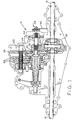
- transaxle 12 as disclosed in U.S. Patent 4,966,574, the disclosure of which is explicitly incorporated, comprises a lower housing 14 with an upper housing (not shown), said housings supporting axles 16 and 18, on which wheels (not shown) are mounted.
- the transaxle 12 comprises a speed reduction mechanism including shift shaft 20, counter shaft 22, and brake shaft 23.
- Bevel gear 24 is turned by an input shaft (not shown) and engages gear 26 of counter shaft 22.
- Companion gears 28 of counter shaft 20 engage spur gears 30 of shift shaft 20 so that gear 32 of shift shaft 20 drives ring gear 34 of differential 36 thus turning axles 16 and 18.
- the vehicle is slowed or stopped by brake assembly 38 through action of brake lever 40, applying braking torque to brake shaft 23.
- the transaxle 12 could be of a conventional hydrostatic design, such as disclosed in U.S. Patent No. 5,392,603, which is expressly incorporated by reference.
- one embodiment of the present invention includes brake lever 40 connected to brake assembly 38 on mounting bolt 50 and held in position by torsion spring 52 and ratchet nut 54.
- Brake pins 56 are in contact with cam surface 53 of brake lever 40 at their outer end, and are in contact with plate 58 at their inner end.
- Plate 58 is in contact with outer brake pad 60.
- Inner and outer brake pads 60 and 64 surround brake disc 62, and brake disc 62 is splined to brake shaft 23.
- Mounting bolt 50 is fixed to brake housing 70.
- brake lever 40 Upon rotation of brake lever 40 about mounting bolt 50, cam surface 53 engages brake pins 56 and thereby presses outer brake pad 60 inwardly towards brake disc 62. A slight end play permits brake disc 62 to move into inner brake pad 64 such that brake disc 62 is in effect squeezed between brake pads 60 and 64 upon movement of brake lever 40. Pressing of brake pads 60 and 64 against brake disc 62 causes slowing or stopping of brake disc 62 and brake shaft 23, resulting in subsequent slowing or stopping of axles 16 and 18 and the mounted wheels (not shown).
- ratchet nut 54 is positioned on mounting bolt 50 against anti-rotation bracket 66, thrust washer 68, and brake lever 40.
- Anti-rotation bracket 66 is located adjacent to ratchet nut 54 and prevents ratchet nut 54 from backing off during operation through attachment to brake housing 70 by bolt 72.
- Thrust washer 68 is located adjacent to anti-rotation bracket 66 and provides a larger, evenly distributed pressure upon tightening of ratchet nut 54.
- brake lever 40 includes a unidirectional pawl 74, and ratchet nut 54 includes preferably twelve (12), but possibly eight (8) grooves 82, forming teeth 83.
- Figure 4 shows engagement of pawl 74 of brake lever 40 with teeth 83 of ratchet nut 54 during application of braking force, or clockwise rotation of brake lever 40.
- Figure 5 shows progression of pawl 74 of brake lever 40 past teeth 83 of ratchet nut 54, progressing to the next successive groove 82 of ratchet nut 54 when braking force is released, or counterclockwise rotation of brake lever 40.
- brake lever 40 could include the grooves 82 and teeth 83, and ratchet nut 54 could include the pawl 74, to provide the required ratcheting action.
- Ratchet nut 54 is shown in detail in Figs. 6 and 7, having shaft 76, collar 78, head 80, grooves 82, teeth 83, and threaded inner bore 84.
- Shaft 76 comprises grooves 82 and teeth 83 which interact with pawl 74 of brake lever 40.
- Collar 78 provides clamp-up pressure to adjust the position of brake lever 40 inward when ratchet nut 54 is rotated by brake lever 40.
- Head 80 and threaded inner bore 84 are used for installation and removal of ratchet nut 54 over mounting bolt 50.
- FIG. 8 A second embodiment of the present invention is shown in Figs. 8 and 12, which comprises adjuster block 86 attached to brake lever 40 at fixed connection 90, ratchet block 88, retaining snap ring 100 and threaded locknut 92.
- Adjuster block 86 is joined at fixed connection 90, for example by welding, with brake lever 40 such that movement of brake lever 40 causes simultaneous movement of adjuster block 86.
- Ratchet block 88 is detailed in Figs. 10 and 11, and comprises nut recess 98, ratchet pawls 96, and a retaining ring groove.
- Nut recess 98 is shaped to mate with locknut 92, such that rotation of ratchet block 88 causes contact between nut recess 98 and locknut 92, thereby turning locknut 92 simultaneously with ratchet block 88.
- Retaining ring 100 provides positioning of ratchet block 88 along mounting bolt 50 with rotation of ratchet block 88.
- adjuster block 86 moves simultaneously with brake lever 40 due to fixed connection 90, and pawl or lug 94 of adjuster block 86 engages a ratchet tooth 96 of ratchet block 88, turning ratchet block 88 and locknut 92. Clockwise rotation of ratchet block 88 and locknut 92 then causes inward movement of adjuster block 86 and brake lever 40 along mounting bolt 50. As brake lever 40 is released or rotated counterclockwise, ratchet block 88 and locknut 92 stay in place.
- lug 94 of adjuster block 86 rides over cam surface 95 and moves past the next successive ratchet tooth 96 in ratchet block 88 when brake lever 40 is released, or rotated counterclockwise, thus rotating ratchet block 88 clockwise on the next brake engagement and adjusting surface 53 of brake lever 40 inward to provide the necessary braking force.
Landscapes
- Engineering & Computer Science (AREA)
- General Engineering & Computer Science (AREA)
- Mechanical Engineering (AREA)
- Chemical & Material Sciences (AREA)
- Combustion & Propulsion (AREA)
- Transportation (AREA)
- Braking Arrangements (AREA)
Applications Claiming Priority (2)
| Application Number | Priority Date | Filing Date | Title |
|---|---|---|---|
| US165904 | 1993-12-14 | ||
| US09/165,904 US6123182A (en) | 1998-10-02 | 1998-10-02 | Self-adjustable brake |
Publications (2)
| Publication Number | Publication Date |
|---|---|
| EP0990814A2 true EP0990814A2 (fr) | 2000-04-05 |
| EP0990814A3 EP0990814A3 (fr) | 2002-10-16 |
Family
ID=22600957
Family Applications (1)
| Application Number | Title | Priority Date | Filing Date |
|---|---|---|---|
| EP99119310A Withdrawn EP0990814A3 (fr) | 1998-10-02 | 1999-09-29 | Frein à réglage automatique |
Country Status (3)
| Country | Link |
|---|---|
| US (1) | US6123182A (fr) |
| EP (1) | EP0990814A3 (fr) |
| CA (1) | CA2283618C (fr) |
Cited By (1)
| Publication number | Priority date | Publication date | Assignee | Title |
|---|---|---|---|---|
| WO2010123363A1 (fr) * | 2009-04-23 | 2010-10-28 | Teunis Karel Van Ee | Transmission |
Families Citing this family (6)
| Publication number | Priority date | Publication date | Assignee | Title |
|---|---|---|---|---|
| US6454673B1 (en) | 2000-10-12 | 2002-09-24 | Tecumseh Products Company | Self adjusting wet brake for use with a transmission or transaxle |
| CA2381370C (fr) * | 2001-04-11 | 2005-10-25 | Tecumseh Products Company | Frein pour boite-pont |
| US6571554B2 (en) | 2001-04-25 | 2003-06-03 | Tecumseh Products Company | Hydrostatic transmission having hydraulic dampening and neutral bleed mechanism |
| NL1026482C2 (nl) * | 2004-06-01 | 2005-12-05 | Fountain Tech Bv | Verpakking voor informatiedragers. |
| CN100445589C (zh) * | 2006-12-28 | 2008-12-24 | 浙江亚特电器有限公司 | 电动工具的离合器 |
| CN115013520B (zh) * | 2022-06-17 | 2024-05-17 | 潍柴动力股份有限公司 | Amt变速箱中间轴制动控制方法、装置及控制器 |
Family Cites Families (23)
| Publication number | Priority date | Publication date | Assignee | Title |
|---|---|---|---|---|
| US3129789A (en) * | 1960-06-25 | 1964-04-21 | Dunlop Rubber Co | Brakes and wear compensating mechanism for brakes |
| GB968897A (en) * | 1961-11-08 | 1964-09-09 | Automotive Prod Co Ltd | Improvements in or relating to disc brakes |
| US3243016A (en) * | 1964-06-25 | 1966-03-29 | Kelsey Hayes Co | Combined hydraulic and mechanical brake |
| FR96531E (fr) * | 1968-11-29 | 1972-10-20 | Air Liquide | Perfectionnement au procédé de blanchiment des textiles. |
| US3788430A (en) * | 1971-08-17 | 1974-01-29 | Gmc Co | Disc brake actuator |
| ES193192Y (es) * | 1973-07-05 | 1975-01-16 | Iturriaga Notario Luis | Dispositivo para el accionamiento de zapatas en un freno neumatico. |
| US3820635A (en) * | 1973-07-23 | 1974-06-28 | Gen Motors Corp | Self adjusting disc brake with parking brake |
| US3851737A (en) * | 1974-03-04 | 1974-12-03 | Gen Motors Corp | Disc brake with automatic adjusting parking brake |
| US4022299A (en) * | 1975-02-17 | 1977-05-10 | Tokico Ltd. | Adjusting device for a mechanically operated disc brake |
| US4022300A (en) * | 1976-08-19 | 1977-05-10 | Dayton-Walther Corporation | Mechanical disc brake |
| US4180146A (en) * | 1978-03-13 | 1979-12-25 | Hurst Performance, Inc. | Brake assembly with dual compensation adjustment |
| JPS6024992Y2 (ja) * | 1979-07-19 | 1985-07-26 | ワタナベエンジニアリング株式会社 | デイスクブレ−キ装置 |
| US4494633A (en) * | 1981-03-31 | 1985-01-22 | Nisshin Kogyo Kabushiki Kaisha | Automatic braking-gap adjuster system for mechanical drum brakes |
| US4449424A (en) * | 1981-10-30 | 1984-05-22 | Mtd Products Inc. | Multi-speed transaxle |
| GB2129888B (en) * | 1982-08-31 | 1985-12-04 | Nisshin Kogyo Kk | Automatic brake adjustor |
| US4553643A (en) * | 1983-11-09 | 1985-11-19 | Wilcox Charles F | Disc brake for trucks |
| FR2643694B1 (fr) * | 1989-02-27 | 1994-06-03 | Mamery Gaby | Dispositif de rattrapage de jeu de controle pour freins a tambour de camions et de semi-remorques |
| US4966574A (en) * | 1989-06-06 | 1990-10-30 | Tecumseh Products Company | Transaxle |
| US5094121A (en) * | 1991-08-01 | 1992-03-10 | Tecumseh Products Company | Shifting mechanism detent arrangement |
| US5195386A (en) * | 1991-11-20 | 1993-03-23 | Tecumseh Products Company | Brake lever arrangement |
| US5211067A (en) * | 1992-03-06 | 1993-05-18 | Tecumseh Products Company | Two part shifter shaft |
| US5392603A (en) * | 1993-03-01 | 1995-02-28 | Tecumseh Products Company | Bevel gear load balance in a hydrostatic transmission |
| US5918709A (en) * | 1998-03-23 | 1999-07-06 | Von Kaler; Roland L. | Automatic brake adjustment |
-
1998
- 1998-10-02 US US09/165,904 patent/US6123182A/en not_active Expired - Fee Related
-
1999
- 1999-09-27 CA CA002283618A patent/CA2283618C/fr not_active Expired - Fee Related
- 1999-09-29 EP EP99119310A patent/EP0990814A3/fr not_active Withdrawn
Non-Patent Citations (1)
| Title |
|---|
| None |
Cited By (1)
| Publication number | Priority date | Publication date | Assignee | Title |
|---|---|---|---|---|
| WO2010123363A1 (fr) * | 2009-04-23 | 2010-10-28 | Teunis Karel Van Ee | Transmission |
Also Published As
| Publication number | Publication date |
|---|---|
| CA2283618C (fr) | 2003-03-18 |
| US6123182A (en) | 2000-09-26 |
| EP0990814A3 (fr) | 2002-10-16 |
| CA2283618A1 (fr) | 2000-04-02 |
Similar Documents
| Publication | Publication Date | Title |
|---|---|---|
| JP3538198B2 (ja) | 特にトラックおよびバスのためのディスクブレーキ自動調整式操作装置 | |
| JP2857071B2 (ja) | 空圧作動式のディスクブレーキ | |
| US7182185B2 (en) | Disk brake comprising an adjuster module | |
| JP4711562B2 (ja) | 電動式ブレーキ機構を備えたブレーキ装置 | |
| US4830149A (en) | Actuator with automatic adjustment and with reset shaft for use in brakes, especially of heavy duty vehicles | |
| EP2538104B1 (fr) | Frein | |
| JPH09507559A (ja) | 特に重車両用のディスクブレーキのパッド押しつけ装置 | |
| US4928543A (en) | Electrically operated drum brake | |
| US5536219A (en) | Rear axle apparatus for a tractor | |
| US6123182A (en) | Self-adjustable brake | |
| US6098763A (en) | Electrically-operated disc brake assemblies for vehicles | |
| US5147255A (en) | Spur gear transmission, in particular for a drive unit of an industrial truck | |
| EP0196817B1 (fr) | Dispositif de rattrapage automatique | |
| EP0125487B1 (fr) | Dispositif de rajustage pour un frein à disque | |
| US3871495A (en) | Automatic slack adjuster for air brakes | |
| CA1120872A (fr) | Dispositif regleur automatique pour freins double disque a commande hydraulique | |
| CA2358031C (fr) | Frein a disque humide autoajustable a etre utilise avec une transmission ou une boite-pont | |
| US6170243B1 (en) | Brake mechanism | |
| CN114811040A (zh) | 一种拖拉机变速箱驻车制动装置 | |
| US6332523B1 (en) | Axle assembly parking brake mechanism | |
| CA1267369A (fr) | Automatisme de reprise du jeu aux freins | |
| US5174419A (en) | Spur gear transmission for a drive unit of an industrial truck with lever mounted hydraulic cylinder | |
| US5931266A (en) | Visual wear indicator for brake system | |
| EP1096166B1 (fr) | Actionneur pour frein à rampes et billes | |
| US20240067141A1 (en) | Portal braking system |
Legal Events
| Date | Code | Title | Description |
|---|---|---|---|
| PUAI | Public reference made under article 153(3) epc to a published international application that has entered the european phase |
Free format text: ORIGINAL CODE: 0009012 |
|
| AK | Designated contracting states |
Kind code of ref document: A2 Designated state(s): AT BE CH CY DE DK ES FI FR GB GR IE IT LI LU MC NL PT SE |
|
| AX | Request for extension of the european patent |
Free format text: AL;LT;LV;MK;RO;SI |
|
| PUAL | Search report despatched |
Free format text: ORIGINAL CODE: 0009013 |
|
| AK | Designated contracting states |
Kind code of ref document: A3 Designated state(s): AT BE CH CY DE DK ES FI FR GB GR IE IT LI LU MC NL PT SE |
|
| AX | Request for extension of the european patent |
Free format text: AL;LT;LV;MK;RO;SI |
|
| 17P | Request for examination filed |
Effective date: 20030403 |
|
| AKX | Designation fees paid |
Designated state(s): DE FR GB IT |
|
| 17Q | First examination report despatched |
Effective date: 20030820 |
|
| STAA | Information on the status of an ep patent application or granted ep patent |
Free format text: STATUS: THE APPLICATION HAS BEEN WITHDRAWN |
|
| 18W | Application withdrawn |
Effective date: 20040131 |