EP0990844A1 - Brennerrohr für den Brenner einer Heizanlage - Google Patents
Brennerrohr für den Brenner einer Heizanlage Download PDFInfo
- Publication number
- EP0990844A1 EP0990844A1 EP98118435A EP98118435A EP0990844A1 EP 0990844 A1 EP0990844 A1 EP 0990844A1 EP 98118435 A EP98118435 A EP 98118435A EP 98118435 A EP98118435 A EP 98118435A EP 0990844 A1 EP0990844 A1 EP 0990844A1
- Authority
- EP
- European Patent Office
- Prior art keywords
- burner tube
- area
- burner
- tube according
- flow
- Prior art date
- Legal status (The legal status is an assumption and is not a legal conclusion. Google has not performed a legal analysis and makes no representation as to the accuracy of the status listed.)
- Granted
Links
Images
Classifications
-
- F—MECHANICAL ENGINEERING; LIGHTING; HEATING; WEAPONS; BLASTING
- F23—COMBUSTION APPARATUS; COMBUSTION PROCESSES
- F23D—BURNERS
- F23D11/00—Burners using a direct spraying action of liquid droplets or vaporised liquid into the combustion space
- F23D11/36—Details
- F23D11/40—Mixing tubes; Burner heads
- F23D11/408—Flow influencing devices in the air tube
-
- F—MECHANICAL ENGINEERING; LIGHTING; HEATING; WEAPONS; BLASTING
- F23—COMBUSTION APPARATUS; COMBUSTION PROCESSES
- F23C—METHODS OR APPARATUS FOR COMBUSTION USING FLUID FUEL OR SOLID FUEL SUSPENDED IN A CARRIER GAS OR AIR
- F23C7/00—Combustion apparatus characterised by arrangements for air supply
- F23C7/008—Flow control devices
Definitions
- the invention relates to a burner tube for the burner a heating system that acts as a flow tube for the air flow an upstream fan is formed, with one arranged in particular concentrically in the burner tube, axially displaceable and with an outlet nozzle provided fuel feed pipe, with a in the area of the burner tube outlet downstream behind the Outlet nozzle arranged and movable together with this, for example, designed as a baffle plate Mixing element and with an adjustable throttle device for the air flow supplied to the mixing area.
- Such a burner tube is for example from DE 40 23 363 A1 known, where there as a throttle device a cylindrical sleeve retractable into the fan tube is provided.
- a throttle device is used for Regulation of the volume flow of the air and thus for adaptation the performance of the burner to the respective requirements.
- This is additionally the case with the known arrangement the outlet nozzle for the fuel by means of an actuator moves, so that a total of two actuators are required for performance adjustment.
- the throttle sleeve retractable influences the Blower efficiency disadvantageously because here intervenes directly in the blower geometry.
- a fuel supply pipe provided with a baffle plate manually axially displaceable to the amount of the intake air depending on the burner's power requirements to vary.
- the fan outlet is equipped with a Provide flap through which the air outlet quantity from the Fan can be limited.
- the advantage according to the invention consists in particular in that by a single motorized or manual actuator both the position of the mixing element on the respective Adjusted power requirements as well as the specification of optimal volume flow or the optimal pressure setting can be achieved by the valve member. Due to the annular flow around the constriction area cooperating valve member is additional still achieved a uniform flow profile that the Leaving the fan is usually uneven and / or has a swirl. Because the valve member is inside of the burner tube at a sufficient distance from the No fan intervention can be arranged into the blower geometry so that the optimized efficiency the fan at all power settings remains.
- this is Valve member designed as a mushroom-like hollow body, the Head area a larger diameter than the constriction area has, and its substantially cylindrical tubular Foot area cooperating with the constriction area Has slot openings.
- the head area serves thereby both in cooperation with the constriction area as a valve member and as a flow body for the air flow to achieve the most even possible distributed air flow.
- the air flow is forced flow around the head area and then the Flow through slot openings, creating a directivity occurs and a possible twist of the Air flow is eliminated.
- Particularly advantageous is the linear controllability achieved between Combustion air supply and fuel supply.
- the head area is expediently in flow before Constriction area is arranged and is for redirecting the Air flow essentially impermeable to flow.
- the slot openings are preferably as circumferential distributed longitudinal slots formed by the elimination a swirl in the air flow is particularly good can be achieved.
- These longitudinal slots extend in particular essentially over the entire length of the Foot area or only one adjoining the head area Part length, depending on the desired control function.
- the diameter of the cylindrical tubular foot area corresponds almost the diameter of the constriction area, hence the entire air flow through the slot openings must flow. In principle, this diameter can also be smaller.
- slot openings serve to adapt to the desired control function, rather, depending on this control function, too still the end of the foot area facing away from the head area be open or completed by a plate that Has through openings, or this end is in essentially impermeable to flow, so that the entire Flow through the slit openings and after the constriction area must flow out again.
- combustion air supply and fuel supply both linear and degressive or progressive control function. This enables precise control of the burner output in the entire operating range with great control accuracy, especially at partial load.
- the constriction area can be expediently by a annular formation of the wall of the burner tube or also by a ring-like insert inside the Burner tube can be realized.
- the outlet end area of the burner tube is in the range of motion designed in particular as a baffle plate Mixing element conical in a manner known per se tapered towards the free end to the required To enable performance adjustment through the baffle plate.
- Burner tube 10 is by means of a flange 11 on it Entry opening 12 with the exit opening one not burner fan shown connected.
- the burner fan incoming air flow 13 is uneven distributed what is represented by uneven arrows is.
- the air flow shown schematically 13 is the exit flow of a so-called Gun blower, with a larger one radially outside Airflow is generated as radially inside.
- a Tangential design of the blower, not shown would although the flow itself is more evenly distributed, however, such a flow has a strong swirl, what is also undesirable for good combustion.
- baffle plate 15 or another mixing element axially movably arranged.
- a baffle plate usually has a central through opening for a not shown Fuel spray jet from a concentrate Exit nozzle 16 is generated upstream the baffle plate 15 is positioned and together with the outlet nozzle 16 is axially displaceable.
- Such Baffle plate 15 points in a manner known per se usually radial through slots for the Air flow on, partially through these louvers and partly through the ring opening between the baffle plate 15 and the burner tube 10 is passed. Modified by axial displacement of the baffle plate 15 the ring-like passage opening for adaptation the desired performance. Behind the baffle plate 15 air and fuel are mixed.
- the baffle plate 15 is via webs 19 with a holding tube 20 connected, which is pushed onto the outlet nozzle 16 or pinched.
- a holding tube 20 connected, which is pushed onto the outlet nozzle 16 or pinched.
- the burner tube 10 has approximately in its middle Area a constriction area 21, which by a annular formation of the wall of the burner tube 10 is formed becomes. Instead of such a ring-like indentation can in principle also be a corresponding ring-like Use inside the otherwise in this area cylindrical burner tube 10 are fixed.
- the constriction area 21 forms together with an as Mushroom-like hollow body formed valve member 22 Flow valve.
- the one pointing to the inlet opening 12 Head region 23 of the mushroom-like valve member 22 is rounded and has a largest diameter, the larger than that of the constriction area 21 is around the aimed Achieve valve effect. There still remains one sufficiently large annular gap for the air flow between the head area 23 and the radially outside of the head area 23 located area of the burner tube 10.
- the foot region 24 of the valve member 22 is like a cylinder tube trained and has an outer diameter that only slightly smaller than the diameter of the constriction area 21, so that the constriction area 21 in essentially from the outside to this foot area 24 reaches.
- This foot area has the circumference distributed slot openings formed as longitudinal slots 25, which is essentially the length of the foot area 24 extend.
- valve member 22 is on the fuel supply pipe 17 fixed, so that it together with this, the outlet nozzle 16 and the baffle plate 15 can be moved axially.
- the flow-impermeable one Head area 23 fixed to the fuel supply pipe 17, through a corresponding concentric through hole 26 in the head area 23 through this is.
- the end face of the outlet opening 14 Foot area 24 is open, although for the better Attachment of the valve member 22 to the fuel supply pipe 17 suitable webs, not shown, are provided could be.
- the air flow arriving from the fan on the inlet side is guided outside the head region 23 of the valve member 22 and then enters through the longitudinal slots 25 Inside of the foot area 24.
- the air flow is swirled through the longitudinal slots 25 eliminated.
- the main effect of the valve member 22 is however, the pressure setting of the air flow through Change in the axial position of the valve member 22. Above In addition, vibration stabilization in combustion vibrations reached because the valve corresponding Pressure setbacks prevented or dampened.
- the valve ensures good controllability between the supply of combustion air and fuel supply.
- the even Flow at optimal pressure for the respective power setting ensures good, straight flames at the exit of the Burner tube 10, for example as a burner tube 10 a forced draft burner in operation in a boiler the heating system can be arranged.
- Valve members 28 to 30 are alternative designs of Valve members 28 to 30 shown, which instead of Valve member 22 can occur when other control functions should be realized. These control functions can by choosing the shape and opening area of the longitudinal slots 25 and the front end of the foot region 24 for example linear, degressive or progressive Control functions. Corresponding areas of Valve members 22, 28-30 are given corresponding reference numerals provided and not described again in detail.
- Valve member 28 the open end face of the foot region 24 closed by a plate 31, which is a central Through hole 32 for additional fixation of the valve member 28 on the fuel supply pipe 17.
- a plate 31 which is a central Through hole 32 for additional fixation of the valve member 28 on the fuel supply pipe 17.
- the entire through the longitudinal slots 25th Air flowing in the foot area 24 after the constriction area 21 leave again through these longitudinal slots 25. This creates a flow profile that radially outside a larger flow and towards the center one has lower flow.
- valve member 29 shown in Fig. 4 largely corresponds the valve member 28 shown in Fig. 3, however has a plate 33 corresponding to plate 31 further Through openings 34, which is still a desired additional Generate air flow in the radially inner area.
Landscapes
- Engineering & Computer Science (AREA)
- Chemical & Material Sciences (AREA)
- Combustion & Propulsion (AREA)
- Mechanical Engineering (AREA)
- General Engineering & Computer Science (AREA)
- Gas Burners (AREA)
- Spray-Type Burners (AREA)
- Manufacture Of Electron Tubes, Discharge Lamp Vessels, Lead-In Wires, And The Like (AREA)
- Combustion Of Fluid Fuel (AREA)
- Feeding And Controlling Fuel (AREA)
Abstract
Description
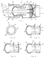
- Fig. 1
- ein Brennerrohr in einer Längsschnittdarstellung als Ausführungsbeispiel der Erfindung,
- Fig. 2
- eine Stirnansicht auf den Fußbereich des pilzartigen Ventilglieds,
- Fig. 3
- ein weiteres Ausführungsbeispiel eines Ventilglieds mit verschlossenem Ende des Fußbereichs,
- Fig. 4
- ein ähnliches Ventilglied wie in Fig. 3 dargestellt, jedoch mit Durchgangsöffnungen in der den Fußbereich abschließenden Platte, und
- Fig. 5
- ein weiteres Ausführungsbeispiel eines Ventilglieds mit verkürzten Längsschlitzen.
Claims (10)
- Brennerrohr für den Brenner einer Heizanlage, das als Strömungsrohr für die Luftströmung eines vorgeschalteten Gebläses ausgebildet ist, mit einem insbesondere konzentrisch im Brennerrohr (10) angeordneten, axial verschiebbaren und mit einer Austrittsdüse (16) versehenen Brennstoff -Zuführungsrohr (17), mit einem im Bereich des Brennerrohr-Ausgangs (14) stromabwärts hinter der Austrittsdüse (16) angeordneten und zusammen mit dieser verschiebbaren Mischelement (15) und mit einer einstellbaren Drosseleinrichtung für die dem Mischbereich zugeführte Luftströmung (13), dadurch gekennzeichnet, daß ein Ventilglied (22; 28; 29; 30) der stromaufwärts vor der Austrittsdüse (16) im Brennerrohr (10) angeordneten Drosseleinrichtung am Brennstoff-Zuführungsrohr (17) angebracht und mit diesem axial verschiebbar ist, wobei das Ventilglied (22; 28; 29; 30) mit einem ringartigen Verengungsbereich (21) des Brennerrohrs (10) zusammenwirkt.
- Brennerrohr nach Anspruch 1, dadurch gekennzeichnet, daß das Ventilglied (22; 28; 29; 30) als pilzartiger Hohlkörper ausgebildet ist, dessen Kopfbereich (23) einen größeren Durchmesser als der Verengungsbereich (21) aufweist, und dessen im wesentlichen zylinderrohrförmiger Fußbereich (24) mit dem Verengungsbereich (21) zusammenwirkende Schlitzöffnungen (25) besitzt.
- Brennerrohr nach Anspruch 2, dadurch gekennzeichnet, daß der Kopfbereich (23) stromaufwärts vor dem Verengungsbereich (21) angeordnet ist.
- Brennerrohr nach Anspruch 2 oder 3, dadurch gekennzeichnet, daß der Kopfbereich (23) zur Umlenkung der Luftströmung (13) im wesentlichen strömungsundurchlässig ist.
- Brennerrohr nach einem der Ansprüche 2 bis 4, dadurch gekennzeichnet, daß die Schlitzöffnungen (25) als über den Umfang verteilte Längsschlitze ausgebildet sind, die sich insbesondere im wesentlichen über die gesamte Länge des Fußbereichs (24) erstrecken oder nur über eine am Kopfbereich (23) ansetzende Teillänge.
- Brennerrohr nach einem der Ansprüche 2 bis 5, dadurch gekennzeichnet, daß der Durchmesser des zylinderrohrförmigen Fußbereichs (24) nahezu dem Durchmesser des Verengungsbereichs (21) entspricht oder kleiner ist.
- Brennerrohr nach einem der vorhergehenden Ansprüche, dadurch gekennzeichnet, daß das vom Kopfbereich (23) abgewandte Ende des Fußbereichs (24) offen oder durch eine Platte (31; 33) abgeschlossen ist, die Durchgangsöffnungen (34) besitzt oder im wesentlichen strömungsundurchlässig ist.
- Brennerrohr nach einem der vorhergehenden Ansprüche, dadurch gekennzeichnet, daß der Verengungsbereich (21) durch eine ringartige Einformung der Wandung des Brennerrohrs (10) oder durch einen ringartigen Einsatz im Inneren des Brennerrohrs (10) gebildet wird.
- Brennerrohr nach einem der vorhergehenden Ansprüche, dadurch gekennzeichnet, daß sein Austritts-Endbereich im Bewegungsbereich des insbesondere als Stauscheibe ausgebildeten Mischelements (15) konusartig zum Ende hin verjüngt ist.
- Brennerrohr nach einem der vorhergehenden Ansprüche, dadurch gekennzeichnet, daß zur axialen Positionierung des Brennstoff-Zuführungsrohrs (17) eine motorische oder manuelle Stelleinrichtung vorgesehen ist.
Priority Applications (3)
| Application Number | Priority Date | Filing Date | Title |
|---|---|---|---|
| EP98118435A EP0990844B1 (de) | 1998-09-29 | 1998-09-29 | Brennerrohr für den Brenner einer Heizanlage |
| AT98118435T ATE227823T1 (de) | 1998-09-29 | 1998-09-29 | Brennerrohr für den brenner einer heizanlage |
| DE59806282T DE59806282D1 (de) | 1998-09-29 | 1998-09-29 | Brennerrohr für den Brenner einer Heizanlage |
Applications Claiming Priority (1)
| Application Number | Priority Date | Filing Date | Title |
|---|---|---|---|
| EP98118435A EP0990844B1 (de) | 1998-09-29 | 1998-09-29 | Brennerrohr für den Brenner einer Heizanlage |
Publications (2)
| Publication Number | Publication Date |
|---|---|
| EP0990844A1 true EP0990844A1 (de) | 2000-04-05 |
| EP0990844B1 EP0990844B1 (de) | 2002-11-13 |
Family
ID=8232713
Family Applications (1)
| Application Number | Title | Priority Date | Filing Date |
|---|---|---|---|
| EP98118435A Expired - Lifetime EP0990844B1 (de) | 1998-09-29 | 1998-09-29 | Brennerrohr für den Brenner einer Heizanlage |
Country Status (3)
| Country | Link |
|---|---|
| EP (1) | EP0990844B1 (de) |
| AT (1) | ATE227823T1 (de) |
| DE (1) | DE59806282D1 (de) |
Cited By (1)
| Publication number | Priority date | Publication date | Assignee | Title |
|---|---|---|---|---|
| US10016384B2 (en) | 2010-06-02 | 2018-07-10 | Diffusion Pharmaceuticals Llc | Oral formulations of bipolar trans carotenoids |
Citations (7)
| Publication number | Priority date | Publication date | Assignee | Title |
|---|---|---|---|---|
| US2553130A (en) * | 1946-06-20 | 1951-05-15 | Cadella Anthony | Air directing means for gun type oil burners |
| FR1316988A (fr) * | 1962-03-07 | 1963-02-01 | Babcock & Wilcox France | Perfectionnements aux appareils de combustion |
| FR1484973A (fr) * | 1966-06-24 | 1967-06-16 | Optimal Olfeuerungsmaschb Gmbh | Procédé pour faire fonctionner un brûleur à pulvérisation de mazout sous pression et brûleur à pulvérisation de mazout sous pression pour la mise en oeuvre de ceprocédé |
| DE1927335A1 (de) * | 1969-05-29 | 1971-02-04 | Koerting Oel Gasfeuerung | Brenner,insbesondere OElbrenner |
| DE4023363A1 (de) | 1990-07-23 | 1992-02-06 | Elco Energiesysteme Gmbh | Brenner |
| EP0588072A1 (de) | 1992-09-15 | 1994-03-23 | Körting Hannover Ag | Gebläsebrenner |
| DE19503781A1 (de) | 1995-02-04 | 1996-08-08 | Buderus Heiztechnik Gmbh | Öl- oder Gasgebläsebrenner |
-
1998
- 1998-09-29 EP EP98118435A patent/EP0990844B1/de not_active Expired - Lifetime
- 1998-09-29 AT AT98118435T patent/ATE227823T1/de not_active IP Right Cessation
- 1998-09-29 DE DE59806282T patent/DE59806282D1/de not_active Expired - Fee Related
Patent Citations (7)
| Publication number | Priority date | Publication date | Assignee | Title |
|---|---|---|---|---|
| US2553130A (en) * | 1946-06-20 | 1951-05-15 | Cadella Anthony | Air directing means for gun type oil burners |
| FR1316988A (fr) * | 1962-03-07 | 1963-02-01 | Babcock & Wilcox France | Perfectionnements aux appareils de combustion |
| FR1484973A (fr) * | 1966-06-24 | 1967-06-16 | Optimal Olfeuerungsmaschb Gmbh | Procédé pour faire fonctionner un brûleur à pulvérisation de mazout sous pression et brûleur à pulvérisation de mazout sous pression pour la mise en oeuvre de ceprocédé |
| DE1927335A1 (de) * | 1969-05-29 | 1971-02-04 | Koerting Oel Gasfeuerung | Brenner,insbesondere OElbrenner |
| DE4023363A1 (de) | 1990-07-23 | 1992-02-06 | Elco Energiesysteme Gmbh | Brenner |
| EP0588072A1 (de) | 1992-09-15 | 1994-03-23 | Körting Hannover Ag | Gebläsebrenner |
| DE19503781A1 (de) | 1995-02-04 | 1996-08-08 | Buderus Heiztechnik Gmbh | Öl- oder Gasgebläsebrenner |
Cited By (1)
| Publication number | Priority date | Publication date | Assignee | Title |
|---|---|---|---|---|
| US10016384B2 (en) | 2010-06-02 | 2018-07-10 | Diffusion Pharmaceuticals Llc | Oral formulations of bipolar trans carotenoids |
Also Published As
| Publication number | Publication date |
|---|---|
| EP0990844B1 (de) | 2002-11-13 |
| DE59806282D1 (de) | 2002-12-19 |
| ATE227823T1 (de) | 2002-11-15 |
Similar Documents
| Publication | Publication Date | Title |
|---|---|---|
| EP0769655B1 (de) | Airblast-Zerstäuberdüse | |
| DE19729047C1 (de) | Mischvorrichtung zur Erzeugung eines Gemisches aus Gas und Verbrennungsluft für einen Brenner | |
| DE4228816C2 (de) | Brenner für Gasturbinentriebwerke | |
| DE69732182T2 (de) | Brennstoff-luft-mischgerät | |
| EP1875061B1 (de) | Abgasrückführeinrichtung | |
| EP0777084B1 (de) | Mischeinrichtung für einen Brenner | |
| EP0692675A2 (de) | Verfahren und Vorrichtung zum Betreiben eines kombinierten Brenners für flüssige und gasförmige Brennstoffe | |
| DE102005032109B4 (de) | Kohlenstaubbrenner für niedrige NOx-Emissionen | |
| DE3850935T2 (de) | Gas/luft-verhältnis-kontrollventil für gasbrenner. | |
| DE4032582C2 (de) | Gasbrenner, insbesondere für Glasschmelzöfen | |
| EP0242579B1 (de) | Vorrichtung zur Regelung der Menge und/oder des Mischungsverhältnisses eines Brenngas-Luft-Gemisches | |
| DE102017120370B4 (de) | Brennerkopf, Brennersystem und Verfahren zum Betreiben des Brennersystems | |
| EP0990844B1 (de) | Brennerrohr für den Brenner einer Heizanlage | |
| EP0508164B1 (de) | Vorrichtung zur Regelung der Menge und/oder des Mischungsverhältnisses eines Brenngas-Luft-Gemisches | |
| EP2024618B1 (de) | Turboverdichter für eine brennkraftmaschine | |
| DE69712452T2 (de) | Brenner mit hoher Wärmeabgabe | |
| EP2287530A2 (de) | Mischeinrichtung für einen Brenner | |
| EP2295857B1 (de) | Brenner mit Mischkopf mit axial verstellbarem Düsenstock | |
| EP2610474B1 (de) | Niederdruck-Abgasrückführventil | |
| WO2003076846A1 (de) | Brenner, insbesondere für flüssige oder gasförmige brennstoffe | |
| DE2125696C3 (de) | Mischdüse für einen Gasbrenner, insbesondere einen Gebläsegas brenner | |
| DE3939508A1 (de) | Vorrichtung zur steuerung der luft- und/oder kraftstoffmenge in verbrennungskraftmaschinen | |
| DE19824719C2 (de) | Brenner, insbesondere Ölbrenner | |
| EP0207478B1 (de) | Vorrichtung zum Verbrennen, insbesondere von reaktionsträgem Kohlenstaub | |
| DE809662C (de) | Industrie-Gasbrenner |
Legal Events
| Date | Code | Title | Description |
|---|---|---|---|
| PUAI | Public reference made under article 153(3) epc to a published international application that has entered the european phase |
Free format text: ORIGINAL CODE: 0009012 |
|
| 17P | Request for examination filed |
Effective date: 19990322 |
|
| AK | Designated contracting states |
Kind code of ref document: A1 Designated state(s): AT CH DE ES FR GB IT LI SE |
|
| AX | Request for extension of the european patent |
Free format text: AL;LT;LV;MK;RO;SI |
|
| AKX | Designation fees paid |
Free format text: AT CH DE ES FR GB IT LI SE |
|
| 17Q | First examination report despatched |
Effective date: 20010621 |
|
| GRAG | Despatch of communication of intention to grant |
Free format text: ORIGINAL CODE: EPIDOS AGRA |
|
| GRAG | Despatch of communication of intention to grant |
Free format text: ORIGINAL CODE: EPIDOS AGRA |
|
| GRAH | Despatch of communication of intention to grant a patent |
Free format text: ORIGINAL CODE: EPIDOS IGRA |
|
| GRAH | Despatch of communication of intention to grant a patent |
Free format text: ORIGINAL CODE: EPIDOS IGRA |
|
| GRAA | (expected) grant |
Free format text: ORIGINAL CODE: 0009210 |
|
| AK | Designated contracting states |
Kind code of ref document: B1 Designated state(s): AT CH DE ES FR GB IT LI SE |
|
| PG25 | Lapsed in a contracting state [announced via postgrant information from national office to epo] |
Ref country code: IT Free format text: LAPSE BECAUSE OF FAILURE TO SUBMIT A TRANSLATION OF THE DESCRIPTION OR TO PAY THE FEE WITHIN THE PRESCRIBED TIME-LIMIT;WARNING: LAPSES OF ITALIAN PATENTS WITH EFFECTIVE DATE BEFORE 2007 MAY HAVE OCCURRED AT ANY TIME BEFORE 2007. THE CORRECT EFFECTIVE DATE MAY BE DIFFERENT FROM THE ONE RECORDED. Effective date: 20021113 Ref country code: GB Free format text: LAPSE BECAUSE OF FAILURE TO SUBMIT A TRANSLATION OF THE DESCRIPTION OR TO PAY THE FEE WITHIN THE PRESCRIBED TIME-LIMIT Effective date: 20021113 Ref country code: FR Free format text: LAPSE BECAUSE OF FAILURE TO SUBMIT A TRANSLATION OF THE DESCRIPTION OR TO PAY THE FEE WITHIN THE PRESCRIBED TIME-LIMIT Effective date: 20021113 |
|
| REF | Corresponds to: |
Ref document number: 227823 Country of ref document: AT Date of ref document: 20021115 Kind code of ref document: T |
|
| REG | Reference to a national code |
Ref country code: GB Ref legal event code: FG4D Free format text: NOT ENGLISH |
|
| REG | Reference to a national code |
Ref country code: CH Ref legal event code: EP |
|
| REF | Corresponds to: |
Ref document number: 59806282 Country of ref document: DE Date of ref document: 20021219 |
|
| PG25 | Lapsed in a contracting state [announced via postgrant information from national office to epo] |
Ref country code: SE Free format text: LAPSE BECAUSE OF FAILURE TO SUBMIT A TRANSLATION OF THE DESCRIPTION OR TO PAY THE FEE WITHIN THE PRESCRIBED TIME-LIMIT Effective date: 20030213 |
|
| GBV | Gb: ep patent (uk) treated as always having been void in accordance with gb section 77(7)/1977 [no translation filed] |
Effective date: 20021113 |
|
| PG25 | Lapsed in a contracting state [announced via postgrant information from national office to epo] |
Ref country code: ES Free format text: LAPSE BECAUSE OF FAILURE TO SUBMIT A TRANSLATION OF THE DESCRIPTION OR TO PAY THE FEE WITHIN THE PRESCRIBED TIME-LIMIT Effective date: 20030529 |
|
| EN | Fr: translation not filed | ||
| PLBE | No opposition filed within time limit |
Free format text: ORIGINAL CODE: 0009261 |
|
| STAA | Information on the status of an ep patent application or granted ep patent |
Free format text: STATUS: NO OPPOSITION FILED WITHIN TIME LIMIT |
|
| PG25 | Lapsed in a contracting state [announced via postgrant information from national office to epo] |
Ref country code: AT Free format text: LAPSE BECAUSE OF NON-PAYMENT OF DUE FEES Effective date: 20030929 |
|
| PG25 | Lapsed in a contracting state [announced via postgrant information from national office to epo] |
Ref country code: LI Free format text: LAPSE BECAUSE OF NON-PAYMENT OF DUE FEES Effective date: 20030930 Ref country code: CH Free format text: LAPSE BECAUSE OF NON-PAYMENT OF DUE FEES Effective date: 20030930 |
|
| 26N | No opposition filed |
Effective date: 20030814 |
|
| REG | Reference to a national code |
Ref country code: CH Ref legal event code: PL |
|
| PGFP | Annual fee paid to national office [announced via postgrant information from national office to epo] |
Ref country code: DE Payment date: 20070921 Year of fee payment: 10 |
|
| PG25 | Lapsed in a contracting state [announced via postgrant information from national office to epo] |
Ref country code: DE Free format text: LAPSE BECAUSE OF NON-PAYMENT OF DUE FEES Effective date: 20090401 |