EP0990884A2 - Verfahren zur Fertigung eines in einem Kraftsensor zur Messung von Kräften eingesetzten Federkörpers sowie ein solcher Federkörper - Google Patents
Verfahren zur Fertigung eines in einem Kraftsensor zur Messung von Kräften eingesetzten Federkörpers sowie ein solcher Federkörper Download PDFInfo
- Publication number
- EP0990884A2 EP0990884A2 EP99119476A EP99119476A EP0990884A2 EP 0990884 A2 EP0990884 A2 EP 0990884A2 EP 99119476 A EP99119476 A EP 99119476A EP 99119476 A EP99119476 A EP 99119476A EP 0990884 A2 EP0990884 A2 EP 0990884A2
- Authority
- EP
- European Patent Office
- Prior art keywords
- spring body
- bores
- force
- receiving bore
- spring
- Prior art date
- Legal status (The legal status is an assumption and is not a legal conclusion. Google has not performed a legal analysis and makes no representation as to the accuracy of the status listed.)
- Granted
Links
- 238000004519 manufacturing process Methods 0.000 title claims abstract description 18
- 238000000034 method Methods 0.000 claims abstract description 18
- 238000005259 measurement Methods 0.000 claims description 9
- 238000005452 bending Methods 0.000 claims description 6
- 230000003628 erosive effect Effects 0.000 claims description 3
- 238000009530 blood pressure measurement Methods 0.000 claims description 2
- 238000001514 detection method Methods 0.000 claims 2
- 238000005553 drilling Methods 0.000 description 2
- 239000007787 solid Substances 0.000 description 2
- 230000000694 effects Effects 0.000 description 1
- 238000005516 engineering process Methods 0.000 description 1
- 239000011888 foil Substances 0.000 description 1
- 239000000463 material Substances 0.000 description 1
- 238000003801 milling Methods 0.000 description 1
- 230000003313 weakening effect Effects 0.000 description 1
Images
Classifications
-
- G—PHYSICS
- G01—MEASURING; TESTING
- G01L—MEASURING FORCE, STRESS, TORQUE, WORK, MECHANICAL POWER, MECHANICAL EFFICIENCY, OR FLUID PRESSURE
- G01L1/00—Measuring force or stress, in general
- G01L1/20—Measuring force or stress, in general by measuring variations in ohmic resistance of solid materials or of electrically-conductive fluids; by making use of electrokinetic cells, i.e. liquid-containing cells wherein an electrical potential is produced or varied upon the application of stress
- G01L1/22—Measuring force or stress, in general by measuring variations in ohmic resistance of solid materials or of electrically-conductive fluids; by making use of electrokinetic cells, i.e. liquid-containing cells wherein an electrical potential is produced or varied upon the application of stress using resistance strain gauges
- G01L1/2206—Special supports with preselected places to mount the resistance strain gauges; Mounting of supports
- G01L1/2231—Special supports with preselected places to mount the resistance strain gauges; Mounting of supports the supports being disc- or ring-shaped, adapted for measuring a force along a single direction
- G01L1/2237—Special supports with preselected places to mount the resistance strain gauges; Mounting of supports the supports being disc- or ring-shaped, adapted for measuring a force along a single direction the direction being perpendicular to the central axis
Definitions
- the invention relates to a method for producing a used in a force sensor to measure forces Spring body.
- the invention further relates to a Spring body of a force sensor for measuring forces, of a receiving hole for receiving a part of a has a stressed element and the is designed in the case of a radial force on the receiving bore on the Spring body a force-proportional surface expansion to have, with strain gauges on the spring body attached to record these surface strains are.
- Force sensors for measuring forces for example, for measuring tape tension everywhere used where running webs like paper webs, Tapes, foils, wires or cables continuously processed or refined. They serve the purpose the tensile forces that occur in the web of material increase directly measure so that the output of the measuring device for a downstream control loop is available.
- Such force sensors usually include one Spring body, which can accommodate a part, of an element exposed to stress.
- the Element can be, for example, a wave be given, the ends of which are mounted in the spring body are, or in a rigid axis, the one internal roller holds.
- the spring body is like this designed that one of the element on the spring body exerted force a surface change of the spring body evokes.
- To record the surface change are strain gauges attached to the spring body, the one the surface change and thus the force Output voltage signal.
- the spring body is also easy to install Usually housed in an outer casing.
- the spring body used is the tensile force measuring device for example by one with three connected columns provided body, the Columns are each completed by drilling and whereby the course of the gap creates a double bending beam leaves.
- a disadvantage of the known manufacturing processes for the Spring body of such force sensors is that for very precise measurements based on the concrete nominal force value spring body designed for the respective application is required. For this reason, for everyone Use case for the manufacture of the spring body, the usually produced by eroding or milling be a new setting of manufacturing machines respectively. The manufacture of the spring body is thereby little flexible and expensive.
- the invention has for its object a flexible and inexpensive method of manufacturing a Spring body of a force sensor for the measurement of To provide forces.
- the Invention based on the task of a flexibly adaptable Spring body of a force sensor for the measurement of To create forces.
- the task is according to a spring body the preamble of claim 10 solved in that the Spring body four, with respect to the location hole axially parallel bores and two elongated ones Columns extending axially parallel through the spring body has, wherein the holes have a diameter according to a desired nominal force value and one gap and two holes in a row are interconnected, and that the strain gauges are placed over the holes.
- the invention is characterized in that initially a Basic body of a spring body in large numbers can be manufactured uniformly. Only then will through the application-specific expansion of the holes fine-tuning to a desired nominal force value carried out. These measures allow one cheaper, more flexible and simplified production.
- the holes and columns in the The spring body is positioned in this way (step a)) and interconnected (step c)) that a Double bending beam results.
- step a) the holes and columns in the The spring body is positioned in this way (step a)) and interconnected (step c)) that a Double bending beam results.
- step a) Another preferred design in terms of production technology is that the columns attached in step a) are two externally accessible columns, each up just before one of the holes reach and the in step c) be extended up to this respective hole.
- Accessibility from the outside can be the manufacturing step c) done particularly easily.
- strain gauges over the four or selected two of those for the Measuring range adjustment expanded or to be expanded Holes are made.
- This positioning of the Strain gauge allows easy Measuring range adjustment by weakening the Spring body, especially the bending beam, on the Back under the strain gauges, because at these points an immediate and widening of the holes influence to be set on the extent of the There is a change in surface when force is applied. Nevertheless, it is also possible in this case that Strain gauges even before the holes are expanded to apply, since those facing away from the strain gauges Sides of the holes are still freely accessible.
- inventive method and the inventive Device are based on a Embodiment with reference to a drawing described in more detail.
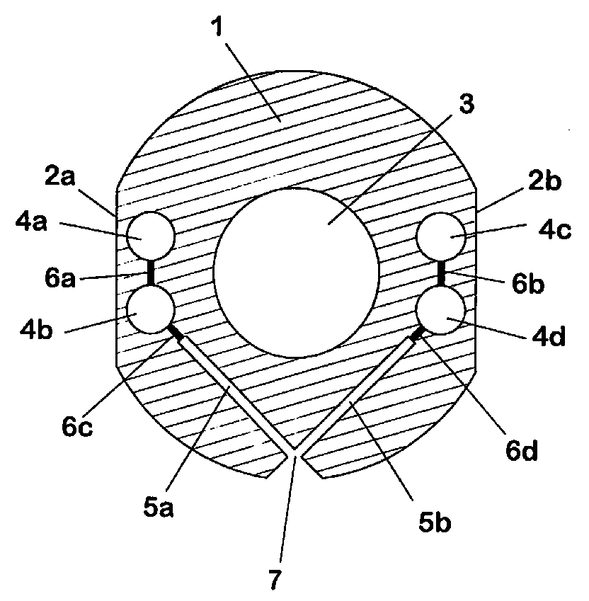
- the spring body 1 is essentially cylindrical with opposite flattened sides 2a, 2b and points a mounting hole 3. Right and left of the Location hole 3 are arranged one above the other two further holes 4a-4d are present, which are axially parallel to the receiving bore 3 through the entire Extend spring body. Furthermore, the same goes two columns 5a, 5b through the entire spring body 1. Each the columns 5a, 5b are with two superimposed Bores 4a / 4b or 4c / 4d connected, which in Connection with the flattened sides 2a, 2b a Double beam arrangement is available.
- the spring body 1 shown is as follows manufactured:
- the solid cylinders are equipped with a central receiving hole 3 provided that the recording an exposed element or one Part of such an element should serve.
- a central receiving hole 3 On both Sides of the mounting hole 3 are two more, Bores 4a, 4b and 4c, 4d arranged closely one above the other appropriate.
- the four holes 4a-4b are designed to the largest measuring range of applications for which the Series is determined.
- the required one The diameter of the holes 4a-4d determined and the previously Uniformly designed holes 4a-4d accordingly expanded. Then the columns 5a, 5b with the each next hole 4b or 4d connected and likewise the holes 4a and 4b lying one above the other or 4c and 4d. Through the columns accessible from the outside 5a, 5b, this is possible in a particularly simple manner and can be done by Sawing or other methods such as eroding take place.
- Double beam creates the spring action of the Spring body 1 results and thus the one to be detected force-proportional change in surface upon action a force by a in the mounting hole 3 used element allows.
- strain gauges are placed over the Drilled holes 4a-4d and the finished spring body 1 mounted in a housing, not shown, and wired.
- the strain gauges can already be used be applied before expanding the holes 4a-4d. In this case, drilling is carried out from the Strain gauge facing away from the holes 4a-4d.
- strain gauges and means for connection to the Outer housings are not shown in the figure.
- a spring body 1 made from a prefabricated part, which as Double bending beam arrangement their typical good Has properties. Beyond that though Manufacture of a basic type in large numbers, the only needs to be fine-tuned, additionally one inexpensive and flexible production with the invention Procedure possible.
Landscapes
- Physics & Mathematics (AREA)
- General Physics & Mathematics (AREA)
- Force Measurement Appropriate To Specific Purposes (AREA)
- Measurement Of Force In General (AREA)
Abstract
Description
das die folgenden Schritte umfaßt:
Claims (13)
- Verfahren zur Fertigung eines in einem Kraftsensor zur Messung von Kräften eingesetzten Federkörpers (1), der eine Aufnahmebohrung (3) zur Aufnahme eines Teils eines einer Belastung ausgesetzten Elementes aufweist und dessen Federwirkung mit dem durch bezüglich der Aufnahmebohrung (3) achsparallele Bohrungen (4a-4d) und Spalten (5a,5b) erzielt wird, wobei an geeigneter Stelle an dem Federkörper (1) Dehnmeßstreifen aufgebracht werden zum Erfassen einer durch die durch das Element ausgeübten Kraft bewirkten Oberflächendehnung und zum Erzeugen einer diese Oberflächendehnung abbildenden Spannung, und wobei mit der Größe der Bohrungen (4a-4d) der gewünschte Nennkraftwert festlegt wird,
das die folgenden Schritte umfaßt:a) Erstellen eines Vorprodukts für den Federkörper (1) mit Aufnahmebohrung (3), sowie durchgehenden Spalten (5a,5b) und Bohrungen (4a-4d), wobei der Durchmesser der Bohrungen (4a-4d) entsprechend dem größten gewünschten Meßbereich für eine Anzahl von Federkörpern (1) gewählt wird,b) Erweitern der Bohrungen (4a-4d) des Federkörpers (1) entsprechend einem gewünschten Nennkraftwert für eine spezielle Applikation, undc) Verbinden von Bohrungen (4a-4d) und Spalten (5a,5b) des Federkörpers (1) durch Auftrennen der sie verbindenden Bereiche (6a-6d) des Federkörpers (1) zur Erzeugung der Federwirkung. - Verfahren nach Anspruch 1,
dadurch gekennzeichnet,
daß die Bohrungen (4a-4d) und Spalten (5a,5b) in dem Federkörper (1) derart positioniert (Schritt a)) und miteinander verbunden (Schritt c)) werden, daß sich ein Doppelbiegebalken ergibt. - Verfahren nach Anspruch 1 oder 2,
dadurch gekennzeichnet,
daß die in Schritt a) angebrachten Spalten (5a,5b) zwei von außen zugängliche Spalten (5a,5b) sind, die jeweils bis kurz vor eine der Bohrungen (4b,4d) reichen und die in Schritt c) bis zu dieser jeweiligen Bohrung (4b,4d) verlängert werden. - Verfahren nach einem der voranstehenden Ansprüche,
dadurch gekennzeichnet,
daß das Verbinden der Bohrungen (4a/4b,4c/4d) untereinander und mit den Spalten (5a,5b) durch Sägen, Erodieren oder einer anderen geeigneten Methoden erfolgt. - Verfahren nach einem der voranstehenden Ansprüche,
dadurch gekennzeichnet,
daß die für die Erfassung der Oberflächenänderungen eingesetzten Dehnmeßstreifen im Anschluß an einen der Schritte a), b) oder c) an dem Federkörper (1) angebracht werden. - Verfahren nach einem der voranstehenden Ansprüche,
dadurch gekennzeichnet,
daß die Dehnmeßstreifen über den vier oder zwei ausgewählten der vier für die Meßbereichsanpassung erweiterten oder zu erweiternden Bohrungen (4a-4d) angebracht werden. - Verfahren nach einem der voranstehenden Ansprüche,
dadurch gekennzeichnet,
daß die für die Erfassung der Oberflächenänderungen eingesetzten Dehnmeßstreifen als Vollbrücke oder als Halbbrücke geschaltet werden. - Verwendung eines Kraftsensors zur Kräftemessung mit einem nach einem Verfahren nach einem der Ansprüche 1-7 gefertigten Federkörper (1) für Bandzugmessungen.
- Verwendung eines Kraftsensors zur Kräftemessung mit einem nach einem Verfahren nach einem der Ansprüche 1-7 gefertigten Federkörper (1) für Andruckmessungen.
- Federkörper (1) eines Kraftsensors zur Messung von Kräften gefertigt entsprechend dem Verfahren nach einem der Ansprüche 1-7.
- Federkörper (1) eines Kraftsensors zur Messung von Kräften, der eine Aufnahmebohrung (3) zur Aufnahme eines Teils eines einer Belastung ausgesetzten Elements aufweist und der ausgelegt ist, bei einer durch das Element ausgeübte, bezüglich der Aufnahmebohrung (3) radialen Kraft auf den Federkörper (1) eine kraftproportionale Oberflächendehnungen aufzuweisen, wobei auf dem Federkörper (1) Dehnmeßstreifen zur Erfassung dieser Oberflächendehnungen angebracht sind,
dadurch gekennzeichnet,
daß der Federkörper (1) vier, bezüglich der Aufnahmebohrung (3) achsparallele Bohrungen (4a-4d) und zwei längliche, sich achsparallel durch den Federkörper (1) erstreckende Spalten (5a,5b) aufweist, wobei die Bohrungen (4a-4d) einen Durchmesser entsprechend einem gewünschten Nennkraftwert aufweisen und jeweils ein Spalt (5a,5b) und zwei Bohrungen (4b/4a,4d/4c) in Folge miteinander verbunden sind, und daß die Dehnmeßstreifen über den Bohrungen (4a-4d) angebracht sind. - Vorrichtung nach Anspruch 11,
dadurch gekennzeichnet,
daß beide Spalten (5a,5b) von einer achsparallelen Linie (7) an der Außenseite des Federkörpers (1) zugänglich sind. - Kraftsensor zum Messen von Kräften, der einen Federkörper (1) nach einem der Ansprüche 11-12 umfaßt.
Applications Claiming Priority (2)
| Application Number | Priority Date | Filing Date | Title |
|---|---|---|---|
| DE19845341 | 1998-10-02 | ||
| DE19845341A DE19845341C2 (de) | 1998-10-02 | 1998-10-02 | Verfahren zur Fertigung eines in einem Kraftsensor zur Messung von Kräften eingesetzten Federkörpers |
Publications (3)
| Publication Number | Publication Date |
|---|---|
| EP0990884A2 true EP0990884A2 (de) | 2000-04-05 |
| EP0990884A3 EP0990884A3 (de) | 2000-08-02 |
| EP0990884B1 EP0990884B1 (de) | 2002-06-19 |
Family
ID=7883135
Family Applications (1)
| Application Number | Title | Priority Date | Filing Date |
|---|---|---|---|
| EP99119476A Expired - Lifetime EP0990884B1 (de) | 1998-10-02 | 1999-09-30 | Verfahren zur Fertigung eines in einem Kraftsensor zur Messung von Kräften eingesetzten Federkörpers sowie ein solcher Federkörper |
Country Status (2)
| Country | Link |
|---|---|
| EP (1) | EP0990884B1 (de) |
| DE (2) | DE19845341C2 (de) |
Cited By (1)
| Publication number | Priority date | Publication date | Assignee | Title |
|---|---|---|---|---|
| CN114018462A (zh) * | 2021-10-22 | 2022-02-08 | 珠海格力电器股份有限公司 | 一种弹性体结构、力传感器及智能设备 |
Family Cites Families (5)
| Publication number | Priority date | Publication date | Assignee | Title |
|---|---|---|---|---|
| DE3336727C2 (de) * | 1983-10-08 | 1985-09-12 | Erhardt & Leimer GmbH, 8900 Augsburg | Vorrichtung zur Linearkraftmessung |
| US4899599A (en) * | 1987-12-07 | 1990-02-13 | Magnetic Power Systems, Inc. | Strain force sensor means |
| DE4108555C2 (de) * | 1991-03-15 | 1997-02-06 | Honigmann Ind Elektronik Gmbh | Kraftmeßeinrichtung zur Messung der Zugkraft eines über eine drehbare Walze geführten bahnförmigen Guts |
| DE9104628U1 (de) * | 1991-04-16 | 1991-06-27 | Honigmann Industrielle Elektronik GmbH, 5600 Wuppertal | Bahnzugkraftmeßeinrichtung |
| DE19511110A1 (de) * | 1995-03-25 | 1996-09-26 | Haehne Elektronische Messgerae | Vorrichtung zur Bandzugmessung |
-
1998
- 1998-10-02 DE DE19845341A patent/DE19845341C2/de not_active Expired - Fee Related
-
1999
- 1999-09-30 EP EP99119476A patent/EP0990884B1/de not_active Expired - Lifetime
- 1999-09-30 DE DE59901784T patent/DE59901784D1/de not_active Expired - Lifetime
Cited By (2)
| Publication number | Priority date | Publication date | Assignee | Title |
|---|---|---|---|---|
| CN114018462A (zh) * | 2021-10-22 | 2022-02-08 | 珠海格力电器股份有限公司 | 一种弹性体结构、力传感器及智能设备 |
| CN114018462B (zh) * | 2021-10-22 | 2022-10-11 | 珠海格力电器股份有限公司 | 一种力传感器及智能设备 |
Also Published As
| Publication number | Publication date |
|---|---|
| EP0990884B1 (de) | 2002-06-19 |
| DE19845341C2 (de) | 2002-04-04 |
| DE59901784D1 (de) | 2002-07-25 |
| EP0990884A3 (de) | 2000-08-02 |
| DE19845341A1 (de) | 2000-04-27 |
Similar Documents
| Publication | Publication Date | Title |
|---|---|---|
| EP1031021B1 (de) | Prüfverfahren zum zerstörungsfreien prüfen eines schweissverbinders, prüfvorrichtung und ultraschallschweissgerät mit einer solchen vorrichtung | |
| EP1640696B1 (de) | Drucksensor | |
| DE69920759T2 (de) | Lastmessung | |
| EP0012867B1 (de) | Piezoelektrischer Dehnungsaufnehmer | |
| DE2232983A1 (de) | Vorrichtung zum messen der spannung einer laufenden materialbahn, eines drahtes oder dergl | |
| DE2038771B2 (de) | Druck -MeBwertwandler | |
| EP3790675B1 (de) | Messrolle zum feststellen einer eigenschaft eines über die messrolle geführten bandförmigen guts | |
| WO2009059754A1 (de) | Kraft-momenten-sensor | |
| DE3336727A1 (de) | Vorrichtung zur linearkraftmessung | |
| WO2016180554A1 (de) | Verfahren zur bestimmung einer in ein bauteil eingebrachten axialen zugkraft | |
| WO2015010684A1 (de) | Stabförmiger kraftaufnehmer mit verbessertem verformungsverhalten | |
| EP3676043A1 (de) | Verfahren zum schweissen von elektrischen leitern mittels ultraschall sowie ultraschallmetallschweissvorrichtung | |
| DE102013012507B4 (de) | Stabförmiger Kraftaufnehmer mit vereinfachtem Abgleich | |
| DE2631698C2 (de) | Kraftmeßwandler | |
| DE68916269T2 (de) | Verfahren und Vorrichtung zum Eichen eines Systems zur nichtdestruktiven Ermittlung der Stärke eines bandförmigen Materials. | |
| DE69510687T2 (de) | Verfahren und vorrichtung zum quantitativen auswerten des festsetzungsgrades in einer dynamoelektrischen maschine | |
| DE3141767A1 (de) | Kraftwandler | |
| DE19845341C2 (de) | Verfahren zur Fertigung eines in einem Kraftsensor zur Messung von Kräften eingesetzten Federkörpers | |
| DE10158600A1 (de) | Vorrichtung zur Kraft und Leistungsmessung an einer Fahrradtretkurbel | |
| EP1923684B1 (de) | Vorrichtung zum Messen einer Zugkraft innerhalb einer Materialbahn oder eines Materialstranges | |
| EP2433110B1 (de) | Verfahren und vorrichtung zur überstandsmessung an lagerschalen | |
| EP3489647B1 (de) | Dehnungssensor | |
| DE2537403C3 (de) | Kraftmeßelement | |
| DE2615069A1 (de) | Vorrichtung zur ueberwachung der walzenausrichtung bei walzwerken | |
| DE102021130441A1 (de) | Messeinrichtung, System aus einem Schraubgerät und der Messeinrichtung und Verfahren zum Betreiben einer Messeinrichtung sowie Befestigungselement |
Legal Events
| Date | Code | Title | Description |
|---|---|---|---|
| PUAI | Public reference made under article 153(3) epc to a published international application that has entered the european phase |
Free format text: ORIGINAL CODE: 0009012 |
|
| AK | Designated contracting states |
Kind code of ref document: A2 Designated state(s): DE FR GB IT SE |
|
| AX | Request for extension of the european patent |
Free format text: AL;LT;LV;MK;RO;SI |
|
| PUAL | Search report despatched |
Free format text: ORIGINAL CODE: 0009013 |
|
| AK | Designated contracting states |
Kind code of ref document: A3 Designated state(s): AT BE CH CY DE DK ES FI FR GB GR IE IT LI LU MC NL PT SE |
|
| AX | Request for extension of the european patent |
Free format text: AL;LT;LV;MK;RO;SI |
|
| 17P | Request for examination filed |
Effective date: 20010112 |
|
| 17Q | First examination report despatched |
Effective date: 20010227 |
|
| AKX | Designation fees paid |
Free format text: DE FR GB IT SE |
|
| GRAG | Despatch of communication of intention to grant |
Free format text: ORIGINAL CODE: EPIDOS AGRA |
|
| GRAG | Despatch of communication of intention to grant |
Free format text: ORIGINAL CODE: EPIDOS AGRA |
|
| GRAG | Despatch of communication of intention to grant |
Free format text: ORIGINAL CODE: EPIDOS AGRA |
|
| GRAH | Despatch of communication of intention to grant a patent |
Free format text: ORIGINAL CODE: EPIDOS IGRA |
|
| RTI1 | Title (correction) |
Free format text: METHOD OF MANUFACTURING A SPRING MEMBER INSERTED IN A FORCE MEASURING DEVICE AND SUCH A SPRING MEMBER |
|
| GRAH | Despatch of communication of intention to grant a patent |
Free format text: ORIGINAL CODE: EPIDOS IGRA |
|
| GRAA | (expected) grant |
Free format text: ORIGINAL CODE: 0009210 |
|
| AK | Designated contracting states |
Kind code of ref document: B1 Designated state(s): DE FR GB IT SE |
|
| PG25 | Lapsed in a contracting state [announced via postgrant information from national office to epo] |
Ref country code: IT Free format text: LAPSE BECAUSE OF FAILURE TO SUBMIT A TRANSLATION OF THE DESCRIPTION OR TO PAY THE FEE WITHIN THE PRESCRIBED TIME-LIMIT;WARNING: LAPSES OF ITALIAN PATENTS WITH EFFECTIVE DATE BEFORE 2007 MAY HAVE OCCURRED AT ANY TIME BEFORE 2007. THE CORRECT EFFECTIVE DATE MAY BE DIFFERENT FROM THE ONE RECORDED. Effective date: 20020619 Ref country code: GB Free format text: LAPSE BECAUSE OF FAILURE TO SUBMIT A TRANSLATION OF THE DESCRIPTION OR TO PAY THE FEE WITHIN THE PRESCRIBED TIME-LIMIT Effective date: 20020619 Ref country code: FR Free format text: LAPSE BECAUSE OF FAILURE TO SUBMIT A TRANSLATION OF THE DESCRIPTION OR TO PAY THE FEE WITHIN THE PRESCRIBED TIME-LIMIT Effective date: 20020619 |
|
| REG | Reference to a national code |
Ref country code: GB Ref legal event code: FG4D Free format text: NOT ENGLISH |
|
| REF | Corresponds to: |
Ref document number: 59901784 Country of ref document: DE Date of ref document: 20020725 |
|
| PG25 | Lapsed in a contracting state [announced via postgrant information from national office to epo] |
Ref country code: SE Free format text: LAPSE BECAUSE OF FAILURE TO SUBMIT A TRANSLATION OF THE DESCRIPTION OR TO PAY THE FEE WITHIN THE PRESCRIBED TIME-LIMIT Effective date: 20020919 |
|
| GBV | Gb: ep patent (uk) treated as always having been void in accordance with gb section 77(7)/1977 [no translation filed] |
Effective date: 20020619 |
|
| EN | Fr: translation not filed | ||
| PLBE | No opposition filed within time limit |
Free format text: ORIGINAL CODE: 0009261 |
|
| STAA | Information on the status of an ep patent application or granted ep patent |
Free format text: STATUS: NO OPPOSITION FILED WITHIN TIME LIMIT |
|
| 26N | No opposition filed |
Effective date: 20030320 |
|
| PGFP | Annual fee paid to national office [announced via postgrant information from national office to epo] |
Ref country code: DE Payment date: 20130918 Year of fee payment: 15 |
|
| REG | Reference to a national code |
Ref country code: DE Ref legal event code: R119 Ref document number: 59901784 Country of ref document: DE |
|
| REG | Reference to a national code |
Ref country code: DE Ref legal event code: R119 Ref document number: 59901784 Country of ref document: DE Effective date: 20150401 |
|
| PG25 | Lapsed in a contracting state [announced via postgrant information from national office to epo] |
Ref country code: DE Free format text: LAPSE BECAUSE OF NON-PAYMENT OF DUE FEES Effective date: 20150401 |