EP0990896B1 - Analysegerät für ein grossflächiges Bild - Google Patents
Analysegerät für ein grossflächiges Bild Download PDFInfo
- Publication number
- EP0990896B1 EP0990896B1 EP99307163A EP99307163A EP0990896B1 EP 0990896 B1 EP0990896 B1 EP 0990896B1 EP 99307163 A EP99307163 A EP 99307163A EP 99307163 A EP99307163 A EP 99307163A EP 0990896 B1 EP0990896 B1 EP 0990896B1
- Authority
- EP
- European Patent Office
- Prior art keywords
- specimen
- image
- light source
- camera
- receiving means
- Prior art date
- Legal status (The legal status is an assumption and is not a legal conclusion. Google has not performed a legal analysis and makes no representation as to the accuracy of the status listed.)
- Expired - Lifetime
Links
- 238000001962 electrophoresis Methods 0.000 claims abstract description 12
- 238000000034 method Methods 0.000 claims description 12
- 230000005284 excitation Effects 0.000 claims description 5
- 239000000499 gel Substances 0.000 description 30
- 230000003287 optical effect Effects 0.000 description 10
- 239000000523 sample Substances 0.000 description 10
- 238000012937 correction Methods 0.000 description 9
- 238000004458 analytical method Methods 0.000 description 7
- 238000005286 illumination Methods 0.000 description 7
- 238000003384 imaging method Methods 0.000 description 6
- 108020004414 DNA Proteins 0.000 description 4
- 239000003550 marker Substances 0.000 description 4
- 230000001419 dependent effect Effects 0.000 description 3
- 238000002372 labelling Methods 0.000 description 3
- 239000011159 matrix material Substances 0.000 description 3
- 108090000623 proteins and genes Proteins 0.000 description 3
- 102000004169 proteins and genes Human genes 0.000 description 3
- 239000000126 substance Substances 0.000 description 3
- 238000010586 diagram Methods 0.000 description 2
- 230000005684 electric field Effects 0.000 description 2
- 239000011521 glass Substances 0.000 description 2
- 229910052709 silver Inorganic materials 0.000 description 2
- 239000004332 silver Substances 0.000 description 2
- SQGYOTSLMSWVJD-UHFFFAOYSA-N silver(1+) nitrate Chemical compound [Ag+].[O-]N(=O)=O SQGYOTSLMSWVJD-UHFFFAOYSA-N 0.000 description 2
- 230000009466 transformation Effects 0.000 description 2
- QFVHZQCOUORWEI-UHFFFAOYSA-N 4-[(4-anilino-5-sulfonaphthalen-1-yl)diazenyl]-5-hydroxynaphthalene-2,7-disulfonic acid Chemical compound C=12C(O)=CC(S(O)(=O)=O)=CC2=CC(S(O)(=O)=O)=CC=1N=NC(C1=CC=CC(=C11)S(O)(=O)=O)=CC=C1NC1=CC=CC=C1 QFVHZQCOUORWEI-UHFFFAOYSA-N 0.000 description 1
- 108010039206 Biotinidase Proteins 0.000 description 1
- 102000053602 DNA Human genes 0.000 description 1
- 108010001336 Horseradish Peroxidase Proteins 0.000 description 1
- OAICVXFJPJFONN-UHFFFAOYSA-N Phosphorus Chemical compound [P] OAICVXFJPJFONN-UHFFFAOYSA-N 0.000 description 1
- 238000003705 background correction Methods 0.000 description 1
- 229960002685 biotin Drugs 0.000 description 1
- 239000011616 biotin Substances 0.000 description 1
- 238000004364 calculation method Methods 0.000 description 1
- 150000001720 carbohydrates Chemical class 0.000 description 1
- 235000014633 carbohydrates Nutrition 0.000 description 1
- 239000007795 chemical reaction product Substances 0.000 description 1
- 238000004587 chromatography analysis Methods 0.000 description 1
- 239000000470 constituent Substances 0.000 description 1
- 238000001816 cooling Methods 0.000 description 1
- 230000003828 downregulation Effects 0.000 description 1
- 238000007876 drug discovery Methods 0.000 description 1
- 239000000839 emulsion Substances 0.000 description 1
- 239000007850 fluorescent dye Substances 0.000 description 1
- 238000001215 fluorescent labelling Methods 0.000 description 1
- 238000001502 gel electrophoresis Methods 0.000 description 1
- 230000001744 histochemical effect Effects 0.000 description 1
- 150000002605 large molecules Chemical class 0.000 description 1
- 239000007788 liquid Substances 0.000 description 1
- 230000004807 localization Effects 0.000 description 1
- 229920002521 macromolecule Polymers 0.000 description 1
- 238000004519 manufacturing process Methods 0.000 description 1
- 239000000463 material Substances 0.000 description 1
- 239000012528 membrane Substances 0.000 description 1
- QSHDDOUJBYECFT-UHFFFAOYSA-N mercury Chemical compound [Hg] QSHDDOUJBYECFT-UHFFFAOYSA-N 0.000 description 1
- 229910052753 mercury Inorganic materials 0.000 description 1
- 239000005445 natural material Substances 0.000 description 1
- 230000037361 pathway Effects 0.000 description 1
- 229920001184 polypeptide Polymers 0.000 description 1
- -1 polypeptides Chemical class 0.000 description 1
- 102000004196 processed proteins & peptides Human genes 0.000 description 1
- 108090000765 processed proteins & peptides Proteins 0.000 description 1
- 238000012545 processing Methods 0.000 description 1
- 230000005855 radiation Effects 0.000 description 1
- 230000002285 radioactive effect Effects 0.000 description 1
- 239000013074 reference sample Substances 0.000 description 1
- 238000009877 rendering Methods 0.000 description 1
- 238000011160 research Methods 0.000 description 1
- 230000000717 retained effect Effects 0.000 description 1
- 238000000926 separation method Methods 0.000 description 1
- 229910001961 silver nitrate Inorganic materials 0.000 description 1
- 150000003384 small molecules Chemical class 0.000 description 1
- 238000004611 spectroscopical analysis Methods 0.000 description 1
- 238000001228 spectrum Methods 0.000 description 1
- 238000010186 staining Methods 0.000 description 1
- 239000000758 substrate Substances 0.000 description 1
- 231100000027 toxicology Toxicity 0.000 description 1
- 238000012546 transfer Methods 0.000 description 1
- 230000003827 upregulation Effects 0.000 description 1
- 229910052724 xenon Inorganic materials 0.000 description 1
- FHNFHKCVQCLJFQ-UHFFFAOYSA-N xenon atom Chemical compound [Xe] FHNFHKCVQCLJFQ-UHFFFAOYSA-N 0.000 description 1
Images


Classifications
-
- G—PHYSICS
- G01—MEASURING; TESTING
- G01N—INVESTIGATING OR ANALYSING MATERIALS BY DETERMINING THEIR CHEMICAL OR PHYSICAL PROPERTIES
- G01N27/00—Investigating or analysing materials by the use of electric, electrochemical, or magnetic means
- G01N27/26—Investigating or analysing materials by the use of electric, electrochemical, or magnetic means by investigating electrochemical variables; by using electrolysis or electrophoresis
- G01N27/416—Systems
- G01N27/447—Systems using electrophoresis
- G01N27/44704—Details; Accessories
- G01N27/44717—Arrangements for investigating the separated zones, e.g. localising zones
- G01N27/44721—Arrangements for investigating the separated zones, e.g. localising zones by optical means
Definitions
- This invention relates to a large area image scanning and analysis apparatus which may be used especially for the high resolution analysis of electrophoresis gels, membrane blots, autoradiographs and other macroscopic imaging applications.
- Electrophoresis is a well known technique for separating molecules of chemical and biological matter by charge and/or mass.
- Electrophoresis is quite simple.
- a clear gel made either of a synthetic or natural material is placed in a gel-running system that allows separate liquid reservoirs to contact the top and bottom of the slab. After samples are loaded in slots at the top of the slab an electric field is applied across the slab. The charge associated with the samples causes the samples to move through the gel at a rate determined by the size and charge of individual molecules in the sample, and also the electric field.
- molecules of a larger size or smaller charge move more slowly than those which are smaller or are more highly charged. Separation is stopped by removal of the voltage and/or by the molecules reaching positions at which frictional or electrical forces balance to prevent further movement.
- the gel is analysed to determine precise positions of separating molecules. This is usually done by staining the gel and evaluating stained bands. A reference sample is often run at the same time as the analysis, so that the position of the stain bands can be compared to the reference.
- WO9521377A DE4011730A and WO9602824A all disclose scanning electrophoresis systems requiring laser light sources.
- the present invention seeks to overcome the problems associated with the prior art. This may make specific use of the ability to label proteins or DNA or other material with stains which may include pre-labelled fluorescent markers as disclosed in US-A-4874492 or EP0214713B1 or it may include other post-electrophoresis labelling fluorescent stains, or other stains which are luminescent or non-fluorescent or non-luminescent, namely stains such as coomassie blue, or silver, or stains which produce dense reaction products such as avidin-biotin or horseradish peroxidase or many others in the literature and commercially available. It may also include autoradiographs of gels or blots or other specimens where labelling employed is a radioactive marker subsequently visualised on film or by some other means such as a radiation-sensitive film or emulsion.
- the invention consists of an apparatus for acquiring high resolution digital images from a large area specimen, such as the result of an electrophoresis of a fluorescent labelled sample in a gel, the apparatus comprising:
- variable wavelength light source may illuminate the specimen from above, below, or the side of the gel with respect to the location of the position of the image obtaining means.
- the image receiving means comprise an X-Y high precision movement stage, the position of which may be controllably varied in X and Y dimensions under microprocessor control, and a CCD camera, the position of the camera being controlled, in use, to direct selectively the image of a portion of the gel to the camera.
- the CCD camera may be cooled or uncooled, cooling being used to reduce the electronic noise of the camera and provide better signal-to-noise images, or improved image contrast, or longer integrating times on the chip for very low light level samples.
- the CCD camera may be capable of providing an analogue output into a frame grabber, or preferably a digital output of 12-16 bits or more.
- the image receiving means may image the gel directly or via a mirror or other optical pathway which may or may not provide a means of magnification or zooming, and may also provide a further manual or automated means of focussing the specimen image onto the camera.
- the image receiving means may also comprise one or more filters for selecting the wavelength of light which passes to the camera.
- the camera may be an analogue or digital CCD camera device and may be of the type disclosed in US-A-4874492 or EP0214713H 1 or US-A-5672881 .
- the light source may also comprise a filter or combination of filters so that the wavelength range of the illuminating light can be narrowed or varied.
- the light source may alternatively use any wavelength selection device, such as a monochromator by way of example.
- the light source may be varied by computer control so that images of the same topographical location of a large specimen may be taken at different wavelengths of light illumination, including excitation and emission wavelengths.
- the image analysing means may be a standard PC or other computer, appropriately configured.
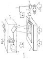
- an apparatus 1 has a stand 2 onto which a gel slab 3 is placed in use.
- a high intensity variable wavelength light source such as a xenon or mercury or white light source available from many manufacturers, is arranged to provide, in use, illuminating light in the direction of either arrows A, B, or C, as will be described below.
- the illuminating light is modulated by the contents of the gel slab 3 upon which an electrophoresis method has been performed.
- the modulated light is then passed to an image receiving means 5 which, in this example, is a mirror 6, filter wheel 7, and cooled CCD camera 8.
- the camera may be an analogue or digital CCD camera device and may be of the type disclosed in US4874492 or EP0214713B1 or US5672881 , which are incorporated herein by reference.
- the position of the CCD camera can be altered by two motors 9 connected to an XY stage, the motors 9 either being controlled by an operator or by an image analysing device coupled to the camera 8.
- the direction of illumination provided by the light source 4 is, in this example, controlled by an optical switch 10 which controls the passage of illuminating light via optical fibres 11 dependent upon the type of specimen being used, and also upon the type of treatment that has been performed on the gel 3.
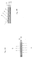
- Figures 2A to 2C show in more detail the direction of illumination that is possible with the present invention.
- the specimen in this example a gel slab 3, is retained within transparent plates 12 during imaging.
- the plates 12 are preferably made from glass.
- illuminating light is passed through the gel slab 3 and onto the image receiving means 5.
- This is often referred to as “transverse illumination”, and the wavelength may be varied by use of variable light sources, or filters, by use of a wavelength converting phosphor-coated plate to produce white light or narrow wavelength excitation light across the sample.
- the illuminating light is transmitted towards the gel slab 3 from the same side of the gel slab 3 as the image receiving means 5, often known as "top illumination” or epi-illumination".
- the light may be delivered from the top in a number of ways. namely by telecentric illumination through the focusing lens on the image receiving means, or through one or two or more light guides offset from the lens and optical axis, or through a dichroic mirror positioned in the optical path.
- the light illuminated gel slab 3 is absorbed by fluorescent molecules in the gel, which emit fluorescent light in the direction of the image receiving means 5.
- a further reflective substrate 13 may be provided to reflect further illuminating light that passes through the gel slab 3 back up towards the image receiving means 5.
- the light source 4 provides illuminating light which is focussed by a cylindrical lens 14 into the gel slab 3, with the glass plates 12 acting as a light guide. This arrangement produces the maximum illuminating efficiency.
- image analysing means is attached, in use, to the output of the camera 8, and can be used to produce output data in many formats, the data being dependent upon the image received.
- gels, blots or other such large area specimens may contain many hundreds or thousands of similar proteins or DNA, and so it is important to acquire images which maintain the highest resolution possible.
- a single or multiple images may be acquired, each providing resolution of at least 50 microns in an X and Y dimension.
- the present invention has also been designed to enable the image receiving means to move mechanically in an X and Y dimension so that this high resolution may be maintained over a very large area. Such movement of the image receiving means may be accomplished at high precision by moving either the specimen or the image receiving means.
- the image receiving means stepwise so that the whole area of the specimen may be imaged.
- Individual images collected may then be reassembled by a software stitching technique embodied in the image analysing means into a single image, while maintaining the full spatial resolution of at least 50 microns. Even higher resolutions may be achievable by different optical configurations, or different lens magnifications.
- a feature of the present invention is the ability to control the scan time and resolution by using standard features of the CCD chip, which allow the acquisition and readout of subarrays of the CCD chip, or binning to provide either faster readout of the CCD chip or greater well-depth of the individual CCD pixels. This can enable higher imaging throughput, albeit at lower overall resolution.
- a further feature of the present invention is the ability to acquire images of more than one fluorescent or luminescent or similar marker, such that several samples may be imaged on a single gel simultaneously or sequentially. This is sometimes called 'sample multiplexing'.
- the two samples may be either an unknown sample and a calibration standard, or two or more unknown samples.
- two or more samples may be labelled with optical probes or markers differentiated by their wavelength spectra. For example, a red-emitting marker and a green-emitting marker may be used to label all the molecular components of two separate samples. Both red- and green- emitting samples are run on a single gel at the same time to give the possibility of precise sample registration and co-localisation of molecular components.
- the present invention provides the capability to acquire simultaneously or sequentially both red- and green- emitting samples by using automated control of excitation or emission wavelength.
- the image acquiring means may then overlay digitally or visually the two samples thus acquired for the purpose of comparing in a quantitative or semi-quantitative sense the amount of each molecular component.
- the image analysing means provides the necessary algorithms to compare the two multiplexed samples to reveal the extent of each molecular component on the specimen with the purpose of measuring up- or down-regulation of a specific molecular component.
- the chemical labelling methodology for running two or more samples on a single gel called sample multiplexing or differential gel electrophoresis is similar to that in US4874492 .
- EP0214713B1 or in WO96/33406 . and is incorporated by reference herein.
- the image analysing means also includes software algorithm to correct potential optical or mechanical distortions and artifacts.
- Lens distortion for example, may be of two types, radial or decentring. Radial distortion affects the position of image points on a straight line radially out from the principal point of the camera. It is also known as a symmetric distortion, since it is a function only of radial distance and is the same at any angle around the principal point. Decentring distortion, often caused by the improper manufacture of the lens, has both a tangential and a radial asymmetric component.
- Tangential distortion occurs in a parallel orientation at each point across the image and varies as a function of the radial distance and the orientation of the line from the point to the principal point with respect to a reference direction.
- the radial asymmetric component is added to the radial component.
- lens decentering distortion x d and y d can also be approximately expressed by a polynomial function.
- x d p 1 ⁇ r 2 + 2 ⁇ x - x O 2 + 2 ⁇ p 2 ⁇ x - x O ⁇ y - y 0
- y d p 2 ⁇ r 2 - 2 ⁇ y - y 0 2 + 2 ⁇ p 1 ⁇ x - x 0 ⁇ y - y 0
- p 1 and P 2 are the parameters of decentering distortion.
- x d and y d are the components of decentering distortion at an image point x,y.
- X lens x r + x d
- Y lens y r + y d
- X lens and Y lens are the total correction for both the radial and decentering distortion correction.
- k1,k2,k3,p1,and p2 is based on a "plumb line" method.
- Two images, with horizontal and vertical lines on it, are acquired in the setup of the present invention.
- the principle is that with no radial and decentring distortion, straight lines in the object space should be straight lines in the image acquired by the image receiving means. Any departures from a straight line can be attributed to lens distortion. These deviations can be used to estimate the distortion parameters k1 - p2 by using a least square estimation of the straight line parameters.
- the k1,k2,k3,p1,and p2 parameters so obtained are held in a standard file which is used to initialise and setup the instrument on every occasion of operation.
- the lens distortion component will be corrected by applying the parameters to the image pixel by pixel.
- a bilinear interpolation algorithm is also applied to smooth the corrected pixel as it is not an integer.
- a further source of imaging error which must be addressed in the image analysing means relates to a mirror or any similar optical transfer element which is interposed between the image receiving means and the specimen.
- this is called mirror distortion correction.
- Mirror distortion is corrected by using a math model of 3rd order polynomial transformation.
- x, y are co-ordinates of dots in the grabbed image plane;
- X,Y are the co-ordinates for ideal location of the dot.
- a 1 - A 10 , B 1 - B 10 are coefficients of the polynomial equations.
- the X and Y are exactly known as they are ideal dots on the grids.
- the x 0 and y 0 can be measured by subpixel location algorithm (see next section) to subpixel accuracy. If we have n (n>10) dots so that we have 2*n equations of above.
- the twenty coefficients of A 1 -A 10 , B1 B 10 can be worked out by least squares fitting.
- a flat plastic paper with 25 (currently being used for imager mirror correction) black dots well distributed in 5x5 ideal grids, is grabbed. Because the positions of the 25 black dots are priorly exactly known(X 1 ,Y 1 ,...X 25 ,Y 25 ). They are used as control points to correct the 25 dots on the grabbed image(x 1 , y 1 ,... x 25 , y 25 ).
- the coefficients (20 in total) of the 3rd order polynomial equation can then be worked out by means of iterative least squares estimation. These parameters are stored in the imager initialisation file. When an image is grabbed, the 3rd order polynomial transformation is applied to the image to correct the mirror distortion. A bilinear interpolation is used to interpolate the corrected pixels into integer array.
- the image analysing means of the present invention it may also be helpful to invoke automatic subpixel localisation to improve image processing and analysing capability at high resolution.
- automatic subpixel location algorithm may thus be needed to improve resolution of small elements in the image.
- One example of an algorithm which may be used in the present invention is called "weighted centroid subpixel location" algorithm.
- a small rectangular window around the dot (or line) is placed such that it covers the whole dot or interested line segment.
- a suitable threshold is used to eliminate background information from the window.
- the choice of a suitable window size can be dependent on the actual dot size or the interested line segment. Using the intensity values within this window the precise centre of the dot or line can be calculated using the following equations.
- w ij is the grey scale value of each pixel and n, m define the window size.
- the algorithm is called weighted centroid subpixel location algorithm.
- This algorithm can locate a line position up to 1/50 of a pixel automatically. This algorithm may be particularly useful in obtaining an accurate line profile of an image, or in resolving small subpixel features in the image. When the profile graph cross a line is displayed, the accurate subpixel centroid of the line may be automatically displayed on the top of the profile graph. This function can also be used to verify the accuracy of correction of image stitching, the geometric accuracy of images and other related features.
- the present invention may also embody standard shading correction and flat fielding correction across the entire image in order to diminish any optical nonuniformities in any part of the light path. This may be achieved by acquiring a blank image of the field without the specimen present, then applying this to specimen images for the purpose of making uniform light across the entire image.
- FIG 3 shows an output 4A flourescent end label DNA sample. It can be seen that the arrangement of the present invention provides a good, accurate and quantitative indication of relative intensities, something that cannot be achieved by manual analysis.
- the light source 4 of the apparatus 1 of the invention has a variable wavelength.
- the apparatus can be employed to analyse the images associated with gel slabs 3 formed from a wide variety of electrophoresis techniques simply by changing the output wavelength of the light source 4 4.
- fluorescent labelling techniques are employed to produce the gel being analysed.
Landscapes
- Health & Medical Sciences (AREA)
- Life Sciences & Earth Sciences (AREA)
- Molecular Biology (AREA)
- Chemical & Material Sciences (AREA)
- Chemical Kinetics & Catalysis (AREA)
- Electrochemistry (AREA)
- Physics & Mathematics (AREA)
- Analytical Chemistry (AREA)
- Biochemistry (AREA)
- General Health & Medical Sciences (AREA)
- General Physics & Mathematics (AREA)
- Immunology (AREA)
- Pathology (AREA)
- Investigating, Analyzing Materials By Fluorescence Or Luminescence (AREA)
- Image Processing (AREA)
- Image Analysis (AREA)
Claims (11)
- Gerät (1) zum Erfassen hochauflösender digitaler Bilder aus einem großflächigen Spezimen, wie beispielsweise dem Ergebnis einer Elektrophorese einer fluoreszierend etikettierten Probe in einem Gel (3), wobei das Gerät umfasst:eine Lichtquelle (4) zum Bereitstellen illuminierenden Lichts für das Spezimen;Bildempfangsmittel (5) zum Erlangen eines hochauflösenden Bilds des illuminierten Spezimens; undBildanalysemittel zum Analysieren des erlangten Bilds, um die Position von Proben auf dem Spezimen zu bestimmen und darauf beruhende Daten bereitzustellen;dadurch gekennzeichnet, dass die Lichtquelle eine Lichtquelle variabler Wellenlänge ist, die über einen kontinuierlichen Bereich von Wellenlängen variabel ist,wobei die Position des Bildempfangsmittels relativ zum Spezimen schrittweise in X- und Y-Dimensionen durch ein X-Y-Bewegungsgestell hoher Präzision variiert (9) wird, um Bilder einer Vielheit von Teilen des Spezimens selektiv zu erlangen und,wobei das Bildanalysemittel die Vielheit selektiv erlangter Bilder von Teilen des Spezimens zu einem Einzelbild zusammensetzt.
- Gerät nach Anspruch 1, wobei die Lichtquelle (4) das Spezimen von oben (b) illuminiert.
- Gerät nach Anspruch 1, wobei die Lichtquelle (4) das Spezimen von unten (a) illuminiert.
- Gerät nach Anspruch 1, wobei die Lichtquelle (4) das Spezimen von der Seite des Spezimens (c) illuminiert.
- Gerät nach Anspruch 1, wobei das Bildempfangsmittel (5) einen Spiegel (6) und eine Kamera (8) umfasst, wobei die Position des Spiegels und der Kamera, in Gebrauch, gesteuert (9) wird, um das Bild eines Teils des Spezimens (3) selektiv zur Kamera zu lenken.
- Gerät nach Anspruch 5, wobei das Bildempfangsmittel (5) außerdem einen Filter (7) zum Selektieren der Wellenlänge des Lichts umfasst, das zur Kamera (8) geleitet wird.
- Gerät nach Anspruch 5, bei dem die Kamera (8) eine CCD-Vorrichtung ist.
- Gerät nach Anspruch 1, wobei das Bildanalysemittel ein angemessen konfigurierter standardmäßiger PC ist.
- Gerät nach Anspruch 1, wobei das Bildempfangsmittel (5) schrittweise relativ zum Spezimen (3) in X- und Y-Richtungen so bewegt wird, dass die Vielheit von selektiv erlangten Bildern die ganze Fläche des Spezimens abdeckt.
- Gerät wie in Anspruch 1 oder Anspruch 9 beansprucht, wobei die Vielheit von selektiv erlangten Bildern vom Bildanalysemittel durch ein Software-Stitching-Verfahren zu einem Einzelbild neu zusammengesetzt werden.
- Gerät nach Anspruch 1, wobei das Bildempfangsmittel (5) einen Spiegel (6), eine Kamera (8), einen Anregungsfilter zum Selektieren der Wellenlänge von Licht aus der Lichtquelle (4), welches das Spezimen illuminiert und einen Emissionsfilter (7) zum Selektieren der Wellenlänge von Licht umfasst, welches zur Kamera (8) geleitet wird, wobei der Anregungsfilter und der Emissionsfilter automatisch gesteuert werden, sodass Bilder jedes Teils des Spezimens, entweder simultan oder sequenziell mit verschiedenen Wellenlängen erlangt werden.
Applications Claiming Priority (2)
| Application Number | Priority Date | Filing Date | Title |
|---|---|---|---|
| US9971898P | 1998-09-10 | 1998-09-10 | |
| US99718 | 1998-09-10 |
Publications (3)
| Publication Number | Publication Date |
|---|---|
| EP0990896A2 EP0990896A2 (de) | 2000-04-05 |
| EP0990896A3 EP0990896A3 (de) | 2000-05-31 |
| EP0990896B1 true EP0990896B1 (de) | 2012-01-25 |
Family
ID=22276301
Family Applications (1)
| Application Number | Title | Priority Date | Filing Date |
|---|---|---|---|
| EP99307163A Expired - Lifetime EP0990896B1 (de) | 1998-09-10 | 1999-09-09 | Analysegerät für ein grossflächiges Bild |
Country Status (3)
| Country | Link |
|---|---|
| EP (1) | EP0990896B1 (de) |
| JP (1) | JP2000111523A (de) |
| AT (1) | ATE543093T1 (de) |
Cited By (3)
| Publication number | Priority date | Publication date | Assignee | Title |
|---|---|---|---|---|
| DE102009030465A1 (de) * | 2009-06-23 | 2011-01-05 | Carl Zeiss Meditec Ag | Fixationskontrolleinrichtung und Verfahren zur Kontrolle einer Fixation eines Auges |
| US8233735B2 (en) | 1994-02-10 | 2012-07-31 | Affymetrix, Inc. | Methods and apparatus for detection of fluorescently labeled materials |
| US8351026B2 (en) | 2005-04-22 | 2013-01-08 | Affymetrix, Inc. | Methods and devices for reading microarrays |
Families Citing this family (10)
| Publication number | Priority date | Publication date | Assignee | Title |
|---|---|---|---|---|
| US20030039383A1 (en) * | 2001-06-26 | 2003-02-27 | Bio-Rad Laboratories, Inc. | Flat field correction of two-dimensional biochemical assay images |
| JP2004003989A (ja) * | 2002-03-15 | 2004-01-08 | Affymetrix Inc | 生物学的物質の走査のためのシステム、方法、および製品 |
| US7317415B2 (en) | 2003-08-08 | 2008-01-08 | Affymetrix, Inc. | System, method, and product for scanning of biological materials employing dual analog integrators |
| US20050221351A1 (en) * | 2004-04-06 | 2005-10-06 | Affymetrix, Inc. | Methods and devices for microarray image analysis |
| JP4619198B2 (ja) * | 2005-05-27 | 2011-01-26 | パナソニック株式会社 | 電気泳動システム |
| JP4970118B2 (ja) * | 2007-04-10 | 2012-07-04 | 日本電信電話株式会社 | カメラ校正方法、そのプログラム、記録媒体、装置 |
| US9767342B2 (en) | 2009-05-22 | 2017-09-19 | Affymetrix, Inc. | Methods and devices for reading microarrays |
| CN111862051B (zh) * | 2020-02-04 | 2021-06-01 | 牧今科技 | 执行自动相机校准的方法和系统 |
| DE102020118790A1 (de) | 2020-02-04 | 2021-08-05 | Mujin, Inc. | Verfahren und system zum durchführen einer automatischen kamerakalibrierung |
| US11508088B2 (en) | 2020-02-04 | 2022-11-22 | Mujin, Inc. | Method and system for performing automatic camera calibration |
Family Cites Families (6)
| Publication number | Priority date | Publication date | Assignee | Title |
|---|---|---|---|---|
| GB8513538D0 (en) * | 1985-05-29 | 1985-07-03 | Mackay C D | Electrophoresis |
| US5062942A (en) * | 1989-04-12 | 1991-11-05 | Hitachi, Ltd. | Fluorescence detection type electrophoresis apparatus |
| CA2058346C (en) * | 1991-01-16 | 1999-03-30 | Robert J. Sarrine | Automatic electrophoresis apparatus and method |
| US5543026A (en) * | 1994-02-07 | 1996-08-06 | The Perkin-Elmer Corporation | Real-time scanning fluorescence electrophoresis apparatus for the analysis of polynucleotide fragments |
| US5459325A (en) * | 1994-07-19 | 1995-10-17 | Molecular Dynamics, Inc. | High-speed fluorescence scanner |
| DE69627183T2 (de) * | 1995-11-30 | 2004-01-29 | Chromavision Med Sys Inc | Verfahren zur automatischen bildanalyse biologischer proben |
-
1999
- 1999-09-09 AT AT99307163T patent/ATE543093T1/de active
- 1999-09-09 EP EP99307163A patent/EP0990896B1/de not_active Expired - Lifetime
- 1999-09-10 JP JP11257184A patent/JP2000111523A/ja not_active Withdrawn
Cited By (3)
| Publication number | Priority date | Publication date | Assignee | Title |
|---|---|---|---|---|
| US8233735B2 (en) | 1994-02-10 | 2012-07-31 | Affymetrix, Inc. | Methods and apparatus for detection of fluorescently labeled materials |
| US8351026B2 (en) | 2005-04-22 | 2013-01-08 | Affymetrix, Inc. | Methods and devices for reading microarrays |
| DE102009030465A1 (de) * | 2009-06-23 | 2011-01-05 | Carl Zeiss Meditec Ag | Fixationskontrolleinrichtung und Verfahren zur Kontrolle einer Fixation eines Auges |
Also Published As
| Publication number | Publication date |
|---|---|
| EP0990896A2 (de) | 2000-04-05 |
| JP2000111523A (ja) | 2000-04-21 |
| EP0990896A3 (de) | 2000-05-31 |
| ATE543093T1 (de) | 2012-02-15 |
Similar Documents
| Publication | Publication Date | Title |
|---|---|---|
| US7199357B1 (en) | Image enhancement by sub-pixel imaging | |
| EP0990896B1 (de) | Analysegerät für ein grossflächiges Bild | |
| US7323681B1 (en) | Image enhancement by sub-pixel imaging | |
| US7027932B2 (en) | Biochemical examination method | |
| US6084991A (en) | CCD imager for confocal scanning microscopy | |
| EP1264167B1 (de) | Vorrichtung und verfahren zum nachweis organischer moleküle in einer probensubstanz | |
| US7283253B2 (en) | Multi-axis integration system and method | |
| JP5174035B2 (ja) | 二次元配列画像化 | |
| Hanley et al. | Spectral imaging in a programmable array microscope by Hadamard transform fluorescence spectroscopy | |
| EP2309253A2 (de) | Vorrichtung zum Lesen von durch resonanzlichtgestreute Partikelmarkierungen erzeugten Signalen | |
| WO2003014400A1 (en) | Time-delay integration imaging of biological specimens | |
| EP3762758B1 (de) | Bildgebungsvorrichtungen, -systeme und -verfahren | |
| CN112236705A (zh) | 借助于光场相机对医学样本进行三维分析的分析仪 | |
| US20030133009A1 (en) | System and method for detecting with high resolution a large, high content field | |
| CN114419114A (zh) | 用于数字病理学色彩校准的系统和方法 | |
| CA2531563A1 (en) | Analysing biological entities | |
| Spibey et al. | A unique charge‐coupled device/xenon arc lamp based imaging system for the accurate detection and quantitation of multicolour fluorescence | |
| US5799773A (en) | Method and apparatus for correcting lens and detector non-uniformities | |
| US6535624B1 (en) | Gel electrophoresis image combining for improved dynamic range | |
| JP2004108892A (ja) | 蛍光分光分析装置 | |
| WO1996037797A1 (en) | Wide field of view microscope and scanning system useful in the microscope | |
| EP1472913B1 (de) | Analyseverfahren | |
| JP2001518197A (ja) | キャピラリィ電気泳動用の装置及び方法 | |
| Ramm | Advanced image analysis systems in cell, molecular and neurobiology applications | |
| Guanquan et al. | Instrument for Hadamard transform three-dimensional fluorescence microscope image analysis |
Legal Events
| Date | Code | Title | Description |
|---|---|---|---|
| PUAI | Public reference made under article 153(3) epc to a published international application that has entered the european phase |
Free format text: ORIGINAL CODE: 0009012 |
|
| AK | Designated contracting states |
Kind code of ref document: A2 Designated state(s): AT BE CH CY DE DK ES FI FR GB GR IE IT LI LU MC NL PT SE |
|
| AX | Request for extension of the european patent |
Free format text: AL;LT;LV;MK;RO;SI |
|
| PUAL | Search report despatched |
Free format text: ORIGINAL CODE: 0009013 |
|
| AK | Designated contracting states |
Kind code of ref document: A3 Designated state(s): AT BE CH CY DE DK ES FI FR GB GR IE IT LI LU MC NL PT SE |
|
| AX | Request for extension of the european patent |
Free format text: AL;LT;LV;MK;RO;SI |
|
| RTI1 | Title (correction) |
Free format text: LARGE AREA IMAGE ANALYSING APPARATUS |
|
| 17P | Request for examination filed |
Effective date: 20001116 |
|
| AKX | Designation fees paid |
Free format text: BE DE DK ES |
|
| RBV | Designated contracting states (corrected) |
Designated state(s): AT BE CH CY DE DK ES FI FR GB GR IE IT LI LU MC NL PT SE |
|
| 17Q | First examination report despatched |
Effective date: 20070214 |
|
| GRAP | Despatch of communication of intention to grant a patent |
Free format text: ORIGINAL CODE: EPIDOSNIGR1 |
|
| GRAS | Grant fee paid |
Free format text: ORIGINAL CODE: EPIDOSNIGR3 |
|
| GRAA | (expected) grant |
Free format text: ORIGINAL CODE: 0009210 |
|
| AK | Designated contracting states |
Kind code of ref document: B1 Designated state(s): AT BE CH CY DE DK ES FI FR GB GR IE IT LI LU MC NL PT SE |
|
| REG | Reference to a national code |
Ref country code: GB Ref legal event code: FG4D |
|
| REG | Reference to a national code |
Ref country code: CH Ref legal event code: EP |
|
| REG | Reference to a national code |
Ref country code: AT Ref legal event code: REF Ref document number: 543093 Country of ref document: AT Kind code of ref document: T Effective date: 20120215 |
|
| REG | Reference to a national code |
Ref country code: IE Ref legal event code: FG4D |
|
| REG | Reference to a national code |
Ref country code: DE Ref legal event code: R096 Ref document number: 69944003 Country of ref document: DE Effective date: 20120322 |
|
| REG | Reference to a national code |
Ref country code: NL Ref legal event code: VDEP Effective date: 20120125 |
|
| PG25 | Lapsed in a contracting state [announced via postgrant information from national office to epo] |
Ref country code: BE Free format text: LAPSE BECAUSE OF FAILURE TO SUBMIT A TRANSLATION OF THE DESCRIPTION OR TO PAY THE FEE WITHIN THE PRESCRIBED TIME-LIMIT Effective date: 20120125 Ref country code: NL Free format text: LAPSE BECAUSE OF FAILURE TO SUBMIT A TRANSLATION OF THE DESCRIPTION OR TO PAY THE FEE WITHIN THE PRESCRIBED TIME-LIMIT Effective date: 20120125 |
|
| PG25 | Lapsed in a contracting state [announced via postgrant information from national office to epo] |
Ref country code: PT Free format text: LAPSE BECAUSE OF FAILURE TO SUBMIT A TRANSLATION OF THE DESCRIPTION OR TO PAY THE FEE WITHIN THE PRESCRIBED TIME-LIMIT Effective date: 20120525 Ref country code: GR Free format text: LAPSE BECAUSE OF FAILURE TO SUBMIT A TRANSLATION OF THE DESCRIPTION OR TO PAY THE FEE WITHIN THE PRESCRIBED TIME-LIMIT Effective date: 20120426 Ref country code: FI Free format text: LAPSE BECAUSE OF FAILURE TO SUBMIT A TRANSLATION OF THE DESCRIPTION OR TO PAY THE FEE WITHIN THE PRESCRIBED TIME-LIMIT Effective date: 20120125 |
|
| REG | Reference to a national code |
Ref country code: AT Ref legal event code: MK05 Ref document number: 543093 Country of ref document: AT Kind code of ref document: T Effective date: 20120125 |
|
| PG25 | Lapsed in a contracting state [announced via postgrant information from national office to epo] |
Ref country code: CY Free format text: LAPSE BECAUSE OF FAILURE TO SUBMIT A TRANSLATION OF THE DESCRIPTION OR TO PAY THE FEE WITHIN THE PRESCRIBED TIME-LIMIT Effective date: 20120125 |
|
| PG25 | Lapsed in a contracting state [announced via postgrant information from national office to epo] |
Ref country code: DK Free format text: LAPSE BECAUSE OF FAILURE TO SUBMIT A TRANSLATION OF THE DESCRIPTION OR TO PAY THE FEE WITHIN THE PRESCRIBED TIME-LIMIT Effective date: 20120125 Ref country code: SE Free format text: LAPSE BECAUSE OF FAILURE TO SUBMIT A TRANSLATION OF THE DESCRIPTION OR TO PAY THE FEE WITHIN THE PRESCRIBED TIME-LIMIT Effective date: 20120125 |
|
| PG25 | Lapsed in a contracting state [announced via postgrant information from national office to epo] |
Ref country code: IT Free format text: LAPSE BECAUSE OF FAILURE TO SUBMIT A TRANSLATION OF THE DESCRIPTION OR TO PAY THE FEE WITHIN THE PRESCRIBED TIME-LIMIT Effective date: 20120125 |
|
| PLBE | No opposition filed within time limit |
Free format text: ORIGINAL CODE: 0009261 |
|
| STAA | Information on the status of an ep patent application or granted ep patent |
Free format text: STATUS: NO OPPOSITION FILED WITHIN TIME LIMIT |
|
| 26N | No opposition filed |
Effective date: 20121026 |
|
| PG25 | Lapsed in a contracting state [announced via postgrant information from national office to epo] |
Ref country code: AT Free format text: LAPSE BECAUSE OF FAILURE TO SUBMIT A TRANSLATION OF THE DESCRIPTION OR TO PAY THE FEE WITHIN THE PRESCRIBED TIME-LIMIT Effective date: 20120125 |
|
| REG | Reference to a national code |
Ref country code: DE Ref legal event code: R097 Ref document number: 69944003 Country of ref document: DE Effective date: 20121026 |
|
| PG25 | Lapsed in a contracting state [announced via postgrant information from national office to epo] |
Ref country code: ES Free format text: LAPSE BECAUSE OF FAILURE TO SUBMIT A TRANSLATION OF THE DESCRIPTION OR TO PAY THE FEE WITHIN THE PRESCRIBED TIME-LIMIT Effective date: 20120506 Ref country code: MC Free format text: LAPSE BECAUSE OF NON-PAYMENT OF DUE FEES Effective date: 20120930 |
|
| REG | Reference to a national code |
Ref country code: CH Ref legal event code: PL |
|
| REG | Reference to a national code |
Ref country code: IE Ref legal event code: MM4A |
|
| REG | Reference to a national code |
Ref country code: FR Ref legal event code: ST Effective date: 20130531 |
|
| PG25 | Lapsed in a contracting state [announced via postgrant information from national office to epo] |
Ref country code: CH Free format text: LAPSE BECAUSE OF NON-PAYMENT OF DUE FEES Effective date: 20120930 Ref country code: LI Free format text: LAPSE BECAUSE OF NON-PAYMENT OF DUE FEES Effective date: 20120930 Ref country code: IE Free format text: LAPSE BECAUSE OF NON-PAYMENT OF DUE FEES Effective date: 20120909 |
|
| PG25 | Lapsed in a contracting state [announced via postgrant information from national office to epo] |
Ref country code: FR Free format text: LAPSE BECAUSE OF NON-PAYMENT OF DUE FEES Effective date: 20121001 |
|
| PG25 | Lapsed in a contracting state [announced via postgrant information from national office to epo] |
Ref country code: LU Free format text: LAPSE BECAUSE OF NON-PAYMENT OF DUE FEES Effective date: 20120909 |
|
| PGFP | Annual fee paid to national office [announced via postgrant information from national office to epo] |
Ref country code: GB Payment date: 20170927 Year of fee payment: 19 |
|
| PGFP | Annual fee paid to national office [announced via postgrant information from national office to epo] |
Ref country code: DE Payment date: 20170927 Year of fee payment: 19 |
|
| REG | Reference to a national code |
Ref country code: DE Ref legal event code: R119 Ref document number: 69944003 Country of ref document: DE |
|
| GBPC | Gb: european patent ceased through non-payment of renewal fee |
Effective date: 20180909 |
|
| PG25 | Lapsed in a contracting state [announced via postgrant information from national office to epo] |
Ref country code: DE Free format text: LAPSE BECAUSE OF NON-PAYMENT OF DUE FEES Effective date: 20190402 |
|
| PG25 | Lapsed in a contracting state [announced via postgrant information from national office to epo] |
Ref country code: GB Free format text: LAPSE BECAUSE OF NON-PAYMENT OF DUE FEES Effective date: 20180909 |