EP0990906B1 - Dispositif de transport de composants dans un système d'analyses automatisé - Google Patents
Dispositif de transport de composants dans un système d'analyses automatisé Download PDFInfo
- Publication number
- EP0990906B1 EP0990906B1 EP98810974A EP98810974A EP0990906B1 EP 0990906 B1 EP0990906 B1 EP 0990906B1 EP 98810974 A EP98810974 A EP 98810974A EP 98810974 A EP98810974 A EP 98810974A EP 0990906 B1 EP0990906 B1 EP 0990906B1
- Authority
- EP
- European Patent Office
- Prior art keywords
- component carrier
- housing
- tray
- transport
- loading bay
- Prior art date
- Legal status (The legal status is an assumption and is not a legal conclusion. Google has not performed a legal analysis and makes no representation as to the accuracy of the status listed.)
- Expired - Lifetime
Links
Images







Classifications
-
- G—PHYSICS
- G01—MEASURING; TESTING
- G01N—INVESTIGATING OR ANALYSING MATERIALS BY DETERMINING THEIR CHEMICAL OR PHYSICAL PROPERTIES
- G01N35/00—Automatic analysis not limited to methods or materials provided for in any single one of groups G01N1/00 - G01N33/00; Handling materials therefor
- G01N35/02—Automatic analysis not limited to methods or materials provided for in any single one of groups G01N1/00 - G01N33/00; Handling materials therefor using a plurality of sample containers moved by a conveyor system past one or more treatment or analysis stations
- G01N35/04—Details of the conveyor system
-
- G—PHYSICS
- G01—MEASURING; TESTING
- G01N—INVESTIGATING OR ANALYSING MATERIALS BY DETERMINING THEIR CHEMICAL OR PHYSICAL PROPERTIES
- G01N35/00—Automatic analysis not limited to methods or materials provided for in any single one of groups G01N1/00 - G01N33/00; Handling materials therefor
- G01N2035/00178—Special arrangements of analysers
- G01N2035/00326—Analysers with modular structure
-
- G—PHYSICS
- G01—MEASURING; TESTING
- G01N—INVESTIGATING OR ANALYSING MATERIALS BY DETERMINING THEIR CHEMICAL OR PHYSICAL PROPERTIES
- G01N35/00—Automatic analysis not limited to methods or materials provided for in any single one of groups G01N1/00 - G01N33/00; Handling materials therefor
- G01N35/02—Automatic analysis not limited to methods or materials provided for in any single one of groups G01N1/00 - G01N33/00; Handling materials therefor using a plurality of sample containers moved by a conveyor system past one or more treatment or analysis stations
- G01N35/04—Details of the conveyor system
- G01N2035/046—General conveyor features
- G01N2035/0465—Loading or unloading the conveyor
-
- Y—GENERAL TAGGING OF NEW TECHNOLOGICAL DEVELOPMENTS; GENERAL TAGGING OF CROSS-SECTIONAL TECHNOLOGIES SPANNING OVER SEVERAL SECTIONS OF THE IPC; TECHNICAL SUBJECTS COVERED BY FORMER USPC CROSS-REFERENCE ART COLLECTIONS [XRACs] AND DIGESTS
- Y10—TECHNICAL SUBJECTS COVERED BY FORMER USPC
- Y10T—TECHNICAL SUBJECTS COVERED BY FORMER US CLASSIFICATION
- Y10T436/00—Chemistry: analytical and immunological testing
- Y10T436/11—Automated chemical analysis
-
- Y—GENERAL TAGGING OF NEW TECHNOLOGICAL DEVELOPMENTS; GENERAL TAGGING OF CROSS-SECTIONAL TECHNOLOGIES SPANNING OVER SEVERAL SECTIONS OF THE IPC; TECHNICAL SUBJECTS COVERED BY FORMER USPC CROSS-REFERENCE ART COLLECTIONS [XRACs] AND DIGESTS
- Y10—TECHNICAL SUBJECTS COVERED BY FORMER USPC
- Y10T—TECHNICAL SUBJECTS COVERED BY FORMER US CLASSIFICATION
- Y10T436/00—Chemistry: analytical and immunological testing
- Y10T436/11—Automated chemical analysis
- Y10T436/113332—Automated chemical analysis with conveyance of sample along a test line in a container or rack
Definitions
- the invention relates to an apparatus for transporting components within an automatic analyzer system.
- the invention relates in particular to an apparatus for transporting components within an automatic analyzer system for analyzing biological samples, which system comprises at least two apparatuses which form part of that system, wherein at least one of said apparatuses includes means for automatically analyzing said biological samples.
- the equipment used by the laboratories often comprises a plurality of specialized analyzers of various types and additionally supplementary equipment like the one for performing preliminary operations such as preparation of biological samples before they are introduced into specialized analyzers.
- supplementary equipment like the one for performing preliminary operations such as preparation of biological samples before they are introduced into specialized analyzers.
- such equipment has to be available in a great diversity of configurations, and it should be possible to modify an initial configuration and to supplement it with additional equipment if and when necessary.
- system components e.g. sample tubes, reagent containers, disposable pipetting tips, etc., from one of the apparatuses forming part of the analyzer system to at least another one of the apparatuses forming part of the analyzer system.
- WO 98 0 1760 (Beckman Instruments) describes analyzer systems with transport means according to the preamble of claim 1.
- Transport means like robot arms and grippers known in the prior art for transporting components in analyzer systems have two major disadvantages. On the one hand, they are relatively expensive, because they require high cost components like sensors and complex control means. On the other hand, known transport systems require a very accurate mechanical adjustments and installation work in order to operate successfully.
- An aim of the instant invention is therefore to provide a simple and low cost apparatus for transporting components within an automatic analyzer system.
- a main advantage of the apparatus according to the invention is that it provides very effective transport means at a relatively low cost, because the principle of operation of the apparatus according to the invention does not require expensive sensor components or accurate mechanical adjustments and installation work in order to operate successfully.
- Fig. 1 schematically represents an apparatus 11 according to the invention for transporting components within an automatic analyzer system.
- Apparatus 11 is arranged between a first apparatus 22 and a second apparatus 32 which both form part of an analyzer system.
- Apparatus 11 comprises a component carrier 12 suitable for holding a plurality of said components, and transport means 41, 14, 15 for transporting component carrier 12 from a first position 21 in apparatus 22 to at least a second position 31 in apparatus 32.
- the first position 21 is for instance a predetermined position in a loading bay 27 mounted on apparatus 22.
- Loading bay 27 serves for receiving component carrier 12 when it is brought to it by transport means 41, 14, 15.
- the second position 31 is for instance a predetermined position in a loading bay 37 mounted on apparatus 32.
- Loading bay 37 serves for receiving component carrier 12 when it is brought to it by transport means 41, 14, 15.
- Apparatus 22 has a housing 23.
- Apparatus 32 has a housing 33.
- Apparatus 11 has a housing 13 which contains transport means 41, 14, 15. Housing 13 is connected with housing 23 of apparatus 22 and aligned with housing 33 of apparatus 32. As described hereinafter an apparatus according to the invention can be connected to more than 2 apparatuses which form part of the analyzer system.
- a preferred embodiment of component carrier 12 has the general shape of a hollow box 51 which has various openings 52-55 and chambers 56 and which is suitable for holding a plurality of components of different shapes and sizes.
- Box 51 has a bottom wall 57.
- the outer surface of bottom wall 57 comprises at least one metallic part (not shown in the enclosed drawings) which is apt to be attracted and hold by a magnetic force.
- Fig. 3 shows a first example of a component which can be inserted in and transported by component carrier 12.
- the component 61 shown by Fig. 3 is e.g. a specimen processing unit of the type used in an apparatus for separating nucleic acid from a sample cell material.
- Fig. 4 shows a second example of a component which can be inserted in and transported by component carrier 12.
- the component 62 shown by Fig. 3 is e.g. a sample tube of the type used in an apparatus for separating nucleic acid from a sample cell material.
- the above mentioned transport means for transporting component carrier 12 comprise a movable tray 41 for holding component carrier 12 and for moving it from said position 21 to position 31.
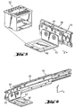
- tray 41 has an upper surface which is at least partially covered by a magnetic foil 42 as shown by Fig. 5.
- the magnetic force exerted by foil 42 is strong enough to ensure that component carrier 12 is kept on tray 41 during its transport, component carrier 12 is however revolvable about the Z-axis and is free to be moved along the X and Y axes, respectively.
- the above mentioned transport means for transporting component carrier 12 further comprise a transport device 14 for moving said tray 41 back and forth in horizontal direction along the X-axis towards and away from each of said loading bays 27 respectively 37.
- a preferred embodiment of transport device 14 is a telescopic arm 45 which has a movable part 44 and which is represented in Fig. 6. Tray 41 is attached to movable part 44 of telescopic arm 45. Telescopic arm 45 moves part 44 horizontally in X-direction shown in Fig. 6.
- telescopic arm 45 is adapted to extend its outer end to both sides of apparatus 11. On its way from one loading bay to the other movable part 44 of telescopic arm 45 passes through the middle of apparatus 11.
- Fig. 7 illustrates positioning of component carrier 12 in loading bay 27 by means of tray 41 moved by means of telescopic arm 45.
- loading bay 27 is mounted by means of supports 28 on a plate 29. Plate 29 is mounted on apparatus 22.
- Fig. 8 which illustrates positioning of component carrier 12 in loading bay 37
- the transport means according to the invention do not require that component carrier 12 be perfectly aligned with the position it has eventually to occupy in loading bay 37, because in a preferred embodiment each of the loading bays 27, 37 has guide surfaces which bring component carrier 12 into alignment with that position as component carrier 12 is moved by tray 41 and telescopic arm 45 into position 31 in loading bay 37.
- Broken line rectangle 12a illustrates the position taken by carrier 12 when it reaches position 31.
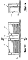
- Fig. 8a shows schematically a partial cross-sectional view of component carrier 12 and loading bay 37 in a plane normal to the X-axis in Fig. 8 when carrier 12 reaches position 12a in Fig. 8
- component carrier 12 has side walls each of which has at their upper end a shoulder 58 which rest on a top surface 59 of loading bay 37.
- a ferromagnetic metal piece 46 is lodged in at least one recess of shoulder 58.
- metal piece 46 lies in face of a permanent magnet 47 which is lodged in at least one recess of top surface 59 of loading bay 37.
- top surface 59 of loading bay is so shaped that it matches the shape of shoulder 58.
- Positioning of component carrier 12 at position 31 in loading bay 37 by means of the above mentioned transport means is performed in two steps.
- a first step carrier 12 is moved in X-direction towards loading bay 37 as represented in Fig. 8.
- this first step carrier 12 is maintained at a constant height (in Z-direction) at which shoulder 58 lies at a predetermined distance from and above top surface 59.
- guide surfaces 48, 49 guide carrier 12 so that when it reaches position 31 in loading bay 37 the symmetry axis 16 of carrier 12 substantially coincides with the central axis of loading bay 37 which coincides with the X-axis represented in Fig. 8.
- carrier 12 is slowly lowered.
- top surface 59 of loading bay 37 guides shoulder 58 of carrier 12 and at a given point metal piece 46 of carrier 12 is attracted and hold by magnet 47 of loading bay 37. In this way carrier 12 eventually reaches its final position 31 in loading bay 37 in all three directions (X-, Y- and Z-direction).
- Fig. 9 shows component carrier 12 duly positioned in loading bay 37.
- loading bay 37 is mounted by means of supports 38 on a plate 39.
- Plate 39 is mounted on apparatus 32.
- the above mentioned transport means for transporting component carrier 12 further comprise a transport device 15 for moving said tray 41 upwards and downwards in vertical direction along the Z-axis.
- Fig. 10 shows a preferred embodiment of an apparatus 11 according to the invention.
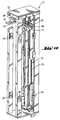
- Fig. 10 shows more in detail the above mentioned transport means 14 and 15.
- Transport device 15 comprises a carriage 77 which is moved upwards and downwards in vertical direction along the Z-axis by means of a toothed belt 78 driven by a gearmotor 79. Transport device 15 further includes a counterweight.
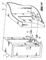
- housing 13 of apparatus 11 in Fig. 1 is connected to housing 23 of apparatus 22 by means of screw connections 24, 25, 26.
- These connections are represented more in detail in Fig. 11, which shows screws 64, 65, 66, bolts 74, 75, 76 and bolt holders 84, 85, 86 used to build screw connections 24, 25, 26.
- housing 13 of apparatus 11 in Fig. 1 is aligned to housing 33 of apparatus 32 by means of bolts 34, 35.
- This alignment is represented more in detail in Fig. 12, which shows bolts 67 and 68 and bolt holders 87 and 88 used to build contacts 34 and 35.
- the advantage of the above mentioned screw and bolt connections is that they make possible to align each of apparatuses 22 and 32, which have each a considerable weight, with an apparatus 11 according to the invention with the necessary accuracy, without special alignment equipment, and so that even when the apparatuses are connected and properly aligned with each other, each of the apparatuses stands on its own individual base.
- the above mentioned screw and bolt connections thus prevent that the apparatus walls which are in contact with each other have to bear unnecessary and unpredictable contact forces for alignment purposes. Preventing that such forces arise is advantageous, because it eliminates the need for a reinforcement of the frame structures of the apparatuses, which would be otherwise necessary.
- An apparatus according to the invention can be used in various configurations with at least two apparatuses which form part of an analyzer system.
- Fig. 13 shows a first configuration wherein a first embodiment of an apparatus 11 according to the invention is arranged between an apparatus 22 and an apparatus 32 which form part of an analyzer system. All three apparatuses are positioned on a table 96. Apparatus 11 provides the means for transporting a component carrier of the type described above between apparatuses 22 and 32.
- Fig. 14 shows a schematic side view showing of apparatuses 11 and 32 shown in Fig. 13.
- Fig. 15 shows a second embodiment of an apparatus 72 according to the invention arranged between apparatuses 22 and 91 on one side and an apparatus 32 on the opposite side.
- Apparatuses 22, 91 and 32 form part of an analyzer system.
- Apparatuses 22 and 32 are positioned on a table 97.
- Apparatus 91 is positioned under table 97.
- Apparatus 72 provides the means for transporting a component carrier of the type described above between all three apparatuses 22, 91 and 32.
- Fig. 16 is a schematic side view showing of apparatuses 72, 22 and 91 shown in Fig. 15.
- Apparatus 72 shown in Figures 15 and 16 is longer than apparatus 11 shown in Figures 13 and 14.
- apparatus 11 is preferably used for transporting a component carrier 12 between two apparatuses 22, 32 which for part of an analyzer system
- apparatus 72 is preferably used for transporting a component carrier 12 between three apparatuses 22, 32, 91 which for part of an analyzer system.
- FIG. 17 shows a block diagram of an analyzer system comprising several apparatuses 71, 72, 81 according to the invention and a number of apparatuses 22, 32, 91, 92, 93, 94 which form part of the analyzer system
- the operation of each of the apparatuses according to the invention is controlled by the control unit (CPU) of one of the apparatuses of the analyzer system it is connected to.
- the operation of apparatus 72 which provides transport of a component carrier 12 between apparatuses 22, 32 and 91, is controlled by block 104, which in turn is controlled by the CPU 102 of apparatus 22.
- Block 104 receives energy from power supply 103 of apparatus 22.
- apparatus 81 which provides transport of a component carrier between apparatuses 32, 92 and 94
- block 107 receives energy from power supply 106 of apparatus 32.
- apparatus 71 which provides transport of a component carrier between apparatuses 22, 91 and 93
- block 117 which in turn is controlled by the CPU 115 of apparatus 91.
- Block 117 receives energy from power supply 116 of apparatus 91.
Landscapes
- Physics & Mathematics (AREA)
- Health & Medical Sciences (AREA)
- Life Sciences & Earth Sciences (AREA)
- Chemical & Material Sciences (AREA)
- Analytical Chemistry (AREA)
- Biochemistry (AREA)
- General Health & Medical Sciences (AREA)
- General Physics & Mathematics (AREA)
- Immunology (AREA)
- Pathology (AREA)
- Automatic Analysis And Handling Materials Therefor (AREA)
- Control Of Conveyors (AREA)
Claims (9)
- Appareil pour transporter des composants dans un système d'analyse automatique, lequel appareil comprend :(a) un support de composants (2) permettant de maintenir plusieurs desdits composants ;(b) un mécanisme de transport (41, 14, 15) pour déplacer ledit support de composants (12) maintenant des composants système entre une première position (21) dans une première baie de chargement (27) dans un premier boîtier (23), et une seconde position (31) dans une seconde baie de chargement (37) dans un second boîtier (33) ; et(c) un boîtier de transport (13) pour ledit mécanisme de transport (41, 14, 15), ledit boîtier de transport (13), ledit premier boîtier (23) et ledit second boîtier (33) comportant chacun des moyens de connexion permettant de connecter ledit premier boîtier (23) et ledit second boîtier (33) au boîtier de transport (13) et de les aligner par rapport à ce dernier ;lequel appareil est caractérisé en ce que :- ledit mécanisme de transport (41, 14, 15) comprend un plateau mobile (41) conçu pour recevoir et transporter ledit support de composants (12) qui y est placé dessus ;- ledit support de composants (12) peut être retiré dudit plateau (41) ;- ledit support de composants (12), pendant qu'il est maintenu sur ledit plateau (41), peut se déplacer librement par rapport au dit plateau (41) afin d'être correctement positionné au niveau d'une desdites baies de chargement (27, 37) ; et- ledit support de composants (12) peut maintenir au moins un composant devant être analysé par le système.
- Appareil selon la revendication 1, dans lequel ledit support de composants (12) consiste en une boîte creuse (51) comportant diverses ouvertures (52 à 55) et chambres (56) servant à maintenir plusieurs composants (61, 62) de tailles et de formes différentes, laquelle boîte (51) comprend une paroi de fond (57) dont la surface externe comprend au moins une partie métallique pouvant être maintenue par une force magnétique.
- Appareil selon la revendication 1, dans lequel ledit support de composants (12) est maintenu en position sur ledit plateau (41) par un moyen magnétique pendant le mouvement dudit plateau entre lesdits premier et second appareils (22, 32).
- Appareil selon la revendication 3, dans lequel ledit plateau mobile (41) possède une surface supérieure qui est au moins partiellement couverte par une feuille magnétique (42) .
- Appareil selon la revendication 1, dans lequel ledit mécanisme de transport comprend en outre un premier dispositif de transport (14) pour déplacer ledit plateau (41) dans le sens horizontal et l'approcher et l'éloigner de chacune desdites première et seconde positions (21, 31), respectivement.
- Appareil selon la revendication 5, dans lequel ledit premier dispositif de transport (14) consiste en un bras télescopique (45), ledit plateau (41) étant fixé à une partie mobile (44) dudit bras télescopique (45).
- Appareil selon la revendication 5, dans lequel ledit mécanisme de transport comprend un second dispositif de transport (15) permettant de déplacer ledit premier dispositif de transport (14) vers le bas et vers le haut dans le sens vertical.
- Appareil selon l'une quelconque des revendications 3 à 7, dans lequel ledit support de composants (12) et/ou ladite baie de chargement (27, 37) comprennent des moyens (46, 47) qui s'attirent l'un l'autre grâce à une force magnétique et qui contribuent à définir avec précision une position prédéterminée dudit support par rapport à ladite baie de chargement.
- Appareil selon l'une quelconque des revendications 1 à 8, dans lequel le fonctionnement dudit mécanisme de transport (41, 14, 15) est commandé par une unité de commande (104) qui fait partie du mécanisme de transport.
Priority Applications (6)
| Application Number | Priority Date | Filing Date | Title |
|---|---|---|---|
| EP98810974A EP0990906B1 (fr) | 1998-09-28 | 1998-09-28 | Dispositif de transport de composants dans un système d'analyses automatisé |
| DE69833846T DE69833846T2 (de) | 1998-09-28 | 1998-09-28 | Vorrichtung zum Befördern von Komponenten innerhalb eines automatischen Analysesystems |
| ES98810974T ES2259452T3 (es) | 1998-09-28 | 1998-09-28 | Aparato para transportar componentes dentro de un sistema analizador automatico. |
| AT98810974T ATE320609T1 (de) | 1998-09-28 | 1998-09-28 | Vorrichtung zum transport von gegenständen in eines automatisches analysesystem |
| US09/396,157 US6403035B1 (en) | 1998-09-28 | 1999-09-14 | Apparatus for transporting components within an automatic analyzer system |
| JP26169999A JP4225649B2 (ja) | 1998-09-28 | 1999-09-16 | 自動分析器システム内で構成要素を移動させる装置 |
Applications Claiming Priority (1)
| Application Number | Priority Date | Filing Date | Title |
|---|---|---|---|
| EP98810974A EP0990906B1 (fr) | 1998-09-28 | 1998-09-28 | Dispositif de transport de composants dans un système d'analyses automatisé |
Publications (2)
| Publication Number | Publication Date |
|---|---|
| EP0990906A1 EP0990906A1 (fr) | 2000-04-05 |
| EP0990906B1 true EP0990906B1 (fr) | 2006-03-15 |
Family
ID=8236354
Family Applications (1)
| Application Number | Title | Priority Date | Filing Date |
|---|---|---|---|
| EP98810974A Expired - Lifetime EP0990906B1 (fr) | 1998-09-28 | 1998-09-28 | Dispositif de transport de composants dans un système d'analyses automatisé |
Country Status (6)
| Country | Link |
|---|---|
| US (1) | US6403035B1 (fr) |
| EP (1) | EP0990906B1 (fr) |
| JP (1) | JP4225649B2 (fr) |
| AT (1) | ATE320609T1 (fr) |
| DE (1) | DE69833846T2 (fr) |
| ES (1) | ES2259452T3 (fr) |
Cited By (1)
| Publication number | Priority date | Publication date | Assignee | Title |
|---|---|---|---|---|
| US7628954B2 (en) | 2005-05-04 | 2009-12-08 | Abbott Laboratories, Inc. | Reagent and sample handling device for automatic testing system |
Families Citing this family (23)
| Publication number | Priority date | Publication date | Assignee | Title |
|---|---|---|---|---|
| ITMI20030550A1 (it) * | 2003-03-21 | 2004-09-22 | Delta Biolog S R L | Macchina ad architettura modulare per l'esecuzione di analisi mediche. |
| EP1582874B1 (fr) * | 2004-03-31 | 2008-07-09 | Roche Diagnostics GmbH | Appareil modulaire pour analyses |
| EP1582875A1 (fr) * | 2004-03-31 | 2005-10-05 | Boehringer Mannheim Gmbh | Analyseur avec ascenseur |
| US7914737B2 (en) * | 2004-07-01 | 2011-03-29 | Roche Molecular Systems, Inc. | Multi-level diagnostic apparatus with a lift system |
| CA2842402C (fr) * | 2005-03-10 | 2016-02-23 | Gen-Probe Incorporated | Systemes et procedes permettant d'effectuer des dosages afin de detecter ou de quantifier des analytes dans des echantillons |
| WO2012074885A1 (fr) * | 2010-11-24 | 2012-06-07 | Hologic, Inc. | Système pour une manipulation améliorée de tissu et analyse du tissu en ligne |
| WO2014144825A2 (fr) | 2013-03-15 | 2014-09-18 | Abbott Laboratories | Gestionnaire de réactif automatisé de système analyseur de diagnostic |
| US9632103B2 (en) | 2013-03-15 | 2017-04-25 | Abbott Laboraties | Linear track diagnostic analyzer |
| WO2014144870A2 (fr) | 2013-03-15 | 2014-09-18 | Abbott Laboratories | Système de blocage de lumière pour un analyseur de diagnostic |
| WO2015134277A1 (fr) | 2014-03-05 | 2015-09-11 | Faxitron Bioptics, Llc | Système et procédé pour imagerie multiaxiale de spécimens |
| JP6496211B2 (ja) * | 2015-08-12 | 2019-04-03 | 日本電子株式会社 | 検体ラック搬送装置及び自動分析システム |
| WO2017040977A1 (fr) | 2015-09-04 | 2017-03-09 | Faxitron Bioptics, Llc | Dispositif d'imagerie d'échantillons multi-axe avec marqueurs d'orientation incorporés |
| JP2019519790A (ja) * | 2016-07-01 | 2019-07-11 | デビコー・メディカル・プロダクツ・インコーポレイテッドDevicor Medical Products, Inc. | 乳房生検処置から得た組織試料の処置のための統合されたワークフロー優先権 |
| US11083426B2 (en) | 2016-11-04 | 2021-08-10 | Hologic, Inc. | Specimen radiography system comprising cabinet and a specimen drawer positionable by a controller in the cabinet |
| US12161307B2 (en) | 2017-05-03 | 2024-12-10 | Hologic, Inc. | Devices and methods for reducing fluid in the imaging field of a tissue handling apparatus for improving biopsy system imaging quality |
| EP3682228B1 (fr) | 2017-09-11 | 2025-12-17 | Faxitron Bioptics, LLC | Système d'imagerie à grossissement d'objet adaptatif |
| EP3902473B1 (fr) | 2018-12-26 | 2023-02-01 | Hologic, Inc. | Imagerie tissulaire en présence de liquide pendant une intervention de biopsie |
| WO2021202455A1 (fr) | 2020-03-31 | 2021-10-07 | Hologic, Inc. | Systèmes et procédés de radiographie d'échantillons de tissu |
| US12396693B2 (en) | 2020-09-16 | 2025-08-26 | Hologic, Inc. | Systems and methods for confirming tissue specimens removed using contrast-enhanced x-ray imaging |
| DE102024101354A1 (de) | 2024-01-17 | 2025-07-17 | Hamilton Bonaduz Ag | Pipettier-Labormodul mit besonderer Beschickung der Pipettiervorrichtung des Pipettier-Labormoduls |
| DE102024101358A1 (de) | 2024-01-17 | 2025-07-17 | Hamilton Bonaduz Ag | Labormoduletagere aus übereinander angeordneten Labormodulen |
| DE102024101352A1 (de) | 2024-01-17 | 2025-07-17 | Hamilton Bonaduz Ag | Labormodul mit einander einen Transportgegenstand abstreifend übergebenden Transportvorrichtungen |
| DE102024101357A1 (de) | 2024-01-17 | 2025-07-17 | Hamilton Bonaduz Ag | Labormodul mit einer Liefer-Transportvorrichtung mit zwei Liefer-Aufnahmeeinrichtungen zur Aufnahme von je wenigstens einem Laborgegenstand |
Family Cites Families (11)
| Publication number | Priority date | Publication date | Assignee | Title |
|---|---|---|---|---|
| DE3841961A1 (de) * | 1988-12-14 | 1990-06-21 | Dynatech Ag Branch Denkendorf | Geraet zur analyse von physiologischen oder anderen fluessigkeiten in den vertiefungen einer mikrotestplatte |
| US5207986A (en) * | 1990-03-30 | 1993-05-04 | Shimadzu Corporation | Automatic analyzer |
| IT1260447B (it) * | 1992-01-27 | 1996-04-09 | Procedimento e apparecchiatura per l'automazione integrale di un laboratorio di analisi | |
| DE4306332A1 (de) * | 1993-02-24 | 1994-08-25 | Mannesmann Ag | Vorrichtung zum Wechseln von Meß- und/oder Probensonden |
| US5735387A (en) * | 1995-07-14 | 1998-04-07 | Chiron Diagnostics Corporation | Specimen rack handling system |
| JP3031237B2 (ja) * | 1996-04-10 | 2000-04-10 | 株式会社日立製作所 | 検体ラックの搬送方法及び検体ラックを搬送する自動分析装置 |
| CA2255839A1 (fr) * | 1996-07-05 | 1998-01-15 | Mark Gross | Systeme automatise de traitement d'echantillons |
| JP3032159B2 (ja) * | 1996-09-24 | 2000-04-10 | 株式会社日立製作所 | 分析システム |
| JP3336894B2 (ja) * | 1997-01-29 | 2002-10-21 | 株式会社日立製作所 | 自動分析装置 |
| EP0918221B1 (fr) * | 1997-11-19 | 2006-09-06 | Grifols, S.A. | Appareil pour réaliser automatiquement des tests de laboratoire |
| DE19819812C2 (de) * | 1998-05-04 | 2000-11-02 | Olympus Diagnostica Gmbh | Laborprimärprobenverteiler mit einer Verteileinrichtung |
-
1998
- 1998-09-28 ES ES98810974T patent/ES2259452T3/es not_active Expired - Lifetime
- 1998-09-28 DE DE69833846T patent/DE69833846T2/de not_active Expired - Lifetime
- 1998-09-28 AT AT98810974T patent/ATE320609T1/de active
- 1998-09-28 EP EP98810974A patent/EP0990906B1/fr not_active Expired - Lifetime
-
1999
- 1999-09-14 US US09/396,157 patent/US6403035B1/en not_active Expired - Lifetime
- 1999-09-16 JP JP26169999A patent/JP4225649B2/ja not_active Expired - Lifetime
Cited By (2)
| Publication number | Priority date | Publication date | Assignee | Title |
|---|---|---|---|---|
| US7628954B2 (en) | 2005-05-04 | 2009-12-08 | Abbott Laboratories, Inc. | Reagent and sample handling device for automatic testing system |
| US9057714B2 (en) | 2005-05-04 | 2015-06-16 | Abbott Laboratories | Reagent and sample handling device for automatic testing system |
Also Published As
| Publication number | Publication date |
|---|---|
| EP0990906A1 (fr) | 2000-04-05 |
| JP4225649B2 (ja) | 2009-02-18 |
| JP2000105244A (ja) | 2000-04-11 |
| ATE320609T1 (de) | 2006-04-15 |
| ES2259452T3 (es) | 2006-10-01 |
| DE69833846D1 (de) | 2006-05-11 |
| DE69833846T2 (de) | 2006-10-26 |
| US6403035B1 (en) | 2002-06-11 |
Similar Documents
| Publication | Publication Date | Title |
|---|---|---|
| US6403035B1 (en) | Apparatus for transporting components within an automatic analyzer system | |
| JP4719211B2 (ja) | 自動化された臨床機器のための磁気検体搬送システム | |
| US7670555B2 (en) | Parallel gripper for handling multiwell plate | |
| US7264111B2 (en) | Magnetic specimen-transport system for automated clinical instrument | |
| JP4125735B2 (ja) | モジュラー装置 | |
| US9101922B2 (en) | Methods for using a pipetting device with independently movable pipette units | |
| CN112122014B (zh) | 一种适用于全自动试样离心的进样装置 | |
| US20070214900A1 (en) | Apparatus for transferring samples from source vessels to target vessels | |
| EP1361440A1 (fr) | Méthode et appareil pour le transport d'une pluralité de tubes à essai dans un système de mesure | |
| CN113382803B (zh) | 用于自动处理实验室样品的实验室自动机 | |
| KR20180132142A (ko) | 액체 핸들링을 위한 소모품 조작 | |
| CN218180444U (zh) | 样品制备工作站及样品制备系统 | |
| JP2023125975A (ja) | 試料調製装置、試料処理装置、試料調製方法および試料処理方法 | |
| US6823041B2 (en) | Grasping system for automated exchange of elongated samples in an X-ray analysis apparatus | |
| CN212010592U (zh) | 自动充测一体机设备 | |
| EP3862756B1 (fr) | Montage réglable pour applications de manipulation automatique de liquides | |
| US20030048870A1 (en) | X-ray analysis apparatus | |
| CN214427456U (zh) | 一种全自动化检测平台 | |
| CN212341426U (zh) | 磁导率测试治具 | |
| CN219092386U (zh) | 一种自动加样和搬运的离心系统 | |
| WO1993014909A1 (fr) | Appareil de chargement, dechargement et de positionnement precis d'articles par rapport a une table | |
| CN118358947A (zh) | 医用耗材转移装置及具有其的核酸检测一体机 | |
| EP4722330A1 (fr) | Appareil d'extraction d'échantillon | |
| JP2008518796A (ja) | 付属装置を結合するための装置 | |
| CN120652116A (zh) | 一种生物体液样本的检测装置 |
Legal Events
| Date | Code | Title | Description |
|---|---|---|---|
| PUAI | Public reference made under article 153(3) epc to a published international application that has entered the european phase |
Free format text: ORIGINAL CODE: 0009012 |
|
| AK | Designated contracting states |
Kind code of ref document: A1 Designated state(s): AT CH DE ES FR GB IT LI NL |
|
| AX | Request for extension of the european patent |
Free format text: AL;LT;LV;MK;RO;SI |
|
| 17P | Request for examination filed |
Effective date: 20000712 |
|
| AKX | Designation fees paid |
Free format text: AT CH DE ES FR GB IT LI NL |
|
| 17Q | First examination report despatched |
Effective date: 20010420 |
|
| GRAP | Despatch of communication of intention to grant a patent |
Free format text: ORIGINAL CODE: EPIDOSNIGR1 |
|
| GRAS | Grant fee paid |
Free format text: ORIGINAL CODE: EPIDOSNIGR3 |
|
| GRAA | (expected) grant |
Free format text: ORIGINAL CODE: 0009210 |
|
| AK | Designated contracting states |
Kind code of ref document: B1 Designated state(s): AT CH DE ES FR GB IT LI NL |
|
| REG | Reference to a national code |
Ref country code: GB Ref legal event code: FG4D Ref country code: CH Ref legal event code: EP |
|
| REG | Reference to a national code |
Ref country code: CH Ref legal event code: NV Representative=s name: VENTOCILLA PATENT AG |
|
| REF | Corresponds to: |
Ref document number: 69833846 Country of ref document: DE Date of ref document: 20060511 Kind code of ref document: P |
|
| REG | Reference to a national code |
Ref country code: ES Ref legal event code: FG2A Ref document number: 2259452 Country of ref document: ES Kind code of ref document: T3 |
|
| ET | Fr: translation filed | ||
| PLBE | No opposition filed within time limit |
Free format text: ORIGINAL CODE: 0009261 |
|
| STAA | Information on the status of an ep patent application or granted ep patent |
Free format text: STATUS: NO OPPOSITION FILED WITHIN TIME LIMIT |
|
| 26N | No opposition filed |
Effective date: 20061218 |
|
| REG | Reference to a national code |
Ref country code: CH Ref legal event code: NV Representative=s name: ROCHE DIAGNOSTICS AG |
|
| PGFP | Annual fee paid to national office [announced via postgrant information from national office to epo] |
Ref country code: AT Payment date: 20110825 Year of fee payment: 14 Ref country code: ES Payment date: 20110905 Year of fee payment: 14 |
|
| PGFP | Annual fee paid to national office [announced via postgrant information from national office to epo] |
Ref country code: NL Payment date: 20110912 Year of fee payment: 14 Ref country code: IT Payment date: 20110922 Year of fee payment: 14 |
|
| REG | Reference to a national code |
Ref country code: CH Ref legal event code: PFA Owner name: F. HOFFMANN-LA ROCHE AG, CH Free format text: FORMER OWNER: F. HOFFMANN-LA ROCHE AG, CH |
|
| REG | Reference to a national code |
Ref country code: NL Ref legal event code: V1 Effective date: 20130401 |
|
| REG | Reference to a national code |
Ref country code: AT Ref legal event code: MM01 Ref document number: 320609 Country of ref document: AT Kind code of ref document: T Effective date: 20120928 |
|
| PG25 | Lapsed in a contracting state [announced via postgrant information from national office to epo] |
Ref country code: AT Free format text: LAPSE BECAUSE OF NON-PAYMENT OF DUE FEES Effective date: 20120928 |
|
| PG25 | Lapsed in a contracting state [announced via postgrant information from national office to epo] |
Ref country code: IT Free format text: LAPSE BECAUSE OF NON-PAYMENT OF DUE FEES Effective date: 20120928 Ref country code: NL Free format text: LAPSE BECAUSE OF NON-PAYMENT OF DUE FEES Effective date: 20130401 |
|
| REG | Reference to a national code |
Ref country code: ES Ref legal event code: FD2A Effective date: 20131021 |
|
| PG25 | Lapsed in a contracting state [announced via postgrant information from national office to epo] |
Ref country code: ES Free format text: LAPSE BECAUSE OF NON-PAYMENT OF DUE FEES Effective date: 20120929 |
|
| REG | Reference to a national code |
Ref country code: FR Ref legal event code: PLFP Year of fee payment: 19 |
|
| REG | Reference to a national code |
Ref country code: FR Ref legal event code: PLFP Year of fee payment: 20 |
|
| PGFP | Annual fee paid to national office [announced via postgrant information from national office to epo] |
Ref country code: CH Payment date: 20170725 Year of fee payment: 20 Ref country code: GB Payment date: 20170829 Year of fee payment: 20 Ref country code: FR Payment date: 20170823 Year of fee payment: 20 |
|
| PGFP | Annual fee paid to national office [announced via postgrant information from national office to epo] |
Ref country code: DE Payment date: 20170928 Year of fee payment: 20 |
|
| REG | Reference to a national code |
Ref country code: DE Ref legal event code: R071 Ref document number: 69833846 Country of ref document: DE |
|
| REG | Reference to a national code |
Ref country code: CH Ref legal event code: PL |
|
| REG | Reference to a national code |
Ref country code: GB Ref legal event code: PE20 Expiry date: 20180927 |
|
| PG25 | Lapsed in a contracting state [announced via postgrant information from national office to epo] |
Ref country code: GB Free format text: LAPSE BECAUSE OF EXPIRATION OF PROTECTION Effective date: 20180927 |