EP0990914A2 - Appareil de test d'un connecteur avec conducteur de lumiére - Google Patents
Appareil de test d'un connecteur avec conducteur de lumiére Download PDFInfo
- Publication number
- EP0990914A2 EP0990914A2 EP99116958A EP99116958A EP0990914A2 EP 0990914 A2 EP0990914 A2 EP 0990914A2 EP 99116958 A EP99116958 A EP 99116958A EP 99116958 A EP99116958 A EP 99116958A EP 0990914 A2 EP0990914 A2 EP 0990914A2
- Authority
- EP
- European Patent Office
- Prior art keywords
- test
- sleeve
- pin
- test device
- connector
- Prior art date
- Legal status (The legal status is an assumption and is not a legal conclusion. Google has not performed a legal analysis and makes no representation as to the accuracy of the status listed.)
- Withdrawn
Links
- 239000004020 conductor Substances 0.000 title abstract 3
- 230000008878 coupling Effects 0.000 claims abstract description 3
- 238000010168 coupling process Methods 0.000 claims abstract description 3
- 238000005859 coupling reaction Methods 0.000 claims abstract description 3
- 239000013307 optical fiber Substances 0.000 claims description 11
- 238000011156 evaluation Methods 0.000 description 3
- 230000002950 deficient Effects 0.000 description 1
- 239000000835 fiber Substances 0.000 description 1
- 238000003780 insertion Methods 0.000 description 1
- 230000037431 insertion Effects 0.000 description 1
- 238000012423 maintenance Methods 0.000 description 1
- 230000003287 optical effect Effects 0.000 description 1
- 239000000523 sample Substances 0.000 description 1
- 238000000926 separation method Methods 0.000 description 1
Images
Classifications
-
- G—PHYSICS
- G01—MEASURING; TESTING
- G01M—TESTING STATIC OR DYNAMIC BALANCE OF MACHINES OR STRUCTURES; TESTING OF STRUCTURES OR APPARATUS, NOT OTHERWISE PROVIDED FOR
- G01M11/00—Testing of optical apparatus; Testing structures by optical methods not otherwise provided for
- G01M11/30—Testing of optical devices, constituted by fibre optics or optical waveguides
- G01M11/31—Testing of optical devices, constituted by fibre optics or optical waveguides with a light emitter and a light receiver being disposed at the same side of a fibre or waveguide end-face, e.g. reflectometers
Definitions
- the present invention relates to a test device for equipped with optical fibers Plug according to the preamble of claim 1.
- Such a test device is known from DE 297 16 026.
- an optical waveguide Test pin is connected to a receiver via an optical fiber. This compares the received signals with a defined value, the signals from a transmitter that is connected to the other end of the optical fiber, which is plugged into and connected to the plug and its flawless Continuity should be determined.
- the fiber optic cable connects the test pin with the receiver or connects the transmitter, losses occur, for example, in damage to the optical fiber between the test pin and the receiver or the sender may be justified.
- the present invention is therefore based on the object of a test device to further develop the generic type so that its operational safety increases and operating costs due to the possibility of maintenance and repair to be carried out more easily and quickly. This task is solved by a test device having the features of claim 1.
- test device has the advantage that no additional Optical fiber from the test pin to the receiver or transmitter is required.
- test head is detachably attached to the test pin, for example by screwing.
- test head is easily accessible from the connector receptacle and is easy to use to remove and replace, which of course has considerable assembly advantages result in particular from shorter business interruption times.
- Both the receiver and the transmitter consist in a manner known per se Diodes that are offered as commercially available components at extremely low prices. Their Procurement costs are disproportionate to the previously high assembly costs.
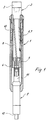
- test pin 1 which has a sleeve 4, which is not in one shown coupling part is fixed.
- a threaded bushing 10 is screwed into the sleeve 4, on the threaded bushing 10 an external and in the sleeve 4 an internal thread 6, 7 are provided.
- a bush 9 is axially displaceable, in which a test head 2 is arranged with a receiver diode 3.
- a transmitter diode can also be provided.
- the receiver diode 3 is on one Piston 8 connected, which is fixed in the socket 9.
- the socket 9 On the end face opposite the test head 2, the socket 9 is supported on one Contact pin 11, which is spring-loaded and axially displaceable in a contact sleeve 5 is guided, which is firmly connected to the sleeve 4.
- the spring force acts in the direction of the socket 9, so that a connector to be tested only by pressing the test head 2 against this spring force into the not shown Plug receptacle can be used.
- a line 12 is connected to the contact sleeve 5 and is equipped with an evaluation electronics communicates.
- the threaded bushing 10 In order to replace the test head 2, the threaded bushing 10 must be unscrewed from the sleeve 4, the threaded bushing 10 expediently has a tool holder on the top, for example in the form of a hexagon, so that an insertion from above or unscrewing is easily possible.
Landscapes
- Physics & Mathematics (AREA)
- Optics & Photonics (AREA)
- Chemical & Material Sciences (AREA)
- Analytical Chemistry (AREA)
- General Physics & Mathematics (AREA)
- Mechanical Coupling Of Light Guides (AREA)
- Details Of Connecting Devices For Male And Female Coupling (AREA)
Applications Claiming Priority (2)
| Application Number | Priority Date | Filing Date | Title |
|---|---|---|---|
| DE29817515U DE29817515U1 (de) | 1998-10-01 | 1998-10-01 | Prüfeinrichtung für mit Lichtwellenleitern bestückte Stecker |
| DE29817515U | 1998-10-01 |
Publications (2)
| Publication Number | Publication Date |
|---|---|
| EP0990914A2 true EP0990914A2 (fr) | 2000-04-05 |
| EP0990914A3 EP0990914A3 (fr) | 2002-09-25 |
Family
ID=8063328
Family Applications (1)
| Application Number | Title | Priority Date | Filing Date |
|---|---|---|---|
| EP99116958A Withdrawn EP0990914A3 (fr) | 1998-10-01 | 1999-08-27 | Appareil de test d'un connecteur avec conducteur de lumiére |
Country Status (2)
| Country | Link |
|---|---|
| EP (1) | EP0990914A3 (fr) |
| DE (1) | DE29817515U1 (fr) |
Families Citing this family (1)
| Publication number | Priority date | Publication date | Assignee | Title |
|---|---|---|---|---|
| DE19952418A1 (de) * | 1999-10-30 | 2001-06-28 | Tsk Pruefsysteme Fuer Elek Sch | Verfahren zur Prüfung eines Lichtwellenleiters |
Family Cites Families (4)
| Publication number | Priority date | Publication date | Assignee | Title |
|---|---|---|---|---|
| FR2547424B1 (fr) * | 1983-06-08 | 1986-07-04 | Commissariat Energie Atomique | Connecteur optique, procede de fabrication dudit connecteur et connexions fibres - fibres et diodes - fibres realisees avec ce connecteur |
| US4802726A (en) * | 1987-10-08 | 1989-02-07 | American Telephone And Telegraph Company, At&T Technologies, Inc. | Methods of and apparatus for reconfiguring optical fiber connector components and products produced thereby |
| JP2538394Y2 (ja) * | 1991-05-29 | 1997-06-11 | 住友電気工業株式会社 | 光コネクタ |
| FR2691264B1 (fr) * | 1992-05-12 | 1995-02-10 | Aerospatiale | Système de raccordement de liaisons optiques à des liaisons électriques. |
-
1998
- 1998-10-01 DE DE29817515U patent/DE29817515U1/de not_active Expired - Lifetime
-
1999
- 1999-08-27 EP EP99116958A patent/EP0990914A3/fr not_active Withdrawn
Also Published As
| Publication number | Publication date |
|---|---|
| DE29817515U1 (de) | 1998-12-10 |
| EP0990914A3 (fr) | 2002-09-25 |
Similar Documents
| Publication | Publication Date | Title |
|---|---|---|
| DE2812284C2 (de) | Ausrichtvorrichtung für optische Einzelfaserleitungen | |
| DE69212464T2 (de) | Faseroptischer stecker und montageverfahren | |
| DE3022102C1 (de) | Koaxialer HF-Steckerverbinder | |
| DE102008048440B4 (de) | Mittelpufferkupplung für schienengebundene Fahrzeuge | |
| EP1006378B1 (fr) | Connexion enfichable comportant une pluralité de guides d'onde disposés en parallel | |
| EP0164531B1 (fr) | Connecteur à fiches pour guides d'ondes lumineuses | |
| EP0516930B1 (fr) | Dispositif pour connecter des conduites | |
| EP0290989B1 (fr) | Prise de courant montée flottante sur une plaque de montage | |
| DE3124546C2 (fr) | ||
| EP0982215B1 (fr) | Ensemble pour véhicule ferroviaire, composé d'un accouplement central et d'un accouplement de câbles électriques | |
| EP0442056A2 (fr) | Connexion à fibre optique | |
| DE69328958T2 (de) | Faseroptische Justiervorrichtung | |
| DE3517388A1 (de) | Anschlussteil fuer ein faser-optisches kabel | |
| DE10310148A1 (de) | Lichtleiterkupplung | |
| DE2939231A1 (de) | Mehrfachstecker zum anschluss einer glasfaserleitung an einen opto-elektrischen baustein | |
| DE69131026T2 (de) | Optischer Steckverbinder mit Adapter mit Vorrichtung zum Schliessen und Trennen des optischen Kontakts | |
| DE10240563B4 (de) | Kupplung für Koaxialkabel | |
| EP0990914A2 (fr) | Appareil de test d'un connecteur avec conducteur de lumiére | |
| DE19830148C1 (de) | Anschlußelement für ein Lichtwellenleiterkabel | |
| DE8019236U1 (de) | Anschlußvorrichtung für ein abgeschirmtes Kabel | |
| EP1537447A1 (fr) | Connecteur | |
| DE19729978A1 (de) | Vorrichtung zum lösbaren Verbinden zweier Lichtleiter oder Lichtleiterbündel miteinander | |
| EP0582745A1 (fr) | Système de câblage et installation pour des arrangements équipés de guides d'ondes lumineuses | |
| DE19952420C2 (de) | Verfahren und Vorrichtung zur Durchgängigkeitsprüfung für einen Lichtwellenleiter | |
| DE3920990C2 (fr) |
Legal Events
| Date | Code | Title | Description |
|---|---|---|---|
| PUAI | Public reference made under article 153(3) epc to a published international application that has entered the european phase |
Free format text: ORIGINAL CODE: 0009012 |
|
| AK | Designated contracting states |
Kind code of ref document: A2 Designated state(s): AT BE CH CY DE DK ES FI FR GB GR IE IT LI LU MC NL PT SE |
|
| AX | Request for extension of the european patent |
Free format text: AL;LT;LV;MK;RO;SI |
|
| PUAL | Search report despatched |
Free format text: ORIGINAL CODE: 0009013 |
|
| AK | Designated contracting states |
Kind code of ref document: A3 Designated state(s): AT BE CH CY DE DK ES FI FR GB GR IE IT LI LU MC NL PT SE |
|
| AX | Request for extension of the european patent |
Free format text: AL;LT;LV;MK;RO;SI |
|
| 17P | Request for examination filed |
Effective date: 20030306 |
|
| AKX | Designation fees paid |
Designated state(s): AT BE CH CY DE DK ES FI FR GB GR IE IT LI LU MC NL PT SE |
|
| 17Q | First examination report despatched |
Effective date: 20071113 |
|
| STAA | Information on the status of an ep patent application or granted ep patent |
Free format text: STATUS: THE APPLICATION IS DEEMED TO BE WITHDRAWN |
|
| 18D | Application deemed to be withdrawn |
Effective date: 20080301 |