EP0990971A1 - Configuration d'un ordinateur pour interfacer à un suppport de données sécurisé - Google Patents
Configuration d'un ordinateur pour interfacer à un suppport de données sécurisé Download PDFInfo
- Publication number
- EP0990971A1 EP0990971A1 EP99200433A EP99200433A EP0990971A1 EP 0990971 A1 EP0990971 A1 EP 0990971A1 EP 99200433 A EP99200433 A EP 99200433A EP 99200433 A EP99200433 A EP 99200433A EP 0990971 A1 EP0990971 A1 EP 0990971A1
- Authority
- EP
- European Patent Office
- Prior art keywords
- configuration
- controller
- data
- controller means
- physical link
- Prior art date
- Legal status (The legal status is an assumption and is not a legal conclusion. Google has not performed a legal analysis and makes no representation as to the accuracy of the status listed.)
- Withdrawn
Links
Images


Classifications
-
- G—PHYSICS
- G06—COMPUTING OR CALCULATING; COUNTING
- G06F—ELECTRIC DIGITAL DATA PROCESSING
- G06F21/00—Security arrangements for protecting computers, components thereof, programs or data against unauthorised activity
- G06F21/70—Protecting specific internal or peripheral components, in which the protection of a component leads to protection of the entire computer
- G06F21/82—Protecting input, output or interconnection devices
- G06F21/83—Protecting input, output or interconnection devices input devices, e.g. keyboards, mice or controllers thereof
-
- G—PHYSICS
- G06—COMPUTING OR CALCULATING; COUNTING
- G06F—ELECTRIC DIGITAL DATA PROCESSING
- G06F21/00—Security arrangements for protecting computers, components thereof, programs or data against unauthorised activity
- G06F21/70—Protecting specific internal or peripheral components, in which the protection of a component leads to protection of the entire computer
- G06F21/82—Protecting input, output or interconnection devices
- G06F21/85—Protecting input, output or interconnection devices interconnection devices, e.g. bus-connected or in-line devices
Definitions
- the invention relates to a system as recited in the preamble of Claim 1.
- smart cards and other secure data carriers are being used in relatively uncontrolled environments, such as Personal Computer configurations based at customer premises, and which configurations find application for transferring confidential information to remote places.
- trusted hardware has been designed.
- the precise locating of such trusted hardware is a problem that should be subject to requirements for high security and low cost.
- the amending as well as the acquiring of such secret information by non-entitled parties should be avoided with a very high probability, while still allowing a user person to enter secret informations such as PIN codes on a standard keyboard by rendering secure all communication between the keyboard and higher-level data-processing facilities.
- the invention can in principle be applied with magstripe cards as well. In such case, there is a security barrier within a reader to avoid leakage of secret information. Smart cards have such barrier on the card itself to block external presentation of the card's PIN code
- the invention also relates to a Method for Operating such Configuration, and to Keyboard Means, Communication Path Means, Consumer Level Computer Means, and Packaged Trusted Hardware Means arranged for application in a system according to the invention. Further advantageous aspects of the invention are recited in dependent Claims.
- Smart-cards are a secure and widespread computing platform well-suited to provide high security and privacy functionality for applications running in general purpose computing environments such as Personal Computers. Smart-cards store sensitive information such as private keys, account numbers, passwords and other. They also provide isolated processing facility to use this information without exposing it within a PC environment where it is at risk from hostile code.
- Readers are available in the market. Low cost readers do not have an integrated display or a keyboard, and are not acceptable for payments over the Internet. In such application it is necessary to enter the PIN code, the amount of money to be transferred, and possibly, other security quantities, and a confirmation display of the transferred sum is necessary.
- readers featuring a display and a keyboard are not trusted hardware such as shown in Figure 1A.
- the PC is used as interface with the application software running thereon. The latter can be affected by a virus program and get the PIN code from the user. Also the amount of money to be transferred may be changed. Even the confirmation button can be simulated by a virus program.
- integrating the reader in the PC cabinet will cause problems as this necessitates a separate keyboard to enter the PIN code and the amount of money. This will be mechanically difficult and expensive.
- Figure 2A shows a solution with a low-cost external card reader.
- Data go from the PC-keyboard via the Keyboard controller, ISA bus, south bridge, and the PCI bus to the north bridge.
- the data will be processed by the application running on the CPU and Memory.
- the application will send information back via the PCI, ISA and the Serial I/O to the micro-controller on the Smart card reader and thence to the Smart-card itself.
- the data may be manipulated by a virus program
- Figure 2B presents a solution with a fully qualified external card reader. Now, the data will be entered on the keyboard of the reader. The data will go into the microcontroller and then to the smart-card. Here, the data going towards the Smart-card cannot be manipulated by a Virus Program running on the main CPU.
- FIG. 3 shows an embodiment of the invention realized in special hardware.
- a request by the smart-card for data input will get known in the Smart-card controller, which will switch-over the PC-keyboard signals from the PC-keyboard controller to the Smart-card controller.
- Data may be entered into the keyboard and will go through the smart-card controller and towards the Smart-card itself. Now a virus program running on the main CPU can no more manipulate the data. If the data have been entered, an appropriate control signal will switch the data path from the PC-keyboard back to the normal keyboard controller.
- compatibility problems viz a viz the software may occur.
- Figure 4 shows a solution with integration in the Super I/O. Switchover can be effected without compatibility problems. The only complication is that data being sent to the keyboard by another application running on the main CPU may be lost. So a good solution is to integrate this together in the Super I/O. Then it is possible to apply the same control signal also to the keyboard controller to put the data path from the input registers in the keyboard controller on hold to avoid loosing data. Compatibility problems are less than in other solutions.
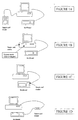
- Figure 1A shows the present solution where the reader requires an extra keyboard.
- Figure 1B shows the configuration where the reader is in the PC, and the PC has a LED for signaling a security operation being actually performed.
- Figure 1C shows the smart card reader integrated in the keyboard.
- Figure 1D has a separate smart card reader. None of the solutions of the Figures 1B-1D needs an additional keyboard; all of these configurations will be rendered secure through the teachings of the invention.
- Next to the display of the single bit in Figure 1B it is possible to display as a representation of the PIN code digits being entered, a string of dummy digits such as asterisks on the display for signaling the progress of the entering.
- actual screen display of digital data pertaining to the security operations, not being the PIN code may be judged advantageous for enhancing user trust.
- the indicator means may be joined to the controller housing, such as shown actually in Figure 1D.
- Various elements of the configurations shown, such as separate keyboard, PC, smart card reader, or semiconductor product may actually embody the invention as disclosed and claimed, for separate commercial exploitation.
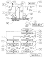
- Figure 5 presents an embodiment of the invention detailed on a wires-and-gates level. For simplicity, only one physical wire and associated circuitry has been shown. A full implementation needs one clock wire, as well as one data wire, that may have identical circuitry as the one shown. The solution may have a handshake implemented between the keyboard and Super I/O controllers. A software solution would be complex, but the configuration as shown causes no operating problems if the smart card is not active, so that a high level of compatibility is effected.
- the PC 60 at left comprises output buffer 64 and input buffer 66, line 68 being connected by pull-up resistor 62 to an appropriate voltage level.
- the secure hardware has been realized in a TDA8006 Microcontroller from Philips Electronics, of which the general purpose I/O driver has been symbolized by block 82.
- the microcontroller is housed in an appropriate package that can also contain a conventional berth, such as a slit, for entering a smart card.
- items 74, 76 represent a bidirectional buffer stage.
- items 78, 80 represent a bidirectional buffer stage that attaches to line 70. The latter attaches in keyboard 90 via bidirectional buffer pair 86, 88.
- Left and right wire parts 68, 70 have been separated by gate 72 that can be a FET-based switch of known design. Control is through line 94 driven by hardware 82.
- the set-up can be simplified if processing speed in controller 82 is large enough: this would allow to do away with switch 72 and have controller 82 take up to internally interrupt the line: for standard communication, the controller then operates as a transparent bidirectional buffer, while still monitoring for any forthcoming smart card operation.
- buffer 78 in many cases may be omitted due to the low load represented by keyboard 90, in combination with transport speed used. Redesign of the controller with larger internal buffers can make most of the external buffers superfluous.
- LED 92 that signals when certain secrecy-related procedures are being executed in microcontroller 82. This is one of various user-interface-related features that lets a user person appreciate the actual running of secrecy-related processes.
- a higher-level solution is to provide a multi-digit display to signal various transaction parameters such as money amounts.
- the additional controller IC maybe located in the PC, in the keyboard, or as add-on hardware such as shown in Figure 5. This would upgrade an existing combination, such as one that up to now was not used for performing the kind of secret operations described.
- the invention can be packaged in a WEB TV set or in a so-called set top box that is an extension facility to certain standard TV sets.
- FIG. 6 is a flow chart pertaining to the operation of the invention.
- block 100 the process is started and the necessary hardware and software facilities are claimed.
- block 102 the standard handshaking is operated, which is irrelevant to the present invention and will not be detailed further hereinafter.
- block 104 the signalizing for a forthcoming security operation is detected, such as a specific initial control signal. As long as the outcome is negative, loop 102/104 is continually traversed. When the detection is positive then an interrupt is activated in block 106, when a security operation between the smart card controller and the keyboard is detected to be forthcoming, respectively in block 114, when a security operation between the smart card controller and the PC is detected to be forthcoming.
- the handshaking will be interrupted, and the associated transfer stopped, because the smart card controller can now determine the operations on the physical link.
- the logical link for the security operations can be activated on the same physical link, and the security operations proper executed in block 108, respectively block 116.
- these operations can be conventional.
- a "ready" situation is awaited in block 110, respectively block 118, through a specific code, through a predetermined time lapse, or otherwise.
- the loop 108/110 respectively the loop 116/118, prevails.
- the system clears the interrupt in block 112, respectively block 120, and goes back to block 102.
- the overall stopping of the flow diagram has not been detailed herein.
- the invention may also be used for security operations between the smart card controller and the keyboard only, i.e. without executing blocks 114-120 in the flowchart.
Landscapes
- Engineering & Computer Science (AREA)
- Computer Hardware Design (AREA)
- Theoretical Computer Science (AREA)
- Computer Security & Cryptography (AREA)
- Software Systems (AREA)
- Physics & Mathematics (AREA)
- General Engineering & Computer Science (AREA)
- General Physics & Mathematics (AREA)
- Input From Keyboards Or The Like (AREA)
Priority Applications (3)
| Application Number | Priority Date | Filing Date | Title |
|---|---|---|---|
| EP99200433A EP0990971A1 (fr) | 1998-09-30 | 1999-02-16 | Configuration d'un ordinateur pour interfacer à un suppport de données sécurisé |
| PCT/EP1999/007392 WO2000019298A1 (fr) | 1998-09-30 | 1999-09-23 | Configuration informatique assurant l'interface avec un corps de donnees protegees |
| EP99948937A EP1118054A1 (fr) | 1998-09-30 | 1999-09-23 | Configuration informatique assurant l'interface avec un corps de donnees protegees |
Applications Claiming Priority (5)
| Application Number | Priority Date | Filing Date | Title |
|---|---|---|---|
| EP98203317 | 1998-09-30 | ||
| EP98203317 | 1998-09-30 | ||
| EP99200131 | 1999-01-19 | ||
| EP99200131 | 1999-01-19 | ||
| EP99200433A EP0990971A1 (fr) | 1998-09-30 | 1999-02-16 | Configuration d'un ordinateur pour interfacer à un suppport de données sécurisé |
Publications (1)
| Publication Number | Publication Date |
|---|---|
| EP0990971A1 true EP0990971A1 (fr) | 2000-04-05 |
Family
ID=27239403
Family Applications (2)
| Application Number | Title | Priority Date | Filing Date |
|---|---|---|---|
| EP99200433A Withdrawn EP0990971A1 (fr) | 1998-09-30 | 1999-02-16 | Configuration d'un ordinateur pour interfacer à un suppport de données sécurisé |
| EP99948937A Withdrawn EP1118054A1 (fr) | 1998-09-30 | 1999-09-23 | Configuration informatique assurant l'interface avec un corps de donnees protegees |
Family Applications After (1)
| Application Number | Title | Priority Date | Filing Date |
|---|---|---|---|
| EP99948937A Withdrawn EP1118054A1 (fr) | 1998-09-30 | 1999-09-23 | Configuration informatique assurant l'interface avec un corps de donnees protegees |
Country Status (2)
| Country | Link |
|---|---|
| EP (2) | EP0990971A1 (fr) |
| WO (1) | WO2000019298A1 (fr) |
Cited By (3)
| Publication number | Priority date | Publication date | Assignee | Title |
|---|---|---|---|---|
| WO2004072833A3 (fr) * | 2003-02-13 | 2005-02-03 | Koninkl Philips Electronics Nv | Dispositif de carte a puce securise |
| EP1980983A1 (fr) * | 2007-04-12 | 2008-10-15 | Siemens Schweiz AG | Procédé de communication pour transactions en ligne et appareil de communication correspondant |
| EP2738707A1 (fr) * | 2012-11-29 | 2014-06-04 | HID Global GmbH | Commande de lecture interactive |
Citations (6)
| Publication number | Priority date | Publication date | Assignee | Title |
|---|---|---|---|---|
| US4847867A (en) * | 1986-09-01 | 1989-07-11 | Nec Corporation | Serial bus interface system for data communication using two-wire line as clock bus and data bus |
| GB2267986A (en) * | 1992-09-04 | 1993-12-22 | Algorithmic Res Ltd | Security device for a computer. |
| CA2078020A1 (fr) * | 1992-09-11 | 1994-03-12 | Rodney G. Denno | Clavier et terminal connexes |
| US5517569A (en) * | 1994-03-18 | 1996-05-14 | Clark; Dereck B. | Methods and apparatus for interfacing an encryption module with a personal computer |
| FR2731812A1 (fr) * | 1995-03-14 | 1996-09-20 | Samsung Electronics Co Ltd | Ordinateur personnel avec carte a puce pour une interdiction d'utilisation non autorisee |
| US5742756A (en) * | 1996-02-12 | 1998-04-21 | Microsoft Corporation | System and method of using smart cards to perform security-critical operations requiring user authorization |
-
1999
- 1999-02-16 EP EP99200433A patent/EP0990971A1/fr not_active Withdrawn
- 1999-09-23 WO PCT/EP1999/007392 patent/WO2000019298A1/fr not_active Ceased
- 1999-09-23 EP EP99948937A patent/EP1118054A1/fr not_active Withdrawn
Patent Citations (6)
| Publication number | Priority date | Publication date | Assignee | Title |
|---|---|---|---|---|
| US4847867A (en) * | 1986-09-01 | 1989-07-11 | Nec Corporation | Serial bus interface system for data communication using two-wire line as clock bus and data bus |
| GB2267986A (en) * | 1992-09-04 | 1993-12-22 | Algorithmic Res Ltd | Security device for a computer. |
| CA2078020A1 (fr) * | 1992-09-11 | 1994-03-12 | Rodney G. Denno | Clavier et terminal connexes |
| US5517569A (en) * | 1994-03-18 | 1996-05-14 | Clark; Dereck B. | Methods and apparatus for interfacing an encryption module with a personal computer |
| FR2731812A1 (fr) * | 1995-03-14 | 1996-09-20 | Samsung Electronics Co Ltd | Ordinateur personnel avec carte a puce pour une interdiction d'utilisation non autorisee |
| US5742756A (en) * | 1996-02-12 | 1998-04-21 | Microsoft Corporation | System and method of using smart cards to perform security-critical operations requiring user authorization |
Cited By (4)
| Publication number | Priority date | Publication date | Assignee | Title |
|---|---|---|---|---|
| WO2004072833A3 (fr) * | 2003-02-13 | 2005-02-03 | Koninkl Philips Electronics Nv | Dispositif de carte a puce securise |
| EP1980983A1 (fr) * | 2007-04-12 | 2008-10-15 | Siemens Schweiz AG | Procédé de communication pour transactions en ligne et appareil de communication correspondant |
| EP2738707A1 (fr) * | 2012-11-29 | 2014-06-04 | HID Global GmbH | Commande de lecture interactive |
| US9111401B2 (en) | 2012-11-29 | 2015-08-18 | Hid Global Gmbh | Interactive reader commander |
Also Published As
| Publication number | Publication date |
|---|---|
| EP1118054A1 (fr) | 2001-07-25 |
| WO2000019298A1 (fr) | 2000-04-06 |
Similar Documents
| Publication | Publication Date | Title |
|---|---|---|
| KR100285111B1 (ko) | 카드 인터페이스 | |
| CA2182783C (fr) | Systeme d'echange de donnees comportant des unites portatives de traitement de donnees | |
| US6945454B2 (en) | Smart card device used as mass storage device | |
| EP1457901A2 (fr) | Système et procédé pour la simulation de cartes à puce USB connexes avec USB-hote | |
| EP2809054A1 (fr) | Dispositif électronique mobile doté d'un émetteur-récepteur pour échanger des données sans fil | |
| CN101120354B (zh) | 用于操作装置的装置和方法 | |
| CN1365484A (zh) | 集成外围设备的智能卡结构 | |
| US7823133B2 (en) | Smart card device and method for debug and software development | |
| US8719840B2 (en) | Device for secure interprocess communication | |
| US7328849B2 (en) | Smart card providing data mapping for multiple applications and related methods | |
| US7942325B2 (en) | Optimized smart card driver performance | |
| US6769620B2 (en) | IC card reader with improved man-machined interface | |
| US7831837B1 (en) | Encoding token commands/data within data streams for standard interfaces | |
| US7904607B2 (en) | Smart card with self-reconfiguration features and related methods | |
| KR100426302B1 (ko) | 범용 직렬 버스 인터페이스 기능이 포함된 스마트 카드 | |
| WO2000019298A1 (fr) | Configuration informatique assurant l'interface avec un corps de donnees protegees | |
| KR100411584B1 (ko) | 접촉식 및 비접촉식 스마트카드를 지원하는 카드 단말기와그 제어방법 | |
| US6866192B2 (en) | IC card terminal | |
| US20030150913A1 (en) | IC card terminal | |
| JP2003203056A (ja) | ユーザクライアントサーバシステム | |
| US7757031B2 (en) | Data transmission coordinating method and system | |
| US20030149877A1 (en) | Smart card with keypro function | |
| CN114422989A (zh) | 智能终端内的nfc通信装置及方法 | |
| US20030217298A1 (en) | Method of a saving power mode by combining a smart card with a multi-function network card | |
| EP1385080A1 (fr) | Dispositif comportant un lecteur de cartes et un réseau et procédé correspondant pour économiser l'énergie |
Legal Events
| Date | Code | Title | Description |
|---|---|---|---|
| PUAI | Public reference made under article 153(3) epc to a published international application that has entered the european phase |
Free format text: ORIGINAL CODE: 0009012 |
|
| AK | Designated contracting states |
Kind code of ref document: A1 Designated state(s): AT BE CH CY DE DK ES FI FR GB GR IE IT LI LU MC NL PT SE |
|
| AX | Request for extension of the european patent |
Free format text: AL;LT;LV;MK;RO;SI |
|
| AKX | Designation fees paid | ||
| STAA | Information on the status of an ep patent application or granted ep patent |
Free format text: STATUS: THE APPLICATION IS DEEMED TO BE WITHDRAWN |
|
| 18D | Application deemed to be withdrawn |
Effective date: 20001006 |
|
| REG | Reference to a national code |
Ref country code: DE Ref legal event code: 8566 |