EP0990975B1 - Appareil de traitement d'information et méchanisme d'accrochage applicable à l'appareil - Google Patents
Appareil de traitement d'information et méchanisme d'accrochage applicable à l'appareil Download PDFInfo
- Publication number
- EP0990975B1 EP0990975B1 EP98301495A EP98301495A EP0990975B1 EP 0990975 B1 EP0990975 B1 EP 0990975B1 EP 98301495 A EP98301495 A EP 98301495A EP 98301495 A EP98301495 A EP 98301495A EP 0990975 B1 EP0990975 B1 EP 0990975B1
- Authority
- EP
- European Patent Office
- Prior art keywords
- face
- condition
- slider
- pawl
- hook
- Prior art date
- Legal status (The legal status is an assumption and is not a legal conclusion. Google has not performed a legal analysis and makes no representation as to the accuracy of the status listed.)
- Expired - Lifetime
Links
Images






Classifications
-
- G—PHYSICS
- G06—COMPUTING OR CALCULATING; COUNTING
- G06F—ELECTRIC DIGITAL DATA PROCESSING
- G06F1/00—Details not covered by groups G06F3/00 - G06F13/00 and G06F21/00
- G06F1/16—Constructional details or arrangements
- G06F1/1613—Constructional details or arrangements for portable computers
- G06F1/1615—Constructional details or arrangements for portable computers with several enclosures having relative motions, each enclosure supporting at least one I/O or computing function
- G06F1/1616—Constructional details or arrangements for portable computers with several enclosures having relative motions, each enclosure supporting at least one I/O or computing function with folding flat displays, e.g. laptop computers or notebooks having a clamshell configuration, with body parts pivoting to an open position around an axis parallel to the plane they define in closed position
- G06F1/1618—Constructional details or arrangements for portable computers with several enclosures having relative motions, each enclosure supporting at least one I/O or computing function with folding flat displays, e.g. laptop computers or notebooks having a clamshell configuration, with body parts pivoting to an open position around an axis parallel to the plane they define in closed position the display being foldable up to the back of the other housing with a single degree of freedom, e.g. by 360° rotation over the axis defined by the rear edge of the base enclosure
-
- E—FIXED CONSTRUCTIONS
- E05—LOCKS; KEYS; WINDOW OR DOOR FITTINGS; SAFES
- E05B—LOCKS; ACCESSORIES THEREFOR; HANDCUFFS
- E05B63/00—Locks or fastenings with special structural characteristics
- E05B63/14—Arrangement of several locks or locks with several bolts, e.g. arranged one behind the other
-
- G—PHYSICS
- G06—COMPUTING OR CALCULATING; COUNTING
- G06F—ELECTRIC DIGITAL DATA PROCESSING
- G06F1/00—Details not covered by groups G06F3/00 - G06F13/00 and G06F21/00
- G06F1/16—Constructional details or arrangements
- G06F1/1613—Constructional details or arrangements for portable computers
- G06F1/1615—Constructional details or arrangements for portable computers with several enclosures having relative motions, each enclosure supporting at least one I/O or computing function
- G06F1/1616—Constructional details or arrangements for portable computers with several enclosures having relative motions, each enclosure supporting at least one I/O or computing function with folding flat displays, e.g. laptop computers or notebooks having a clamshell configuration, with body parts pivoting to an open position around an axis parallel to the plane they define in closed position
- G06F1/162—Constructional details or arrangements for portable computers with several enclosures having relative motions, each enclosure supporting at least one I/O or computing function with folding flat displays, e.g. laptop computers or notebooks having a clamshell configuration, with body parts pivoting to an open position around an axis parallel to the plane they define in closed position changing, e.g. reversing, the face orientation of the screen with a two degrees of freedom mechanism, e.g. for folding into tablet PC like position or orienting towards the direction opposite to the user to show to a second user
-
- G—PHYSICS
- G06—COMPUTING OR CALCULATING; COUNTING
- G06F—ELECTRIC DIGITAL DATA PROCESSING
- G06F1/00—Details not covered by groups G06F3/00 - G06F13/00 and G06F21/00
- G06F1/16—Constructional details or arrangements
- G06F1/1613—Constructional details or arrangements for portable computers
- G06F1/1633—Constructional details or arrangements of portable computers not specific to the type of enclosures covered by groups G06F1/1615 - G06F1/1626
- G06F1/1675—Miscellaneous details related to the relative movement between the different enclosures or enclosure parts
- G06F1/1679—Miscellaneous details related to the relative movement between the different enclosures or enclosure parts for locking or maintaining the movable parts of the enclosure in a fixed position, e.g. latching mechanism at the edge of the display in a laptop or for the screen protective cover of a PDA
-
- E—FIXED CONSTRUCTIONS
- E05—LOCKS; KEYS; WINDOW OR DOOR FITTINGS; SAFES
- E05B—LOCKS; ACCESSORIES THEREFOR; HANDCUFFS
- E05B63/00—Locks or fastenings with special structural characteristics
- E05B63/0065—Operating modes; Transformable to different operating modes
-
- E—FIXED CONSTRUCTIONS
- E05—LOCKS; KEYS; WINDOW OR DOOR FITTINGS; SAFES
- E05C—BOLTS OR FASTENING DEVICES FOR WINGS, SPECIALLY FOR DOORS OR WINDOWS
- E05C1/00—Fastening devices with bolts moving rectilinearly
- E05C1/08—Fastening devices with bolts moving rectilinearly with latching action
-
- E—FIXED CONSTRUCTIONS
- E05—LOCKS; KEYS; WINDOW OR DOOR FITTINGS; SAFES
- E05C—BOLTS OR FASTENING DEVICES FOR WINGS, SPECIALLY FOR DOORS OR WINDOWS
- E05C5/00—Fastening devices with bolts moving otherwise than only rectilinearly and only pivotally or rotatively
Definitions
- This invention relates to an information processing apparatus and a hook mechanism applicable to the apparatus.
- an apparatus which includes a first member (for example, a cover having a display unit), a second member (for example, an apparatus body having a keyboard unit), and a connection member for connecting the first and second members to each other.
- a condition wherein the first member is closed with respect to the second member is suitable for protection of the keyboard unit and the display unit when the apparatus is carried, but another condition wherein the first member is open with respect to the second member is suitable for use of the apparatus using the keyboard unit and/or the display unit.
- a hook mechanism As a conventional simple hook mechanism which can be applied to such an apparatus as described above, a hook mechanism is known wherein a displaceable hook member is provided on one of the first and second members while a hole for being engaged by the hook member is formed in the other of the first and second members. Since the hook member is engaged, in a condition wherein the first member is closed with respect to the second member, with the hole to keep the closed condition, transportation of the apparatus is facilitated. On the other hand, if the engagement of the hook member with the hole is released, then the first member can be opened with respect to the second member.
- a stylus stylus pen
- a transparent touch panel is provided on the surface of a display unit (or a LCD) such that the stylus is touched at an end thereof with the touch panel to effect inputting or assist inputting by a keyboard.
- a touch panel which uses an electromagnetic induction digitizer detecting a magnetic field from the stylus pen. This electromagnetic induction digitizer is located under the LCD, the stylus pen generates magnetism when the stylus touches the LCD, and the electromagnetic induction digitizer detects this magnetism to point or input to the display thereby.
- the first member having the display unit When only the stylus is used to perform an inputting operation, if the first member having the display unit is open with respect to the second member, then the inputting operation cannot always be performed readily. Therefore, it is convenient if, where the first member has a first face and a second face and the display unit is provided on the first face, a first condition wherein the first face opposes the second member and a second condition wherein the second face opposes the second member are available.
- the first member since the first member is closed with respect to the second member in both of the first and second conditions and, in the second condition, the display unit is directed outwardly of the apparatus, an inputting operation using the touch panel and the stylus can be performed readily.
- connection member for connecting the first and second members to each other may be improved.
- the improved connection member includes two axes extending in parallel to each other for individually supporting the first member for pivotal motion or two axes extending perpendicularly to each other for individually supporting the first member for pivotal motion.
- connection member as just described and a conventional simple hook mechanism described above are combined, then since the hook mechanism can keep the closed condition only in one of the first and second conditions, the operability is deteriorated in that an inputting operation using the stylus cannot be performed readily and so forth.
- EP-A-0600410 discloses an apparatus and a hook mechanism according to the preamble of claim 1.
- a first member (display unit) has a connector on its base which is capable of being plugged either way round into a socket provided on a second member (apparatus body).
- the connector is pulled out of the socket thus separating the two members, and the first member is turned through 180° allowing the connector to be plugged into the socket the other way round.
- EP-A-0454120 discloses an apparatus according to the preamble of accompanying claim 10.
- a first member (upper case) is connected to a second member (main body case) via a double hinge arrangement, in which a first hinge allows the first member to rotate by 180°, and the second hinge is disposed in an arcuate groove running around one end of the second member.
- the first member is slid around the end of the first member using the second hinge and then folded flat using the first hinge.
- An embodiment of the present invention may provide an information processing apparatus of a simple construction which includes two members by which two different closed conditions can be kept.
- An embodiment of the present invention may also provide a hook mechanism which can be applied to such an apparatus as just described.
- an information processing apparatus which comprises a first member, a second member, and a connection member or unit.
- the first member has a first face and a second face.
- the connection member connects the first and second members to each other such that the first and second members are displaceable relative to each other between a first condition wherein the first face of the first member opposes the second member and a second condition wherein the second face of the first member opposes the second member.
- the first member has a hook member provided thereon such that the hook member can be selectively projected from one of the first and second faces.
- the second member has a hole for being engaged by the hook member.
- the second member has a third face and a fourth face and the hole is provided in each of the third and fourth faces
- the connection member includes two axes extending parallel to each other for individually supporting the first member for pivotal motion.
- Such a connection member as just described can be constructed simply as hereinafter described in detail. In the first condition, the hook member is engaged with the hole of the third face with the first face and the third face opposed to each other, but in the second condition, the hook member is engaged with the hole of the fourth face with the second face and the fourth face opposed to each other.
- a display unit is provided on the first face of the first member and a keyboard unit is provided on the third face of the second member, then, in the first condition, the display unit and the keyboard unit are confined between the first and second members, but in the second condition, the display unit and the keyboard unit are directed outwardly of the information processing apparatus.
- the second member has a third face and a fourth face and the hole is provided in the third face
- the connection member includes two axes extending perpendicularly to each other for individually supporting the first member for pivotal motion. Then, in the first condition, the hook member is engaged with the hole with the first face and the third face opposed to each other, but in the second condition, the hook member is engaged with the hole with the second face and the third face opposed to each other.
- a display unit is provided on the first face of the first member and a keyboard unit is provided on the third face of the second member, then, in the first condition, the display unit and the keyboard unit are confined between the first and second members, but in the second condition, the display unit is directed outwardly of the information processing apparatus and the keyboard unit is confined between the first and second members.
- a hook mechanism comprising a housing having a first face and a second face, a slider mounted for sliding movement in the housing, a hook member mounted for pivotal motion within a range of approximately 90 degrees with respect to the slider, and a spring for biasing the hook member in its pivoting direction.
- the hook member has a first pawl and a second pawl disposed substantially perpendicularly to each other. The first pawl is positioned in the housing when the second pawl projects from the second face whereas, when the first pawl projects from the first face, the second pawl is positioned in the housing.
- an information processing apparatus comprising a first member having a first face and a second face, a second member, a connection member or unit for connecting the first and second members to each other such that the first and second members are displaceable relative to each other between a first condition wherein the first face of the first member opposes the second member and a second condition wherein the second face of the first member opposes the second member, and a slider mounted for sliding movement between a position in which the slider holds the first and second members in-between and another position in which the slider does not hold the first and second members in-between in each of the first and second conditions.
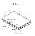
- the apparatus body 2 includes an upper housing 8 and a lower housing 10 for providing an upper face 2A and a lower face 2B of the apparatus body 2, respectively.
- a keyboard unit 12 to be used for inputting of data and so forth is provided on the upper housing 8.
- the apparatus body 2 has the keyboard unit 12 on the upper face 2A thereof.
- the cover 4 includes an upper housing 14 and a lower housing 16 for providing an upper face 4A and a lower face 4B of the cover 4, respectively.
- a display unit 18 to be used for displaying and for stylus inputting is provided on the lower housing 16 of the cover 4.
- the cover 4 has the display unit 18 on the lower face 4B thereof.
- the display unit 18 includes, for example, an LCD (liquid crystal display) panel and a transparent touch panel provided on the LCD panel.
- there is another type of touch panel which uses an electromagnetic induction digitizer detecting magnetic from the stylus pen. This electromagnetic induction digitizer is located under the LCD, the stylus pen generates magnetism when the stylus touches the LCD, and the electromagnetic induction digitizer detects this magnetism to point or input to the display thereby.
- the cover 4 has a hook mechanism 20.
- Each of the apparatus body 2 and the cover 4 is in the form of a generally quadrangular flat plate, and the hook mechanism 20 is positioned along an edge of the cover 4 remote from the connection member 6. The reason why the position of the hook mechanism 20 is set in this manner is that it is intended to suppress the force which may act upon the hook mechanism 20 in order to keep the condition wherein the cover 4 is closed with respect to the apparatus body 2 to the minimum. Details of a construction and operation of the hook mechanism 20 will be hereinafter described.
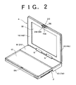
- connection member 6 can be constructed simply such that it has two axes 22 and 24 extending parallel to each other for each supporting the cover 4 for pivotal motion with respect to the apparatus body 2. More particularly, the connection member 6 is supported for pivotal motion within a range of approximately 180 degrees with respect to the apparatus body 2 by the axis 22, and the cover 4 is supported for pivotal motion within a range of approximately 180 degrees with respect to the connection member 6 by the axis 24. As a result, the cover 4 is supported for pivotal motion within a range of 360 degrees with respect to the apparatus body 2.
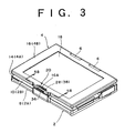
- the apparatus body 2 and the cover 4 can be displaced relative to each other between a first condition wherein the cover 4 is closed with respect to the apparatus body 2 with the lower face 4B of the cover 4 opposed to the apparatus body 2 as seen in FIG. 1 and a second condition wherein the cover 4 is closed with respect to the apparatus body 2 with the upper face 4A of the cover 4 opposed to the apparatus body 2 as seen in FIG. 3 .
- the keyboard unit 12 and the display unit 18 are directed outwardly of the apparatus, if the apparatus is held in hand or placed on a desk with the apparatus body 2 positioned downwardly, for example, then the display unit 18 is directed upwardly, and inputting using the stylus can be performed readily while the display unit 18 is observed.
- the cover 4 and the apparatus body 2 can be kept in a condition wherein the cover 4 is open with respect to the apparatus body 2 as seen in FIG. 2 between the first and second conditions, an inputting operation using the keyboard unit 12 can be performed while the display unit 18 is observed.
- An inputting operation using the stylus can be performed using the display unit 18 in the condition shown in FIG. 2 .
- the apparatus may be used in such a condition that the keyboard unit 12 and the display unit 18 are directed upwardly by pivoting the cover 4 by approximately 180 degrees from the condition shown in FIG. 1 .
- FIGS. 5A and 5B are sectional views showing a first embodiment of the hook mechanism
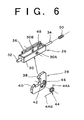
- FIG. 6 is a fragmentary perspective view showing a principal portion of the first embodiment of the hook mechanism. More particularly, in FIG. 5A , a section of the hook mechanism 20 taken along line 5A-5A of FIG. 1 is shown, and in FIG. 5B , a section of the hook mechanism 20 taken along line 5B-5B of FIG. 3 is shown. Further, in FIG. 6 , a principal portion of the hook mechanism 20 is shown.
- the hook mechanism 20 includes a slider 26, and a hook member 28 mounted for pivotal motion within a range of approximately 90 degrees on the slider 26.
- the slider 26 has a frame 30 in the form of a box which is open at the top and the bottom thereof, and a comparatively short sliding shaft 32 and a comparatively long sliding shaft 34 which project in the opposite directions to each other from the longitudinal opposite ends of the frame 30.
- a slide button 36 is provided on one side portion of the frame 30.
- the hook member 28 has a first pawl 38 and a second pawl 40 disposed substantially in a perpendicular relationship to each other.
- the pawls 38 and 40 substantially have a relationship of a mirror image relative to each other.
- the hook member 28 further has a shaft 42 which provides the center of pivotal motion of the hook member 28, and a projection 46 formed in the proximity of the shaft 42.
- a spring 44 is mounted on one side of the hook member 28 such that it surrounds the shaft 42, and the opposite ends of the shaft 42 are inserted in a pair of holes 30A and 30B formed in the frame 30 to mount the hook member 28 on the slider 26.
- a stopper 48 for limiting the range of pivotal motion of the hook member 28 approximately to 90 degrees is formed on an inner side of the frame 30.
- One end 44A of the spring 44 is held in contact with the projection 46 of the hook member 28 while the other end 44B of the spring 44 is held in contact with a shoulder not shown formed on the inner side of the frame 30.
- the spring 44 biases, by a resilient restoring force tending to increase the angle defined between the one end 44A and the other end 44B thereof, the hook member 28 in a direction to contact the back of the first pawl 38 with the stopper 48.
- a coil spring 50 is mounted on the comparatively long sliding shaft 34.
- two slider receiving portions 52 and 54 which extend into the cover 4 are formed on the lower housing 16 of the cover 4.
- the sliding shafts 32 and 34 of the slider 26 are supported for sliding movement by the slider receiving portions 52 and 54, respectively. Accordingly, the slider 26 can be slidably moved in the cover 4.
- the coil spring 50 is interposed between the slider receiving portion 54 and the frame 30 of the slider 26, and accordingly, the coil spring 50 biases the slider 26 in a direction from the slider receiving portion 54 toward the slider receiving portion 52.
- the upper housing 14 of the cover 4 has an opening 14A so as allow the second pawl 40 of the hook member 28 to project upwardly from the upper face 4A of the cover 4.
- the lower housing 16 of the cover 4 has an opening 16A so as to allow the first pawl 38 of the hook member 28 to project downwardly from the lower face 4B of the cover 4.
- a portion of the lower housing 16 around the opening 16A is smoothly curved downwards so that a predetermined distance may be provided between the apparatus body 2 and the cover 4 in the first condition.
- the upper housing 8 of the apparatus body 2 has a hole 8A with which the first pawl 38 of the hook member 28 is to engage.
- the lower housing 10 of the apparatus body 2 has a hole 10A with which the second pawl 40 of the hook member 28 is to engage.
- the slide button 36 is directed outwardly of the cover 4 as seen, for example, in FIG. 1 .
- the slide button 36 is connected to the slider 26 on the inner side of the cover 4 through an opening not shown formed in the cover 4. Accordingly, by moving the slide button 36, the slider 26 can be moved from the left toward the right in FIG. 5A against the biasing force of the coil spring 50.
- the slider 26 When it is intended to change over the condition of the apparatus from the condition shown in FIG. 1 to the condition shown in FIG. 2 , the slider 26 is slidably moved using the slide button 36 to contract the coil spring 50. Consequently, the engagement of the first pawl 38 with the hole 8A is cancelled, and the first pawl 38 can pass in the hole 8A.
- the hook mechanism 20 when the condition of the apparatus is changed over from the condition shown in FIG. 2 to the second condition shown in FIG. 3 is described.
- the back of the first pawl 38 is held in contact with the stopper 48 by the biasing force of the spring 44 and the hook member 28 is in a stable condition. If a force acting against the biasing force of the spring 44 is applied to the first pawl 38 by a finger, then the hook member 28 can be pivoted until the back of the second pawl 40 is brought into contact with the stopper 48. In particular, the hook member 28 is pivoted by 90 degrees clockwise from the condition shown in FIG. 5A .
- the first pawl 38 is positioned in the cover 4 and the second pawl 40 projects upwardly from the upper face 4A of the cover 4 through the opening 14A. Accordingly, if the cover 4 is closed toward the second condition shown in FIG. 3 with respect to the apparatus body 2 while keeping the condition described above in a manner wherein the opening 16A is closed up with a finger, then the second pawl 40 can be engaged with the hole 10A of the lower housing 10 of the apparatus body 2 as seen in FIG. 5B in a similar manner as in the case wherein the first condition is reached. Accordingly, the second condition shown in FIG. 3 can be kept by the hook mechanism 20.
- the slide button 36 When it is intended to change over the condition of the apparatus from the second condition shown in FIG. 3 to the condition shown in FIG. 2 , the slide button 36 is moved to slidably move the slider 26 to contract the coil spring 50.
- the cover 4 when the cover 4 is moved away from the apparatus body 2, the biasing force of the spring 44 is released, and consequently, the hook member 28 is automatically pivoted by 90 degrees so that the stable condition shown in FIG. 2 is restored.
- the reason why the spring 44 is used in the present embodiment to stabilize the hook member 28 as seen in FIG. 2 is that normally the operation for closing the cover 4 from the condition shown in FIG. 2 toward the first condition shown in FIG. 1 is performed much more frequently than the operation for closing the cover 4 from the condition shown in FIG. 2 toward the second condition shown in FIG. 3 and such a stable position of the hook member 28 as shown in FIG. 2 is more advantageous for the former operation.
- the hook member 28 since the hook member 28 has the first pawl 38 and the second pawl 40 so that the hook member 28 can selectively project from any one of the upper face 4A and the lower face 4B of the cover 4, in whichever one of the first and second conditions the apparatus is, the hook member 28 does not come out of the apparatus by operating the hook mechanism 20 in each of the first and second conditions. Consequently, operability of the apparatus is improved and the appearance of the apparatus is improved.
- the apparatus is simplified in construction compared with an alternative apparatus which uses two such conventional simple hook mechanisms as described above.
- the hook member 28 can be returned automatically to such a position at which the hook member 28 should stand by as seen in FIG. 2 . Consequently, the operability is improved and the safety is improved.
- FIGS. 7A and 7B are perspective views showing another embodiment of the information processing apparatus according to the present invention.
- Reference numeral 111 denotes an apparatus body, and the apparatus body 111 has a keyboard unit 112 for performing an inputting operation.
- Reference numeral 113 denotes a cover, and the cover 113 is formed as a plate of a generally rectangular shape and supported for opening and closing movement on the apparatus body 111 by a horizontal first axis 114.
- the cover 113 includes a display unit 115 on a face (front surface) thereof which opposes the keyboard unit 112 in a condition wherein it is closed around the first axis 114.
- the cover 113 is supported for pivotal motion by approximately 180 degrees around a second axis 116 substantially perpendicular to the first axis 114 in a condition wherein it is open around the first axis 114 in such a manner that the front surface and the rear surface are replaced with each other as seen in FIG. 7B .
- the cover 113 By closing the cover 113 around the first axis 114 in a condition wherein the cover 113 is reversed around the second axis 116, the cover 113 is positioned on the keyboard unit 112 with the display unit 115 directed upwardly as seen in FIG. 7B .
- the cover 113 is closed in such a manner that the display unit 115 opposes the keyboard unit 112 so that the display unit 115 and the keyboard unit 112 are protected by the cover 113.
- the cover 113 When the present apparatus is used to perform inputting operation using the keyboard unit 112 and the stylus, the cover 113 is put into an open condition around the first axis 114 as seen in FIG. 7A . When an inputting operation is to be performed using only the stylus, the cover 113 is reversed around the second axis 116 from the open condition and then it is put into a closed condition around the first axis 114 as seen in FIG. 7B .
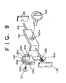
- the present apparatus adopts such a second embodiment of the hook mechanism as shown in FIGS. 8A, 8B and 9 in order to keep the closed condition of the cover 113 with respect to the apparatus body 111 from the point of view of transportation and so forth.
- Two holes 118 each in the form of an elongated through-hole of a substantially rectangular shape are formed in a housing 117 of the apparatus body 111 on the opposite sides of the keyboard unit 112. Meanwhile, two holes 120 each in the form of an elongated through-hole of a rectangular shape are formed in a housing 119 of the cover 113 on the opposite sides of the display unit 115 corresponding to the holes 118.
- Two holes 121 each in the form of an elongated through-hole of a substantially rectangular shape are formed at positions on a face (rear face) 119b on the opposite side of a front face 119a of the housing 119 individually corresponding to the holes 118.
- Reference numeral 122 denotes a hook member having a pawl 122a for releasably engaging with a corresponding one of the holes 118.
- Each of the hook members 122 has resilient portions each having a protrusion 122b and a post-like projection 122c having a rectangular hole therein.
- Reference numeral 123 denotes a holder member (slider), and a shaft member 124 is integrally secured to the holder member 123.
- a pair of support members 125 are provided integrally in the proximity of positions of an inner face of the housing 119 corresponding to the holes 120 and 121.
- Each of the support members 125 has a through-hole formed therein, and the shaft member 124 is inserted in the through-holes of the support members 125 to support the holder member 123 for sliding movement.
- Each of the hook members 122 is mounted for pivotal motion on the corresponding holder member 123 by inserting, in a condition wherein the projection 122c of the hook member 122 is inserted in a through-hole 123a of the corresponding holder member 123, a knob member 126 from the outside into a through-hole formed in a side wall of the housing 119 and into the rectangular hole of the projection 122c of the hook member 122 and screwing a screw 127 into an end of the knob member 126 from the opposite side.
- Reference numeral 128 denotes a coil spring for biasing the hook member 122 so that the pawl 122a may be engaged with the corresponding hole 118. Further, the holder member 123 has a recess 123b formed thereon with which a protrusion 122b of the hook member 122 can be engaged. A pair of slits 122d are formed in the hook member 122 so that the protrusions 122b may be supported resiliently.
- each of the knob members 126 is turned until the pawl 122a of the hook member 122 passes through the hole 120 and projects from the front face 119a (face adjacent the display unit 115), and then the cover 113 is closed around the first axis 114 such that the display unit 115 may oppose the keyboard unit 112. Consequently, the pawl 122a of the hook member 122 is engaged with the hole 118 by the biasing force of the coil spring 128 and the cover 113 is put into a condition wherein it is closed with respect to the apparatus body 111.
- the knob member 126 When it is intended to open the cover 113 around the first axis 114, the knob member 126 is slidably moved against the biasing force of the coil spring 128 to cancel the engagement of the pawl 122a of the hook member 122 with the hole 118.
- the cover 113 is reversed around the second axis 116 from the open condition (condition of FIG. 7A ), and the knob member 126 is turned until the pawl 122a of the hook member 122 passes through the hole 121 and projects to the rear face 119b side.
- the knob member 126 When it is intended to open the cover 113 around the first axis 114, the knob member 126 is slidably moved against the biasing force of the coil spring 128 to cancel the engagement of the pawl 122a of the hook member 122 with the hole 118.
- the hook member 122 is resiliently engaged at one of the protrusions 122 thereof with the recess 123b of the holder member 123 in a condition wherein the pawl 122a projects from the hole 120 or the hole 121. Accordingly, positioning when the hook member 122 is pivoted is sure, and engagement of the pawl 122a with the hole 118 is performed with certainty.
- the cover 113 can be locked to the apparatus body 111 not only in a condition wherein the display unit 115 opposes the apparatus body 111 but also in another condition wherein the display unit 115 is directed upwardly, and in any of the two conditions, the information inputting apparatus can be carried without any trouble.
- the pawl 122a of the hook member 122 can be accommodated into the housing 119 by a turning operation of the hook member 122, and an obstacle to a manual operation caused by the pawl 122a of the hook member 122 when it is in a projecting condition is eliminated.
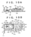
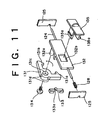
- FIGS. 10A and 10B there is shown a third embodiment of the hook mechanism.
- Reference numeral 131 denotes a hook member having a pair of pawls 131a and 131b which releasably engage with a hole 118 of the housing 117.
- the pawls 131a and 131b are disposed substantially in a perpendicular relationship to each other.
- the hook member 131 has a through-hole 131c at a central portion thereof, and further has a pair of recesses 131d.
- Reference numeral 132 denotes a holder member (slider), and the shaft member 124 is integrally secured to the holder member 132.
- the holder member 132 has a post-like projection 132a, a rectangular hole 132b, and a pair of spring mounting projections 132c.
- a spring 133 having a protrusion 133a is attached to the projections 132c.
- the hook member 131 is supported for pivotal motion on the holder member 132 as a screw 134 is screwed in an end of the projection 132a in a condition wherein the projection 132a of the holder member 132 is inserted in the through-hole 131c.
- Reference numeral 135 denotes a knob member, and the knob member 135 has a pair of engaging projections 135a.
- the engaging projections 135a are inserted from the outside in a through-hole 119c formed in a side wall of the housing 119 and further inserted in and engaged with the rectangular hole 132b of the holder member 132 to secure the knob member 135 to the holder member 132.
- Reference numeral 128 denotes a coil spring for biasing the hook member 131 so that the pawl 131a or 131b thereof may be engaged with the hole 118.
- the hook member 131 When the present information processing apparatus is not used, the hook member 131 is pivoted until the pawl 131a of the hook member 131 passes through the hole 120 and projects from the front face (face adjacent the display unit 115) 119a. Then, if the cover 113 is closed around the first axis 114 such that the display unit 115 may oppose the keyboard unit 112, then the pawl 131a of the hook member 131 is engaged with the hole 118 by the biasing force of the coil spring 128 and the cover 113 is put into a condition wherein it is closed with respect to the apparatus body 111.
- the knob member 135 When it is intended to open the cover 113 around the first axis 114, the knob member 135 is slidably moved against the biasing force of the coil spring 128 to cancel the engagement of the pawl 131a of the hook member 131 with the hole 118.
- the cover 113 is reversed around the second axis 116 from the open condition (condition of FIG. 7A ) and the hook member 131 is pivoted until the other pawl 131b of the hook member 131 passed through the hole 121 and projects to the rear face 119b side.
- the knob member 135 When it is intended to open the cover 113 around the first axis 114, the knob member 135 is slidably moved against the biasing force of the coil spring 128 to cancel the engagement of the pawl 131b of the hook member 131 with the hole 118.
- the protrusion 133a of the spring 133 is resiliently engaged with one of the recesses 131d of the hook member 131 in a condition wherein the one pawl 131a projects from the hole 120 or the other pawl 131b projects from the hole 121, positioning of the hook member 131 when it is pivoted is sure, and engagement of the pawl 131a or 131b with the hole 118 is performed with certainty.
- the cover 113 can be locked to the apparatus body 111 not only in a condition wherein the display unit 115 opposes the apparatus body 111 but also in another condition wherein the display unit 115 is directed upwardly, and in any of the two conditions, the information processing apparatus can be carried without any trouble.
- the pawl 131b of the hook member 131 can be accommodated into the housing 119 by a turning operation of the hook member 131, and also an obstacle to a manual operation caused by the pawl 131b of the hook member 131 when it is in a projecting condition is eliminated.
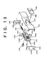
- FIGS. 12A and 12B as well as 13, there is shown a fourth embodiment of the hook mechanism.
- Reference numeral 141 denotes a hook member having a pair of pawls 141a and 141b which releasably engage with the hole 118 of the housing 117.
- the pawls 141a and 141b are formed such that they extend substantially in the opposite directions to each other.
- the hook member 141 has a through round hole 141c at a central body portion thereof.
- Reference numeral 142 denotes a holder member (slider), and the holder member 142 has a pair of rectangular frame members integrally secured thereto and has a pair of slits 142a formed at upper and lower portions thereof.
- a shaft member 143 is integrally secured to the holder member 142.
- An end portion 143a of the shaft member 143 has a tapering shape.
- a pair of support members 144 and 145 are provided in the proximity of positions of an inner face of the housing 119 corresponding to the holes 120 and 121.
- a pair of through-holes 144a and 144b are formed at upper and lower portions of the support member 144, respectively, and a slit 145a is formed in the support member 145.
- the shaft member 143 is inserted in one of the through-holes 144a and 144b and the slit 145a to support the holder member 142 for sliding movement.
- the hook member 141 is supported for sliding movement on the inner side of the holder member 142 as it is disposed such that a body portion of the hook member 141 is positioned on the inner side of the frame members of the holder member 142 and the pawls 141a and 141b extend through the slits 142a and project upwardly and downwardly, respectively.
- Reference numeral 146 denotes a coil spring, and the coil spring 146 biases the hook member 141 in a direction in which the pawl 141a or 141b is engaged with the hole 118 on the inner side of the holder member 142.
- a guideway 147 of a substantially U- or V-shape laid down horizontally as seen in FIGS. 12B and 13 is formed in a side wall of the housing 119.
- Reference numeral 148 denotes a knob member, and the knob member 148 is mounted on the hook member 141 such that a post-like projection 148a thereof is inserted from the outer side in the guideway 147 and further in the round hole 141c of the body portion of the hook member 141 and a screw 149 is screwed in an end of the projection 148a of the knob member 148.
- Reference numeral 150 denotes a coil spring for biasing the holder member 142 toward the support member 144.
- a pair of stopper members 151 and 152 for limiting the sliding movement of the holder member 142 are provided on the inner side of the housing 119.
- the knob member 148 When the information processing apparatus is not used, if the knob member 148 is moved toward the front face 119a (display unit 115) side along the guideway 147, then the end portion 143a of the shaft member 143 of the holder member 142 is inserted into the through-hole 144a of the support member 144 adjacent the front surface 119a by the biasing force of the coil spring 150 and the holder member 142 is contacted with the stopper member 151, and the one pawl 141a of the hook member 141 passes through the hole 120 and comes to a condition wherein it projects from the front surface 119a.
- the knob member 148 When it is intended to open the cover 113 around the first axis 114, the knob member 148 is slidably moved against the biasing force of the coil spring 146 to slidably move the hook member 141 in the holder member 142 to cancel the engagement of the pawl 141a of the hook member 141 with the hole 118.
- the cover 113 is reversed around the second axis 116 from the open condition (condition of FIG. 7A ) and the knob member 148 is moved toward the rear face 119b side along the guideway 147. Consequently, the end portion 143a of the shaft member 143 of the holder member 142 is inserted into the hole 144b of the support member 144 adjacent the rear face 119b by the biasing force of the coil spring 150 and the holder member 142 is contacted with the stopper member 152, and the pawl 141b of the hook member 141 passes through the hole 121 and is projected from the rear face 191b.
- the knob member 148 When it is intended to open the cover 113 around the first axis 114, the knob member 148 is slidably moved against the biasing force of the coil spring 146 to slidably move the hook member 141 in the holder member 142 to cancel the engagement of the pawl 141b of the hook member 141 with the hole 118.
- the cover 113 can be locked to the apparatus body 111 not only in a condition wherein the display unit 115 opposes the apparatus body 111 but also in another condition wherein the display unit 115 is directed upwardly, and in any of the two conditions, the information processing apparatus can be carried without any trouble.
- the hook member 141 can be slidably moved not only in the longitudinal direction of the holes 120 and 121 but also in a direction perpendicular to the holes 120 and 121, also in a condition wherein the display unit 115 is directed upwardly, the pawl 141b of the hook member 141 can be accommodated into the housing 119 and also an obstacle to a manual operation caused by the pawl 141b of the hook member 141 when it is in a projecting condition is eliminated.
- FIGS. 14A and 14B as well as 15, there is shown a further embodiment of the information processing apparatus according to the present invention.
- the apparatus shown in FIGS. 7A and 7B is improved.
- a first guide member 161 in the form of a thin plate having a convex shape is securely mounted or integrally formed on each of the opposite side faces of the apparatus body 111.
- the first guide member 161 has a recessed portion 161a and has two recessed grooves 161b formed at upper and lower portions thereof.
- a second guide member 162 in the form of a thin plate having a convex shape is securely mounted or integrally formed at a portion of each of the opposite side portions of the cover 113 corresponding to the recessed portions 161a on the face (front surface) 119a side on which the display unit 115 is provided.
- the second guide member 162 has a recessed groove 162a.
- a third guide member 163 in the form of a thin plate having a convex shape and formed symmetrically to the second guide member 162 is securely mounted or integrally formed at a portion of each of the opposite sides of the cover 113 corresponding to the recessed portion 161a on the rear face 119b (rear surface) side opposite to the face on which the display unit 115 is provided.
- the third guide member 163 has a recessed groove 163a.
- Reference numeral 164 denotes a slider member, and upper and lower edge portions 164a of the slider member 164 are curved or bent so as to each have a generally U-shape.
- the slider member 164 is fitted for sliding movement on the first guide member 161 such that the edge portions 164a are received in the recessed grooves 161b of the first guide member 161 in such a manner as to hold the first guide member 161 therebetween.
- the cover 113 is closed around the first axis 114 such that the display unit 115 opposes the keyboard unit 112 in a condition wherein the slider member 164 is positioned remotely from the recessed portion 161a of the first guide member 161, then the second guide member 162 is positioned in the recessed portion 161a of the first guide member 161. If, in this condition, the slider member 164 is slidably moved toward the recessed portion 161a, then the first guide member 161 and the second guide member 162 are held in-between by the slider member 164 and the condition wherein the cover 113 is closed with respect to the apparatus body 111 is kept.
- the slider member 164 When it is intended to open the cover 113 around the first axis 114, the slider member 164 is slidably moved reversely to allow the locked condition to be cancelled.
- the cover 113 is reversed around the second axis 116 from the open condition (condition of FIG. 7A ) and the cover 113 is closed around the first axis 114 so that the rear face 119b may oppose the keyboard unit 112. Consequently, the third guide member 163 is put into a condition wherein it is positioned in the recessed portion 161a of the first guide member 161. If, in this condition, the slider member 164 is slidably moved toward the recessed portion 161a side, then the first guide member 161 and the third guide member 163 are held in-between by the slider member 164 and the condition wherein the cover 113 is closed with respect to the apparatus body 111 is kept.
- the slider member 164 When it is intended to open the cover 113 around the first axis 114, the slider member 164 is slidably moved reversely to allow the locked condition to be cancelled.
- the cover 113 can be locked to the apparatus body 111 not only in a condition wherein the display unit 115 opposes the apparatus body 111 but also another condition wherein the display unit 115 is directed upwardly, and in any of the two conditions, the apparatus can be carried without any trouble.
- FIGS. 7A to 15 While, in the embodiments of FIGS. 7A to 15 , the present invention is applied to an information processing apparatus of a type different from that of the embodiment of FIGS. 1 to 6 in this manner, the embodiments of FIGS. 7A to 15 may be suitably modified and applied to the embodiment of FIGS. 1 to 6 . Since such modification could be made readily by those skilled in the art, detailed description of the same is omitted herein. Further, the hook mechanism 20 shown in FIGS. 5A and 5B can be suitably modified and applied to the embodiment of FIGS. 7A and 7B .
- an effect that an information processing apparatus of a simple construction having two members by which two different closed conditions can be kept can be provided is achieved.
- a hook mechanism which can be applied to such an apparatus as just described is achieved. Since the effects by the particular embodiments of the present invention are such as described above, description of them is omitted here.
Landscapes
- Engineering & Computer Science (AREA)
- Computer Hardware Design (AREA)
- Theoretical Computer Science (AREA)
- Physics & Mathematics (AREA)
- Human Computer Interaction (AREA)
- General Engineering & Computer Science (AREA)
- General Physics & Mathematics (AREA)
- Mathematical Physics (AREA)
- Structural Engineering (AREA)
- Casings For Electric Apparatus (AREA)
Claims (12)
- Appareil de traitement d'information, comportant :un premier élément (4, 113) ayant une première face (4B, 119a) et une deuxième face (4A, 119b) ;un deuxième élément (2, 111) ayant un trou (8A, 118) ; etune unité de raccordement (6) destinée à relier lesdits premier et deuxième éléments l'un à l'autre de telle sorte que lesdits premier et deuxième éléments peuvent être déplacés l'un par rapport à l'autre entre une première condition dans laquelle ladite première face (4B, 119a) dudit premier élément (4, 113) est opposée audit deuxième élément (2, 111) et une deuxième condition dans laquelle ladite deuxième face (4A, 119b) dudit premier élément (4, 113) est opposée audit deuxième élément (2, 111) ; caractérisé en ce que :ledit premier élément (4, 113) a un élément coulissant (26, 123, 132, 142) pour un mouvement coulissant et un élément de crochet (28, 122, 131, 141) ;ledit élément de crochet a des premier et deuxième cliquets (38, 40, 131a, 131b), ou un unique troisième cliquet simple (122a), ou des quatrième et cinquième cliquets (141a, 141b) ;lesdits premier et deuxième cliquets (38, 40, 131a, 131b) étant disposés d'une manière sensiblement perpendiculaire l'un par rapport à l'autre et pouvant tourner dans une plage d'approximativement 90 degrés par rapport audit élément coulissant (26, 132), ledit troisième cliquet (122a) pouvant tourner dans une plage d'approximativement 180 degrés par rapport audit élément coulissant (123), lesdits quatrième et cinquième cliquets (141a, 141b) s'étendant sensiblement dans les directions opposées l'un par rapport à l'autre et étant mobiles vers le haut et vers le bas, dans des directions gauche et droite avec ledit élément coulissant (142) ; lesdits premier, troisième ou quatrièmes cliquets (38, 131a, 122a, 141a) dépassent de ladite première face (4B) en tournant par rapport audit élément coulissant (48, 132, 123) ou en se déplaçant avec ledit élément coulissant (142) ;lesdits deuxième, troisième ou cinquième cliquets ((40, 131b, 122a, 141b) dépassent de ladite deuxième face (4A) en tournant par rapport audit élément coulissant (48, 132, 123) ou en se déplaçant avec ledit élément coulissant (142) ; etledit cliquet qui dépasse (38, 131a, 122a, 141a, 40, 131b, 122a, 141b) engage ledit trou (8A, 118).
- Appareil de traitement d'information selon la revendication 1, dans lequel :ledit deuxième élément a une troisième face (2A) et une quatrième face (2B) ;ledit trou (8A) est prévu dans chacune desdites troisième et quatrième faces (2A, 2B) ; etladite unité de raccordement (6) comprend deux axes (22, 24) s'étendant de manière parallèle l'une à l'autre afin de supporter individuellement ledit premier élément (4) pour le mouvement pivotant ; de sorte que,dans la père condition, ledit élément de crochet (28) est engagé avec ledit trou (8A) de ladite troisième face (2A) avec ladite crémière face (4B) et ladite troisième face (2A) opposées l'une à l'autre, mais dans la deuxième condition, ledit élément de crochet (28) est engagé avec ledit trou (8A) de ladite quatrième face (2B) avec ladite deuxième face (4A) et ladite quatrième face (2B) opposées une à l'autre.
- Appareil de traitement d'information selon la revendication 2, dans lequel :ledit premier élément (4) a une unité d'affichage (18) sur sa dite première face (4B) ; esledit deuxième élément (2) a une unité de clavier (12) sur sa dite troisième face (2A) ; et de sorte que,dans la première condition, ladite unité d'affichage (18) et ladite unité de clavier (12) sont confinées entre lesdits premier et deuxième éléments (4, 2), mais dans la deuxième condition, ladite unité d'affichage (18) et ladite unité de clavier (12) sont orientées vers l'extérieur dudit appareil de traitement d'information.
- Appareil de traitement d'information selon la revendication 1, dans lequel :ledit deuxième élément (111) a une troisième face et une quatrième face ;ledit trou (118) est prévu dans ladite troisième face ; etladite unité de raccordement comprend deux axes (114, 116) s'étendant d'une manière perpendiculaire l'un par rapport à l'autre afin de supporter individuellement ledit premier élément (113) pour un mouvement pivotant ; de sorte que,dans la première condition, ledit élément de crochet (122) est engagé avec ledit trou (118) avec ladite première face (119a) et ladite troisième face opposées l'une à l'autre, mais dans la deuxième condition, ledit élément de crochet (122) est engagé avec ledit trou (118) avec ladite deuxième face (119b) et ladite troisième face opposées l'une à l'autre.
- Appareil de traitement d'information selon la revendication 4, dans lequel :ledit premier élément (113) a une unité d'affichage (115) sur sa dite première face ; etledit deuxième élément (111) a une unité de clavier (112) sur sa dite troisième face ; et de sorte que,dans la première condition, ladite unité d'affichage (115) et ladite unité de clavier (112) sont confinées entre lesdits premier et deuxième éléments (113, 111), mais dans la deuxième condition, ladite unité d'affichage (115) est orientée vers l'extérieur dudit appareil de traitement d'information.
- Appareil de traitement d'information selon l'une quelconque des revendications précédentes, dans lequel :ledit premier élément (4, 113) a en outre un élément coulissant (26, 132) monté pour un mouvement coulissant dedans ;ledit élément de crochet (28, 131) est monté pour un mouvement pivotant dans une plage d'approximativement, 90 degrés par rapport au dit élément coulissant (26, 132) ; etledit élément de crochet (28, 131) a ledit premier cliquet (38, 131a) et ledit deuxième cliquet (40, 131b) diapos d'une manière sensiblement perpendiculaire l'un par rapport à l'autre ; de sorte que,dans la première condition, ledit premier cliquet (38, 131a) peut être engagé avec ledit trou (8A, 118) tandis que ledit deuxième cliquet (40, 131b) peut être positionné dans ledit premier élément (4, 113), mais dans la deuxième condition, ledit deuxième cliquet (40, 131b) peut être engagé avec ledit trou (8A, 118) tandis que ledit premier cliquet (38, 131a) peut être positionné dans ledit premier élément (4, 113).
- Appareil de traitement d'information selon la revendication 6, dans lequel :ledit premier élément (4) a en outre un ressort (44) destiné à rappeler ledit élément de crochet (28) dans sa direction de pivotement.
- Appareil de traitement d'information selon l'une quelconque des revendications précédentes, dans lequel :ledit élément de crochet (122) est monté pour un mouvement pivotant dans une plage d'approximativement 180 degrés par rapport au dit élément coulissant (123) ; etledit élément de crochet (122) a ledit unique troisième cliquet (122a).
- Appareil de traitement d'information selon l'une quelconque des revendications précédentes, dans lequel :ledit élément de crochet (141) a lesdits quatrième et cinquième cliquets (141a, 141b) qui s'étendent sensiblement dans les directions opposées l'une à l'autre ;chacun desdits quatrième et cinquième cliquets (141a, 141b) a une longueur déterminée de telle sorte que, quand ledit quatrième cliquet (141a) dépasse de ladite première face (119a), ledit cinquième cliquet, est positionné dans ledit premier élément (113), mais quand ledit cinquième cliquet (141b) dépasse de ladite deuxième face (119b), ledit quatrième cliquet (141a) est positionné dans ledit premier élément (113) ; etledit premier élément (113) a en outre des moyens (147) destinés à supporter ledit élément de crochet (141) pour un mouvement coulissant dans chaque condition d'une condition dans laquelle ledit quatrième cliquet (141a) dépasse de ladite première face (119a) et une autre condition dans laquelle ledit cinquième cliquet (141b) dépasse de ladite deuxième face (119b).
- Appareil de traitement d'information, comportant :un premier élément (113) ayant une première face (119a) et une deuxième face (119b) ;un deuxième élément (111) ;une unité de raccordement destinée à relier lesdits premier et deuxième éléments (113, 111) l'un à l'autre de telle sorte que lesdits premier et deuxième éléments peuvent être déplacés l'un par rapport à l'autre entre une première condition dans laquelle ladite première face (119a) dudit premier élément (113) est opposée audit deuxième élément (111) et une deuxième condition dans laquelle ladite deuxième face (119b) dudit premier élément (113) est opposée audit deuxième élément (111) ; etun élément coulissant (164) monté pour un mouvement coulissant ; caractérisé par :ledit deuxième élément (111) qui a un premier élément de guidage (161) prévu sur chacune des faces latérales opposées dudit deuxième élément (111) ; ledit premier élément de guidage (161) ayant une partie renfoncée (161a) et deux rainures renfoncées (161b) formées dans des parties supérieure et inférieure ;ledit premier élément (113) ayant un deuxième élément de guidage (162) prévu dans une partie de chacune des parties latérales opposées d'un capot dudit premier élément (113) correspondant à ladite partie renfoncée (161a) sur ledit côté de première face (119a) et on troisième élément de guidage (163) prévu sur une partie de chacun des côtés opposés du caput correspondant à ladite partie renfoncée (161a) du côté de deuxième face (119b) ; ledit deuxième élément de guidage (162) ayant une rainure renfoncée (162a) et un troisième élément de guidage (163) ayant une rainure renfoncée (163a) ;ledit élément coulissant (164) coulisse entre une position dans laquelle ledit élément coulissant maintient lesdits premier et deuxièmes éléments de guidage (161, 162) entre, ledit élément coulissant est positionné dans ladite partie renfoncée (161a) dudit premier élément de guidage (161) et ladite rainure renfoncée (162a) dudit deuxième élément de guidage (162), et une autre position dans laquelle ledit élément coulissant ne maintient pas lesdits premier et deuxième éléments de guidage (161, 162) entre, ledit élément coulissant n'est pas positionné dans ladite partie renfoncée (161a) dudit premier élément de guidage (161) et de ladite rainure renfoncée (162a) dudit deuxième élément de guidage (162), dans ladite première condition ; etledit élément coulissant (164) coulisse entre une position dans laquelle ledit élément coulissant maintient lesdits premier et troisième éléments de guidage (161, 163) entre, ledit élément coulissant est positionné dans ladite partie renfoncée (161a) dudit premier élément de guidage (161) et ladite rainure renfoncée (163a) du troisième élément de guidage (163) et une autre position dans laquelle ledit élément coulissant ne maintient pas lesdits premier et troisième élément de guidage (161, 163) entre, ledit élément coulissant n'est pas positionné dans ladite partie renfoncée (161a) dudit premier élément de guidage (161) et de ladite rainure renfoncée (163a) du troisième élément de guidage (163), dans ladite deuxième condition.
- Appareil de traitement d'information selon l'une quelconque des revendications 1 à 3 et 10, dans lequel ladite unité de raccordement (6) relie lesdits premier et deuxième éléments (4, 2 ; 113, 111) l'un à l'autre de telle sorte que ledit premier élément est supporté pour un mouvement pivotant sensiblement dans une plage de 360 degrés par rapport au deuxième élément.
- Appareil de traitement d'information selon l'une quelconque des revendications 1 à 9, 10 ou 11, comportant en outre un dispositif d'entrée à contact prévu sur ladite première face (4B, 119a) dudit premier élément (4, 113).
Priority Applications (4)
| Application Number | Priority Date | Filing Date | Title |
|---|---|---|---|
| DE69842024T DE69842024D1 (de) | 1998-03-02 | 1998-03-02 | Informationsverarbeitungsgerät und Verriegelungsmechanismus anwendbar im Gerät |
| US09/034,008 US6125040A (en) | 1998-02-27 | 1998-03-02 | Information processing apparatus and hook mechanism applicable to the apparatus |
| EP98301495A EP0990975B1 (fr) | 1998-02-27 | 1998-03-02 | Appareil de traitement d'information et méchanisme d'accrochage applicable à l'appareil |
| JP5091299A JP3594830B2 (ja) | 1998-02-27 | 1999-02-26 | 情報処理装置 |
Applications Claiming Priority (4)
| Application Number | Priority Date | Filing Date | Title |
|---|---|---|---|
| JP4674698 | 1998-02-27 | ||
| US09/034,008 US6125040A (en) | 1998-02-27 | 1998-03-02 | Information processing apparatus and hook mechanism applicable to the apparatus |
| EP98301495A EP0990975B1 (fr) | 1998-02-27 | 1998-03-02 | Appareil de traitement d'information et méchanisme d'accrochage applicable à l'appareil |
| JP5091299A JP3594830B2 (ja) | 1998-02-27 | 1999-02-26 | 情報処理装置 |
Publications (2)
| Publication Number | Publication Date |
|---|---|
| EP0990975A1 EP0990975A1 (fr) | 2000-04-05 |
| EP0990975B1 true EP0990975B1 (fr) | 2010-12-01 |
Family
ID=27443713
Family Applications (1)
| Application Number | Title | Priority Date | Filing Date |
|---|---|---|---|
| EP98301495A Expired - Lifetime EP0990975B1 (fr) | 1998-02-27 | 1998-03-02 | Appareil de traitement d'information et méchanisme d'accrochage applicable à l'appareil |
Country Status (3)
| Country | Link |
|---|---|
| US (1) | US6125040A (fr) |
| EP (1) | EP0990975B1 (fr) |
| JP (1) | JP3594830B2 (fr) |
Families Citing this family (52)
| Publication number | Priority date | Publication date | Assignee | Title |
|---|---|---|---|---|
| US6266235B1 (en) | 1998-10-06 | 2001-07-24 | Micron Technology, Inc. | Method for securing a laptop computer |
| US6201688B1 (en) * | 1998-10-06 | 2001-03-13 | Micron Electronics, Inc. | Apparatus for securing a laptop computer |
| US6665173B2 (en) * | 1999-12-20 | 2003-12-16 | Wireless Agents, Llc | Physical configuration of a hand-held electronic communication device |
| US7224373B1 (en) | 2000-04-07 | 2007-05-29 | Danger, Inc. | Adjustable data processing display |
| US6636419B2 (en) * | 2001-08-09 | 2003-10-21 | Danger, Inc. | Handheld display and keyboard |
| TW551518U (en) * | 2001-09-07 | 2003-09-01 | Wistron Corp | Electronic equipment having dual-way fastened apparatus |
| US7069622B2 (en) * | 2002-09-27 | 2006-07-04 | Seiko Epson Corporation | Hinge and image input/output apparatus therewith |
| US20090138825A1 (en) * | 2002-09-30 | 2009-05-28 | Matias Duarte | Image navigation apparatus and method |
| US7305631B1 (en) | 2002-09-30 | 2007-12-04 | Danger, Inc. | Integrated motion sensor for a data processing device |
| US6829139B1 (en) | 2002-10-01 | 2004-12-07 | Danger, Inc. | Adjustable data processing display |
| JP2004234194A (ja) * | 2003-01-29 | 2004-08-19 | Toshiba Corp | 電子機器 |
| KR100745813B1 (ko) * | 2003-08-11 | 2007-08-02 | 엘지전자 주식회사 | 양 방향 래치어셈블리 및 이를 이용한 전자기기 |
| JP2005070969A (ja) * | 2003-08-21 | 2005-03-17 | Toshiba Corp | 電子機器および電子機器に用いる操作ユニット |
| JP2005070970A (ja) * | 2003-08-21 | 2005-03-17 | Toshiba Corp | 電子機器 |
| US7035090B2 (en) * | 2003-09-04 | 2006-04-25 | Kabushiki Kaisha Toshiba | Interlocking mechanism for a display |
| JP2005107840A (ja) * | 2003-09-30 | 2005-04-21 | Toshiba Corp | 電子機器 |
| KR100541737B1 (ko) * | 2003-10-09 | 2006-01-11 | 삼성전자주식회사 | 휴대용 컴퓨터 |
| US7092246B2 (en) * | 2003-11-18 | 2006-08-15 | Kabushiki Kaisha Toshiba | Apparatus for connecting a display to a body case of an electronic device |
| US7054145B2 (en) * | 2003-11-18 | 2006-05-30 | Kabushiki Kaisha Toshiba | Mechanism for adjusting a display |
| US7042711B2 (en) * | 2003-11-18 | 2006-05-09 | Kabushiki Kaisha Toshiba | Multi-functional electronic device with a continuously accessible pointing device |
| TWI260961B (en) * | 2004-02-03 | 2006-08-21 | Wistron Corp | Machinery system including a rotatable hook |
| CN100399868C (zh) * | 2004-02-16 | 2008-07-02 | 纬创资通股份有限公司 | 具有活动卡勾的机构系统 |
| US20050206615A1 (en) * | 2004-03-22 | 2005-09-22 | Mitsuyoshi Tanimoto | Display support mechanism for an electronic apparatus |
| TWM254641U (en) * | 2004-04-13 | 2005-01-01 | Tatung Co | Hidden hook to engage portable computer and base |
| JP4616597B2 (ja) * | 2004-08-27 | 2011-01-19 | 富士通株式会社 | 電子装置 |
| JP4490767B2 (ja) * | 2004-08-27 | 2010-06-30 | 富士通株式会社 | 電子装置、および表示パネルの固定構造 |
| JP2006065695A (ja) * | 2004-08-27 | 2006-03-09 | Fujitsu Ltd | 電子装置および留め具ユニット |
| JP4603317B2 (ja) | 2004-08-27 | 2010-12-22 | 富士通株式会社 | 電子装置および回路基板 |
| US7787245B2 (en) | 2004-08-27 | 2010-08-31 | Fujitsu Limited | Electronic apparatus and program |
| JP4533712B2 (ja) * | 2004-09-30 | 2010-09-01 | 株式会社東芝 | 電子機器 |
| TWI257040B (en) * | 2004-12-27 | 2006-06-21 | Tatung Co | Common lock structure for dual portable computer |
| TWI315420B (en) * | 2005-08-15 | 2009-10-01 | Benq Corp | Display |
| CN2862145Y (zh) * | 2005-11-14 | 2007-01-24 | 鸿富锦精密工业(深圳)有限公司 | 卡扣装置 |
| CN2891049Y (zh) * | 2006-02-10 | 2007-04-18 | 鸿富锦精密工业(深圳)有限公司 | 卡扣装置 |
| TWI290600B (en) * | 2006-07-03 | 2007-12-01 | Asustek Comp Inc | Electronic device |
| CN101162399B (zh) * | 2006-10-13 | 2011-05-04 | 鸿富锦精密工业(深圳)有限公司 | 笔记本电脑卡合装置 |
| US9084935B2 (en) * | 2007-09-13 | 2015-07-21 | Nintendo Co., Ltd. | Attachment device for an electronic apparatus |
| JP5065821B2 (ja) * | 2007-09-13 | 2012-11-07 | 任天堂株式会社 | 装置掛止用フックおよび付属装置 |
| CN101470490B (zh) * | 2007-12-27 | 2012-03-07 | 鸿富锦精密工业(深圳)有限公司 | 翻盖型电子装置外壳 |
| CN101472412B (zh) * | 2007-12-27 | 2012-07-04 | 鸿富锦精密工业(深圳)有限公司 | 翻盖型电子装置外壳 |
| CN101472413B (zh) * | 2007-12-27 | 2012-03-28 | 鸿富锦精密工业(深圳)有限公司 | 翻盖型电子装置外壳 |
| US8172282B2 (en) * | 2008-01-14 | 2012-05-08 | Hewlett-Packard Development Company, L.P. | Computing device latching assembly |
| JP2010250513A (ja) * | 2009-04-14 | 2010-11-04 | Fujitsu Ltd | 電子機器 |
| CN101932209A (zh) * | 2009-06-19 | 2010-12-29 | 鸿富锦精密工业(深圳)有限公司 | 壳体 |
| CN102043451B (zh) * | 2009-10-23 | 2013-04-24 | 鸿富锦精密工业(深圳)有限公司 | 机箱 |
| US9243427B2 (en) | 2011-01-24 | 2016-01-26 | Carefusion 303, Inc. | Self-aligning modular latch |
| US8974641B2 (en) * | 2011-01-24 | 2015-03-10 | Carefusion 303, Inc. | Self-adjusting preload for memory alloy wire |
| WO2014059015A1 (fr) * | 2012-10-09 | 2014-04-17 | Speculative Product Design, Llc | Étui pour dispositif électronique portable avec clip de retenue inversable |
| JP6735454B2 (ja) * | 2015-11-06 | 2020-08-05 | パナソニックIpマネジメント株式会社 | 電子機器およびラッチ機構 |
| US10619386B2 (en) * | 2016-01-06 | 2020-04-14 | Quanta Computer Inc. | Quick release latch |
| EP4300252B1 (fr) * | 2021-02-26 | 2025-09-10 | Panasonic Intellectual Property Management Co., Ltd. | Dispositif électronique |
| JP7220261B1 (ja) * | 2021-09-01 | 2023-02-09 | レノボ・シンガポール・プライベート・リミテッド | カバー部材の製造方法及び電子機器 |
Family Cites Families (9)
| Publication number | Priority date | Publication date | Assignee | Title |
|---|---|---|---|---|
| EP0454120A3 (fr) * | 1990-04-27 | 1992-12-30 | Kabushiki Kaisha Toshiba | Ordinateur portable comportant un clavier et une tablette d'entrée à coordonnée |
| US5268817A (en) * | 1990-04-27 | 1993-12-07 | Kabushiki Kaisha Toshiba | Portable computer with keyboard and having display with coordinate input tablet rotatably mounted to face either toward or away from keyboard when closed over keyboard |
| CA2110189C (fr) * | 1992-11-30 | 1999-06-15 | Kaori Honjo | Appareil de traitement d'informations du type bloc-notes a fonction de saisie a l'aide d'une plume |
| US5596480A (en) * | 1994-03-28 | 1997-01-21 | Zenith Data Systems Corporation | Split rotatable keyboard |
| US5548478A (en) * | 1994-07-25 | 1996-08-20 | Khyber Technologies Corporation | Portable computing device having an adjustable hinge |
| US5594617A (en) * | 1994-12-06 | 1997-01-14 | Digital Equipment Corporation | Rotating battery hinge for a notebook computer |
| US5666694A (en) * | 1995-09-28 | 1997-09-16 | Hewlett-Packard Company | Hinge arrangement |
| JPH09297542A (ja) * | 1996-05-09 | 1997-11-18 | Toshiba Corp | 表示装置およびこの表示装置を有する携帯形機器 |
| US5769515A (en) * | 1996-12-16 | 1998-06-23 | Umax Data Systems, Inc. | Optical scanners with an improved chassis locking means |
-
1998
- 1998-03-02 US US09/034,008 patent/US6125040A/en not_active Expired - Lifetime
- 1998-03-02 EP EP98301495A patent/EP0990975B1/fr not_active Expired - Lifetime
-
1999
- 1999-02-26 JP JP5091299A patent/JP3594830B2/ja not_active Expired - Fee Related
Also Published As
| Publication number | Publication date |
|---|---|
| US6125040A (en) | 2000-09-26 |
| JP3594830B2 (ja) | 2004-12-02 |
| JPH11312876A (ja) | 1999-11-09 |
| EP0990975A1 (fr) | 2000-04-05 |
Similar Documents
| Publication | Publication Date | Title |
|---|---|---|
| US6125040A (en) | Information processing apparatus and hook mechanism applicable to the apparatus | |
| KR100924038B1 (ko) | 휴대 가능한 복합형 컴퓨터의 키보드 탈착 장치 | |
| US7283355B2 (en) | Portable computer | |
| KR930008270B1 (ko) | 디스플레이 유니트를 트위스트 회동 가능한 휴대형 전자기기 | |
| EP1480109B1 (fr) | Charnière comprenant un mécanisme de pivotement et dispositif électronique comprenant une telle charnière | |
| EP2017690B1 (fr) | Unité de couplage biaxial pour appareil électronique | |
| US5796575A (en) | Portable computer with hinged cover having a window | |
| US5168426A (en) | Hinge mechanism for cover panel of portable computer including slide mechanism | |
| US6929291B2 (en) | Magnetic lock | |
| US9068692B2 (en) | Stand device | |
| JP4212708B2 (ja) | 情報処理装置及び電子機器 | |
| US6129395A (en) | Spring latch for a portable computer | |
| KR20000029031A (ko) | 휴대용 컴퓨터 키보드 시스템 | |
| KR100536587B1 (ko) | 잠금장치를 갖는 휴대형 컴퓨터 | |
| WO2015016816A1 (fr) | Ensemble formant logement d'afficheur ajustable | |
| WO1996003685A1 (fr) | Ordinateur portatif a charniere reglable | |
| KR100839255B1 (ko) | 전자 기기 | |
| KR920001306A (ko) | 가동 부재를 폐쇄 위치에 유지하기 위한 래치 기구 | |
| KR200232049Y1 (ko) | 액세스 도어를 갖는 휴대형 컴퓨터 | |
| JP4056999B2 (ja) | 装置 | |
| JP4056998B2 (ja) | 装置 | |
| JP2003336621A (ja) | 電子機器 | |
| KR100656392B1 (ko) | 스위블힌지장치 | |
| KR20090099699A (ko) | 힌지장치 및 이를 이용한 휴대 단말기 | |
| KR20120026268A (ko) | 휴대 단말기용 슬라이드-틸트 힌지장치 |
Legal Events
| Date | Code | Title | Description |
|---|---|---|---|
| PUAI | Public reference made under article 153(3) epc to a published international application that has entered the european phase |
Free format text: ORIGINAL CODE: 0009012 |
|
| 17P | Request for examination filed |
Effective date: 19990111 |
|
| AK | Designated contracting states |
Kind code of ref document: A1 Designated state(s): DE FR GB |
|
| AX | Request for extension of the european patent |
Free format text: AL;LT;LV;MK;RO;SI |
|
| AKX | Designation fees paid |
Free format text: DE FR GB |
|
| 17Q | First examination report despatched |
Effective date: 20020510 |
|
| GRAP | Despatch of communication of intention to grant a patent |
Free format text: ORIGINAL CODE: EPIDOSNIGR1 |
|
| GRAS | Grant fee paid |
Free format text: ORIGINAL CODE: EPIDOSNIGR3 |
|
| GRAA | (expected) grant |
Free format text: ORIGINAL CODE: 0009210 |
|
| AK | Designated contracting states |
Kind code of ref document: B1 Designated state(s): DE FR GB |
|
| REG | Reference to a national code |
Ref country code: GB Ref legal event code: FG4D |
|
| REF | Corresponds to: |
Ref document number: 69842024 Country of ref document: DE Date of ref document: 20110113 Kind code of ref document: P |
|
| PLBE | No opposition filed within time limit |
Free format text: ORIGINAL CODE: 0009261 |
|
| STAA | Information on the status of an ep patent application or granted ep patent |
Free format text: STATUS: NO OPPOSITION FILED WITHIN TIME LIMIT |
|
| 26N | No opposition filed |
Effective date: 20110902 |
|
| GBPC | Gb: european patent ceased through non-payment of renewal fee |
Effective date: 20110302 |
|
| REG | Reference to a national code |
Ref country code: FR Ref legal event code: ST Effective date: 20111130 |
|
| REG | Reference to a national code |
Ref country code: DE Ref legal event code: R097 Ref document number: 69842024 Country of ref document: DE Effective date: 20110902 |
|
| PG25 | Lapsed in a contracting state [announced via postgrant information from national office to epo] |
Ref country code: FR Free format text: LAPSE BECAUSE OF NON-PAYMENT OF DUE FEES Effective date: 20110331 Ref country code: DE Free format text: LAPSE BECAUSE OF NON-PAYMENT OF DUE FEES Effective date: 20111001 |
|
| REG | Reference to a national code |
Ref country code: DE Ref legal event code: R119 Ref document number: 69842024 Country of ref document: DE Effective date: 20111001 |
|
| PG25 | Lapsed in a contracting state [announced via postgrant information from national office to epo] |
Ref country code: GB Free format text: LAPSE BECAUSE OF NON-PAYMENT OF DUE FEES Effective date: 20110302 |