EP0991000A2 - Réutilisation de composants matériels - Google Patents
Réutilisation de composants matériels Download PDFInfo
- Publication number
- EP0991000A2 EP0991000A2 EP99870149A EP99870149A EP0991000A2 EP 0991000 A2 EP0991000 A2 EP 0991000A2 EP 99870149 A EP99870149 A EP 99870149A EP 99870149 A EP99870149 A EP 99870149A EP 0991000 A2 EP0991000 A2 EP 0991000A2
- Authority
- EP
- European Patent Office
- Prior art keywords
- objects
- recited
- description
- design
- hardware component
- Prior art date
- Legal status (The legal status is an assumption and is not a legal conclusion. Google has not performed a legal analysis and makes no representation as to the accuracy of the status listed.)
- Withdrawn
Links
Images


Classifications
-
- G—PHYSICS
- G06—COMPUTING OR CALCULATING; COUNTING
- G06F—ELECTRIC DIGITAL DATA PROCESSING
- G06F30/00—Computer-aided design [CAD]
- G06F30/30—Circuit design
Definitions
- This invention relates to a method for reusing electronic hardware component designs as a part of other designs.
- a design methodology and a design environment for a hardware/software system co-design environment has been disclosed previously in EP-A-772140 describing a hardware/software co-design environment and design methodology based on a data-model that allows to specify, simulate, and synthesize heterogeneous hardware/software architectures from a heterogeneous specification.
- Said environment and said methodology are based on the principle of encapsulation of existing hardware and software compilers and allow for the interactive synthesis of hardware/software and hardware/hardware interfaces.
- Said database is compiled on a memory structure adapted for access by executable programs on a computer for generating the implementation of said heterogeneous essentially digital system, comprising a plurality of objects representing aspects of said digital system wherein said objects comprise primitive objects representing the specification of said digital system and hierarchical objects being created by said executable programs while generating the implementation of said digital system, said hierarchical objects being refinements of said primitive objects and having more detail and preserving any one or all of said aspects to thereby generate said implementation of said digital system; and further comprising relations inbetween said primitive objects and inbetween said hierarchical objects and between said primitive objects and said hierarchical objects; and further comprising functions for manipulating said objects and said relations.
- EP-A-772140 uses objects that represent aspects of the digital system.
- This type of design environment needs functions for manipulating the objects, in order to achieve an implementation of the digital system.
- These functions and the executable programs compiled on a computer refine the primitive objects and give rise to the implementation.
- the present patent application as well as EP-A-867820 on the other hand disclose another type of design environment and design methodology.
- EP-A-867820 is incorporated herein by reference.
- the present patent application discloses a design environment and design methodology that faces another problem, as summarised herebelow.
- the table shows some statistics for a DECT transceiver. It lists the total number of blocks, and the amount of blocks that have a programming interface function (prog). The RT-VHDL line count is shown, first without this programming function (wo/prog) and next including it (w/prog). It clearly shows the extra RT coding required by one extra per-block function.
- a primary aim of the present invention is to provide a method for reusing complete electronic hardware component designs in other hardware designs.
- a further aim of the present invention is to provide a method enabling reuse the function of an electronic hardware component in another design.
- Another aim of the present invention is to provide a method enabling reuse of at least a part of the functionality of an electronic hardware component design.
- the present invention concerns a method for designing an electronic system comprising at least one digital part, comprising the steps of :
- said step of retaining comprises the substeps of :
- Said class can comprise methods (functions of an object). These functions are part of the objects in contrast to the functions disclosed in detail in EP-A-772140. The functions recited in EP-A-772140 are external to the objects recited in EP-A-772140.
- the second electronic system preferably comprises objects that are instances of said class.
- Said second set of objects preferably have a common semantics.
- said class executes a parametric manipulation on said second set of objects.
- said parametric manipulation is a parametric expansion.
- Expansion of existing objects can include the addition to an object of methods (functions of an object) that create new objects. Said object is said to be expanded with the new objects.
- the use of expandable objects allows to use meta-code generation: creating expandable objects implies an indirect creation of the new objects.
- said class is a reusable component.
- the method can further comprise the steps of :
- Said formal description is preferably formulated in an object-oriented programming language, and said parametric expansion is preferably performed on an object hierarchy.
- the method further comprising the steps of designing another electronic system comprising at least one digital part and wherein said class is used for creating objects within the design of the other electronic system.
- the method can further comprise the steps of :
- Said changes can comprise a parametric expansion performed on an object hierarchy.
- said object hierarchy is expressed using an object-oriented programming language, advantageously C++.
- Said behavioral description is preferably described as a hierarchy of one or more objects selected from the group consisting of:
- the changes are preferably selected from the group consisting of:
- the behavioral register-transfer level design of the first hardware component is preferably expressed using an object-oriented programming language, said object-oriented programming language advantageously being C++.
- the method according to this second preffered embodiment can further comprise a refining step, said refining step comprising formulating structural characteristics of a hardware component as an object hierarchy of one or more objects selected from the group consisting of:
- Said refining step can comprise the addition of new objects, permitting interaction with existing objects, and adjustments to said existing objects allowing said interaction.
- said refining step is performed in an extendible environment and comprises expansion of existing objects.
- the present invention further concerns a method for the reuse of a first hardware component in a hardware design, characterised by the following steps:
- the method according to the present invention can be further characterised in that said object hierarchy is expressed using an object-oriented programming language, said object-oriented programming language preferably being C++.
- the changes can be chosen from the group consisting of:
- the behavioral register-transfer level design of the first hardware component is expressed using an object-oriented programming language, said object-oriented programming language advantageously being C++.
- the invention further relates to a method for the reuse of a part of a hardware design, characterised by the following steps:
- said formal description is an object-oriented programming language, advantageously C++
- said reusable prototype is an object and said parametric expansion is an expand() method.
- the word object in this patent application has the meaning of an object as used in Object-Oriented programming languages (OOPL), such as C++.
- An object usually comprises methods, which are functions that can be performed with or on that object.
- the objects as described in this patent application show all the features of objects from an OOPL, said features being well known to persons skilled in the art.
- a reference to the principles of Object-Oriented programming can be found in "Object Oriented Design” (G. Booch, Benjamin/Cummings Publishing, Redwood City, Calif., 1991).
- An object as referred to throughout this patent application, has a state, behavior and identity.
- the structure and behavior of similar objects are defined in their common class.
- the terms object and instance are interchangeable.
- a class is a specification of structure (instance variables), behavior (methods) and inheritance (parents, or recursive structure and behavior) for objects.
- a class is a set of objects that share a common structure and a common behavior.
- a single object is an instance of a class.
- a method implements behavior, and is a function or procedure which is defined in a class and can typically access the internal state of an object of that class to perform some operation.
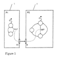
- Figure 1 describes two communicating processors that need an interblock synchronization interface.
- Figure 2 describes a programming interface for a data processing unit of an ASIC.
- Figure 3 shows a ones-counter circuit
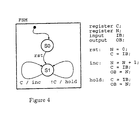
- Figure 4 depicts the same ones counter in a behavioral RT description.
- Figure 5 describes the two communicating processors of fig. 1, expanded according to the present invention with the synchronizer object.
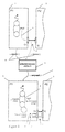
- Figure 6 depicts the programming interface of figure 2 as a behavioral reuse object according to the present invention.
- Figure 7 shows the ones-counter behavioral RT as in figure 4, expanded according to the present invention with the prog_itf object.
- Figure 8 describes schematically the present invention.
- the invention concerns a method for behavioral reuse.
- the advantage over current, structural reuse, is that the reuse interface is defined at a much higher level.
- the reuse interface is defined at the behavioral RT level.
- the RT descriptions are entered in an object oriented environment. The following are essential advantages of this reuse method:
- FIG. 1 shows a simple case of communicating processors.
- Each of the processor's behavior is described through a finite state machine (FSM).
- the nodes indicate an execution state, while the transitions between states correspond to one clock cycle of data processing.
- Each of the FSM thus represents the schedule of an algorithm.
- the GET and PUT operations show at which clock cycles the processors communicate data. This shows that there is an input/output dependency between processors P1 (1) and P2 (2).
- processor P1 (1) produces output data every second clock cycle. This data is consumed by processor P2 (2) with a variable schedule of two or three clock cycles.
- the communication of data thus introduces a synchronization requirement between P1 and P2 to guarantee correct operation of the system.
- the current practice to solve this kind of communication consistency problem is to use one of the following methods.
- Structural reuse becomes hard, or in the best case causes an overhead in silicon and/or timing.
- the second example, a programming interface is a common feature in ASICs.
- An example is shown in figure 2. It consists of two blocks out of a synchronous ASIC design. Only the parts relevant to the programming interface are shown.
- the first is a Master Interface (11).
- the purpose of this block is to make the data processing registers of the ASIC programmable from the outside world.
- the second block, Data Processing (13) is a functional component of the ASIC.
- This block has a local controller FSM 15, that sequences instructions to a datapath. Doing this, a digital signal processing (DSP) algorithm such as equalization can be implemented. Furthermore, this local controller also performs additional instructions, which are invoked by the master interface through pgm and copy.
- DSP digital signal processing
- the data processing block 13 has two modes of operation: an active mode, and a programming mode.
- the desired mode is set by the master interface through the value of pgm.
- the data processing block also signal which mode is currently active through a status bit.
- the data register D (17) is updated when the master interface sets the copy bit and at the same time the data processing block is in programming mode.
- a simple protocol controls the programming of the data register D.
- the master interface sends a program mode request to the data processing block by setting the pgm bit.
- the data processing block will enter the program mode some cycles later and signals this to the master interface through the status bit.
- the master interface then can update the data register D by setting the copy bit.
- the design complexity of the data processing block lies in the simultaneous presence of DSP algorithm and programming protocol. As a consequence, the designer of the data processing block needs to master both a DSP algorithm schedule and a protocol. Whether the FSM is described hierarchically or not does not matter: the designer needs to think of two things at once.
- the object oriented RT data model the ones-counter.
- Figure 4 shows a behavioral RT specification of the same ones-counter.
- the specification consists of a Mealy-type state transition diagram, and three RT instructions rst, inc and hold. These correspond to the datapath actions in case of reset, observation of '0' and observation of '1' respectively.
- the behavioral specification contains all the elements that make up the object oriented model.
- the C++ specification of the same behavior shown below corresponds closely to the representation of figure 4.
- the data processing is expressed in terms of sig classes, that represent plain signals or registers (lines 3-6).
- Datapath instructions such as rst, inc, and hold are described using the sfg classes. Each of these group a number of signal expressions (lines 10-23).
- the I/O ports of the behavior are indicated using bus classes.
- the control description of the ones-counter is captured by a direct modeling of the FSM description in figure 4. Each state of the ones-counter FSM maps into one state class (lines 26-27).
- the fsm class groups a number of state classes, identifying one as the initial state (lines 28-29).
- the datapath instructions are assigned to control steps by creating FSM transitions (lines 30-32).
- a transition contains a source state, a transition condition, a datapath instruction to execute, and a target state.
- the complete RT behavior of the ones-counter thus is captured as an object hierarchy.
- the objects are typical behavioral-RT elements such as signals, instructions, and control states.
- C++ operator overloading is used extensively to construct the object hierarchy. After this C++ description has executed, a reference to the fsm object is sufficient to retrieve the entire processor description as a set of interrelated objects. The reference can be used to simulate the description and generate synthesizable HDL code for it. Both operations are similar to each other and are a specific way of interpreting the object hierarchy stored in memory.
- the design environmetn OCAPI as disclosed in EP-A-867820, is incorporated herein by reference.
- the design environment OCAPI is well suited for applying the method according to the present invention.
- OCAPI internally can use meta-code generation. With this, it is meant that there are code generators that generate new "fsm”, “sfg” and “sig” objects (instances of fsm, sig and sfg classes) which in turn can be translated to synthesizable code.
- expandable objects allows to use meta-code generation: creating expandable objects implies an indirect creation of the new objects.
- Meta-code generation is a powerful method to increase the abstraction level by which a specification can be made. This way, it is also possible to make parametrized descriptions, possibly using conditions. Therefore, it is the key method of soft-chip components, which are software programs that translate themselves to a wide range of implementations, depending on the user requirements.
- the meta-code generation mechanism is also available to one as a user. To demonstrate this, a class will be presented that generates an ASIP datapath decoder.
- An ASIP datapath when described as a timed description within OCAPI, will consist of a number of signal flowgraphs and a finite state machine (fsm).
- the signal flowgraphs express the different functions to be executed by the datapath.
- the fsm description is a degenerated one, that will use one transition per decoded instruction.
- the transition condition is expressed by the "instruction" input, and selects the appropriate signal flowgraph for execution.
- the finite state machine has a fixed, but parametrizable structure, it is subject for meta-code generation.
- the "decoder” object (which is present in OCAPI) itself is presented.
- Each instruction for the ASIP decoder is defined as a number, in addition to one to three signal flowgraphs that need to be executed when this instruction is decoded.
- the "decoder" object keeps track of the instruction numbers already used and warns one if one introduces a duplicate. If the instruction number is unique, it is split up into a number of instruction bits, and a fsm transition condition is constructed from these bits.
- an add/subtract ASIP datapath is defined. One selects addition with instruction number 0, and subtraction with instruction number 1.
- the following code (that also uses the supermacros) shows the specification.
- the inheritance to "decoder” also establishes the connection to the instruction queue.
- Figure 8 shows a summary of the present invention : a hardware design 53 is made using class library 51, resulting in objects 55 that describe an implementable description of the design.
- the objects 55 are grouped in new classes 57, which can be integrated is the class library to form an extended class library 59.
- the new classes can then be used for the design of new hardware.
- the second design 61 can be made using objects' 63, resulting in an implementable description' and second hardware'.
- Behavioral reuse is applied by a two-step process.
- the reuse problem is formulated as a (possibly parametric) expansion of RT-behavior. This is done in terms of manipulations on the OO-RT model (adding/ modifying of states, transitions, signals, or instructions).
- the manipulation is captured in an class that can be reused.
- Such a class contains an expand() method (a parametric expansion of the object), which manipulates existing OO-RT behavior.
- the arguments of expand() are called the hooks of the behavioral reuse object.
- the hooks indicate the starting point for the manipulations on the OO-RT model.
- a small example makes the concept of expand() method and hook clear. Consider adding a new state to an fsm. This can be described in a behavioral reuse class as:
- the reuse class addstate has one hook: a reference to the fsm which receives the new state.
- the expand() method of addstate appends this state to the fsm.
- Example 1 Interblock synchronization as an application of behavioral RT reuse according to the invention.
- FIG. 5 shows a part from example 1 as an input for reuse.
- This processor is connected to the processor P2 (2) via a communication bus object (3).
- the immediate implementation of such a bus object is simple wiring.
- a synchronizer object (5) comes into play.
- the synchronizer object 5 will take care of merging a synchronization protocol into Pl's OO-RT description. In P2's OO-RT description, a similar synchronizer object is used to provide a matching protocol.
- the synchronizer needs hooks (6) and an expand method (7).
- the hooks for this reuse class are a communication bus on one hand, and an FSM that reads/writes this communication bus on the other.
- the expand() method of the synchronizer modifies the OO-RT description of P1 as shown on the bottom of the figure.
- Several modifications take place during the expansion. First, a wait transition is inserted.
- new instructions are added, which provide the signaling of a synchronous handshake protocol (S. Vercauteren and Bill Lin. Hardware/software Communication and System Integration for Embedded Architectures. Design Automation of Embedded Systems, Kluwer Academic Publishers, 2:1-24, 1997).
- the signaling is done through newly created bus objects p_req (8) and p_ack (9).
- the inserted instructions include: reql and req0, which assert/deassert the request for data communication, and read, which samples the acknowledge bus.
- the sampled value is used as a transition condition in the expanded FSM.
- the protocol implementation of GET (as for instance in processor P2) proceeds by a similar, symmetrical expansion.
- the parametric expansion algorithm, done by the reuse class synchronizer can be as follows : 0: ***definitions : 1: - for any transition in a finite state machine 2: running from state 'A' to state 'B', 3: call 'A' a source state of this transition 4: call 'B' a target state of this transition 5: - for any transition in a finite state machine 6: with source state 'A' and target state 'B', 7: call 'pred(transition)' any transition for 8: which 'A' is a target state 9: *** algorithm 10: for each synchronized I/O access transition ⁇ 11: add new wait transition on the source state 12: update transition conditions from the source state 13: ⁇ 14: for each synchronized I/O access transition ⁇ 15: insert instruction reql on all pred(transition) 16: insert instruction req0 on all !pred(transition) 17: ⁇ 18: for each transition 19: insert instruction read
- the algorithm shown has still certain limitations. For example, two I/O accesses subject to synchronization in the same transition are not allowed. However, by formulating the synchronization problem as a behavioral reuse problem, the synchronizer object can be readily replaced by a new, more sophisticated one without additional modifications to the original behavior of P1.
- Example 2 The programming interface as a behavioral reuse object according to the present invention.
- FIG. 6 shows the decomposition of the data processing block (31).
- the designer is responsible for the description of the data processing (33) itself, but does not need to worry about the protocol with the master interface. Rather, this protocol is available through an class prog_itf (35).
- a number of hooks must be given to the programming interface. These include: a reference to the data register for implementing a write operation from the master interface and a reference to a state at which the block can go into programming mode. Given these hooks, the expand method of prog_itf can be called to implement the programming interface into the block. An example of the operation of prog_itf is shown in figure 7.
- a similar class can be used for the construction of an I2C programming interface.
- the interface class was applied to 6 different data processors in the modem.
- the complete description of the modem in C++ at the OO-RT level took 4426 lines of code, while the RT-VHDL, generated out of this code, took 21798 lines.
- the gain in code size was for a large part credited to the behavioral reuse mechanism of the programming interface.
- Example 3 comparison of two 80-kilogate designs designed with and without reuse according to the present invention.
- the method according to the present invention was applied on two 80-kilogate designs: an upstream Cable Modem and a DECT base station transceiver.
- the first line indicates the C++ line count in the OO-RT model.
- the RT-VHDL line count of generated code is shown on the second line.
- the type of code is divided into reuse (reusable classes such as programming interfaces obtained according to the present invention), body (line count of individual block bodies), headers (.h files for C++ and entity declarations for VHDL) and system (the system level netlist and testbench drivers).
Landscapes
- Engineering & Computer Science (AREA)
- Computer Hardware Design (AREA)
- Physics & Mathematics (AREA)
- Theoretical Computer Science (AREA)
- Evolutionary Computation (AREA)
- Geometry (AREA)
- General Engineering & Computer Science (AREA)
- General Physics & Mathematics (AREA)
- Stored Programmes (AREA)
- Design And Manufacture Of Integrated Circuits (AREA)
Priority Applications (1)
| Application Number | Priority Date | Filing Date | Title |
|---|---|---|---|
| EP99870149A EP0991000A3 (fr) | 1998-09-29 | 1999-07-09 | Réutilisation de composants matériels |
Applications Claiming Priority (5)
| Application Number | Priority Date | Filing Date | Title |
|---|---|---|---|
| US273089 | 1994-07-11 | ||
| EP98870205 | 1998-09-29 | ||
| EP98870205 | 1998-09-29 | ||
| US09/273,089 US7113901B1 (en) | 1997-03-14 | 1999-03-19 | Reuse of hardware components |
| EP99870149A EP0991000A3 (fr) | 1998-09-29 | 1999-07-09 | Réutilisation de composants matériels |
Publications (2)
| Publication Number | Publication Date |
|---|---|
| EP0991000A2 true EP0991000A2 (fr) | 2000-04-05 |
| EP0991000A3 EP0991000A3 (fr) | 2006-05-17 |
Family
ID=27239780
Family Applications (1)
| Application Number | Title | Priority Date | Filing Date |
|---|---|---|---|
| EP99870149A Withdrawn EP0991000A3 (fr) | 1998-09-29 | 1999-07-09 | Réutilisation de composants matériels |
Country Status (1)
| Country | Link |
|---|---|
| EP (1) | EP0991000A3 (fr) |
Cited By (2)
| Publication number | Priority date | Publication date | Assignee | Title |
|---|---|---|---|---|
| EP1296206A3 (fr) * | 2001-08-17 | 2003-07-30 | Air Products And Chemicals, Inc. | Lignes de production multiples pour une installation de traitement utilisant un ensemble de composants standards commun |
| US10089426B2 (en) | 2013-12-12 | 2018-10-02 | Tokyo Institute Of Technology | Logic circuit generation device and method |
Family Cites Families (2)
| Publication number | Priority date | Publication date | Assignee | Title |
|---|---|---|---|---|
| US5673199A (en) * | 1995-05-01 | 1997-09-30 | Hughes Electronics | Computer aided reuse tool |
| EP0772140B1 (fr) * | 1995-10-23 | 2004-01-07 | Interuniversitair Micro-Elektronica Centrum Vzw | Environnement et procédé de conception pour la conception combinée de matériel et de logiciel |
-
1999
- 1999-07-09 EP EP99870149A patent/EP0991000A3/fr not_active Withdrawn
Cited By (3)
| Publication number | Priority date | Publication date | Assignee | Title |
|---|---|---|---|---|
| EP1296206A3 (fr) * | 2001-08-17 | 2003-07-30 | Air Products And Chemicals, Inc. | Lignes de production multiples pour une installation de traitement utilisant un ensemble de composants standards commun |
| US7003359B2 (en) | 2001-08-17 | 2006-02-21 | Air Products And Chemicals, Inc. | Multiple process plant product lines from a common set of engineered components |
| US10089426B2 (en) | 2013-12-12 | 2018-10-02 | Tokyo Institute Of Technology | Logic circuit generation device and method |
Also Published As
| Publication number | Publication date |
|---|---|
| EP0991000A3 (fr) | 2006-05-17 |
Similar Documents
| Publication | Publication Date | Title |
|---|---|---|
| JP3835754B2 (ja) | 集積回路の設計方法及びそれによって設計された集積回路 | |
| US5764951A (en) | Methods for automatically pipelining loops | |
| Swan | An introduction to system level modeling in SystemC 2.0 | |
| Edwards et al. | Balsa: An asynchronous hardware synthesis language | |
| US6233540B1 (en) | Design environment and a method for generating an implementable description of a digital system | |
| US7006960B2 (en) | Design apparatus and a method for generating an implementable description of a digital system | |
| US6226776B1 (en) | System for converting hardware designs in high-level programming language to hardware implementations | |
| Liao | Towards a new standard for system-level design | |
| EP2472407A2 (fr) | Procédé et appareil permettant de modéliser des systèmes de flux de données et réalisation du matériel | |
| US6883147B1 (en) | Method and system for generating a circuit design including a peripheral component connected to a bus | |
| US6865526B1 (en) | Method for core-based system-level power modeling using object-oriented techniques | |
| EP0772140A1 (fr) | Environnement et procédé de conception pour la conception combinée de matériel et de logiciel | |
| Josephs et al. | Modeling and design of asynchronous circuits | |
| Schaumont et al. | Hardware reuse at the behavioral level | |
| Semba et al. | RTL conversion method from pipelined synchronous RTL models into asynchronous ones | |
| O'Donnell | Overview of Hydra: A concurrent language for synchronous digital circuit design | |
| US7113901B1 (en) | Reuse of hardware components | |
| Kuhn et al. | Description and simulation of hardware/software systems with Java | |
| US9454630B1 (en) | Graphical representation of integrated circuits | |
| EP0991000A2 (fr) | Réutilisation de composants matériels | |
| US7496869B1 (en) | Method and apparatus for implementing a program language description of a circuit design for an integrated circuit | |
| Gladigau et al. | A system-level synthesis approach from formal application models to generic bus-based MPSoCs | |
| Amon et al. | Operation/Event Graphs: A design representation for timing behavior | |
| JP2000113026A (ja) | ハ―ドウエア構成要素の再利用 | |
| Sridhar | Asynchronous design techniques |
Legal Events
| Date | Code | Title | Description |
|---|---|---|---|
| PUAI | Public reference made under article 153(3) epc to a published international application that has entered the european phase |
Free format text: ORIGINAL CODE: 0009012 |
|
| AK | Designated contracting states |
Kind code of ref document: A2 Designated state(s): AT BE CH CY DE DK ES FI FR GB GR IE IT LI LU MC NL PT SE |
|
| AX | Request for extension of the european patent |
Free format text: AL;LT;LV;MK;RO;SI |
|
| PUAL | Search report despatched |
Free format text: ORIGINAL CODE: 0009013 |
|
| AK | Designated contracting states |
Kind code of ref document: A3 Designated state(s): AT BE CH CY DE DK ES FI FR GB GR IE IT LI LU MC NL PT SE |
|
| AX | Request for extension of the european patent |
Extension state: AL LT LV MK RO SI |
|
| STAA | Information on the status of an ep patent application or granted ep patent |
Free format text: STATUS: THE APPLICATION IS DEEMED TO BE WITHDRAWN |
|
| 18D | Application deemed to be withdrawn |
Effective date: 20060201 |