EP0991021A2 - Bildrekonstruierung von Kegelstrahldaten - Google Patents
Bildrekonstruierung von Kegelstrahldaten Download PDFInfo
- Publication number
- EP0991021A2 EP0991021A2 EP99307610A EP99307610A EP0991021A2 EP 0991021 A2 EP0991021 A2 EP 0991021A2 EP 99307610 A EP99307610 A EP 99307610A EP 99307610 A EP99307610 A EP 99307610A EP 0991021 A2 EP0991021 A2 EP 0991021A2
- Authority
- EP
- European Patent Office
- Prior art keywords
- data
- vertex
- reconstruction
- radiation
- source
- Prior art date
- Legal status (The legal status is an assumption and is not a legal conclusion. Google has not performed a legal analysis and makes no representation as to the accuracy of the status listed.)
- Withdrawn
Links
Images


Classifications
-
- G—PHYSICS
- G06—COMPUTING OR CALCULATING; COUNTING
- G06T—IMAGE DATA PROCESSING OR GENERATION, IN GENERAL
- G06T12/00—Tomographic reconstruction from projections
- G06T12/10—Image preprocessing, e.g. calibration, positioning of sources or scatter correction
-
- A—HUMAN NECESSITIES
- A61—MEDICAL OR VETERINARY SCIENCE; HYGIENE
- A61B—DIAGNOSIS; SURGERY; IDENTIFICATION
- A61B6/00—Apparatus or devices for radiation diagnosis; Apparatus or devices for radiation diagnosis combined with radiation therapy equipment
- A61B6/02—Arrangements for diagnosis sequentially in different planes; Stereoscopic radiation diagnosis
- A61B6/027—Arrangements for diagnosis sequentially in different planes; Stereoscopic radiation diagnosis characterised by the use of a particular data acquisition trajectory, e.g. helical or spiral
-
- G—PHYSICS
- G06—COMPUTING OR CALCULATING; COUNTING
- G06T—IMAGE DATA PROCESSING OR GENERATION, IN GENERAL
- G06T2211/00—Image generation
- G06T2211/40—Computed tomography
- G06T2211/432—Truncation
-
- Y—GENERAL TAGGING OF NEW TECHNOLOGICAL DEVELOPMENTS; GENERAL TAGGING OF CROSS-SECTIONAL TECHNOLOGIES SPANNING OVER SEVERAL SECTIONS OF THE IPC; TECHNICAL SUBJECTS COVERED BY FORMER USPC CROSS-REFERENCE ART COLLECTIONS [XRACs] AND DIGESTS
- Y10—TECHNICAL SUBJECTS COVERED BY FORMER USPC
- Y10S—TECHNICAL SUBJECTS COVERED BY FORMER USPC CROSS-REFERENCE ART COLLECTIONS [XRACs] AND DIGESTS
- Y10S378/00—X-ray or gamma ray systems or devices
- Y10S378/901—Computer tomography program or processor
Definitions
- the present invention relates to image reconstruction. It finds particular application in conjunction with CT scanners, and will be described with particular reference thereto. However, it is to be appreciated that the present invention is also amenable to other like applications.
- spiral CT scanners include an x-ray source which projects a thin slice or beam of radiation.
- the x-ray source is mounted for rotational movement about a subject who is moving along the axis of rotation.
- An arc or ring of radiation detectors receive radiation which has traversed the subject.
- Data from the radiation detectors represents a single spiraling slice through the subject.
- the data from the detectors is reconstructed into a three-dimensional image representation.
- a pair or more of radiation detectors can be disposed next to each other. This enables two or more slices of data to be collected concurrently. However, like the single slice scanner, only intra-slice data is used in the reconstruction process.
- the additional radiation supplied by the cone beam is beneficial in imaging, it has the detrimental side effect of increasing the dosage to the subject.
- the high dosage enables a volume to be reconstructed with fewer rotations of the cone beam.
- a method of image reconstruction from partial cone beam data includes collecting the partial cone beam data in two-dimensional arrays.
- the collected data corresponds to rays of radiation diverging in two dimensions from a common vertex as the vertex travels along a curve.
- Each element of the data is related to line integrals of an object being reconstructed taken along each ray.
- a local coordinate system is defined and the data is pre-weighted.
- a one-dimensional convolution of the pre-weighted data is computed in the local coordinate system along a direction which is tangential to the curve along which the vertex travels. The convolved data is then weighted and three-dimensionally backprojected.
- a CT scanner includes a first gantry which defines an examination region.
- a rotating gantry is mounted on the first gantry for rotation about the examination region.
- a source of penetrating radiation is arranged on the rotating gantry for rotation therewith.
- the source of penetrating radiation emits a cone-shaped beam of radiation that passes through the examination region as the rotating gantry rotates.
- a subject support holds a subject being examined at least partially within the examination region and at least one of the first gantry and the subject support is translated such that the subject passes through the examination region while the rotating gantry is rotated. In this manner, the source of penetrating radiation follows a helical path relative to the subject.
- a two-dimensional array of radiation detectors is arranged to receive the radiation emitted from the source of penetrating radiation after it has traversed the examination region.
- a reconstruction processor reconstructs images of the subject from data collected by the two-dimensional array of radiation detectors.
- the reconstruction processor includes a first data processor which pre-weights the data.
- a convolver takes the data from the first data processor and performs a one-dimensional convolution on it in a local coordinate system along a direction which is tangential to the helical path.
- a second data processor takes the data from the convolver and weights it.
- a backprojector then takes the data from the second data processor and three-dimensionally backprojects it into an image memory.
- a human viewable display accesses the image memory to display reconstructed images of the subject.
- the invention permits increased efficiency in the reconstruction process.
- the invention also permits simplification of the reconstruction process for partial cone beam data. Also, it is possible to achieve high-quality images reconstructed from partial data sets, i.e., it is possible to truncate the data in at least one direction without a loss of image quality.
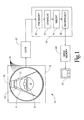
- a CT scanner 10 includes a stationary gantry 12 which defines an examination region 14 .
- a rotating gantry 16 is mounted on the stationary gantry 12 for rotation about the examination region 14 .
- a source of penetrating radiation 20 such as an x-ray tube, is arranged on the rotating gantry 16 for rotation therewith.
- the source of penetrating radiation produces a cone-shaped beam of radiation 22 that passes through the examination region 14 as the rotating gantry 16 rotates.
- a collimator and shutter assembly 24 forms the beam of radiation 22 and selectively gates the beam 22 on and off. Alternately, the radiation beam 22 is gated on and off electronically at the source 20 .
- a subject support 30 such as a couch or the like, suspends or otherwise holds a subject being examined or imaged at least partially within the examination region 14 . Moreover, as the rotating gantry 16 rotates, the support 30 , and consequently the subject thereon, are translated along a central horizontal axis of the examination region 14 . In this manner, the source 20 follows a helical path relative to the subject.
- the support 30 remains stationary while the "stationary gantry" 12 is translated or otherwise moved relative to the subject such that the source 20 follows a helical path relative thereto.
- a plurality of rings of radiation detectors 40 are mounted peripherally around the examination region 14 on the stationary gantry 12 .
- a third generation CT scanner is employed with the radiation detectors 40 mounted on the rotating gantry 16 on a side of the examination region 14 opposite the source 20 such that they span the area defined by the cone-shaped beam of radiation 22 .
- the radiation detectors 40 are arranged such that a two-dimensional array thereof receive the radiation emitted from the source 20 after it has traversed the examination region 14 .
- a source cone geometry an array of detectors which span the radiation 22 emanating from the source 20 are sampled concurrently at short time intervals as the source 20 rotates behind the examination region 14 to generate a source view.
- the detectors are sampled a multiplicity of times as the source 20 rotates behind the examination region 14 to generate a detector view.
- the path between the source 20 and each of the radiation detectors 40 is denoted as a ray.
- the radiation detectors 40 convert the detected radiation into electronic data. That is to say, each of the radiation detectors produces an output signal which is proportional to the intensity of received radiation.
- a reference detector may detect radiation which has not traversed the examination region 14 . A difference between the magnitude of radiation received by the reference detector and each active radiation detector 40 provides an indication of the amount of radiation attenuation along a corresponding ray of sampled radiation.
- each view or two-dimensional array of data represents a cone of rays having its vertex at one of the radiation detectors 40 collected over a short period of time as the source 20 rotates behind the examination region 14 from the detectors.
- each view or two-dimensional array of data represents a cone of rays having a vertex at the source 20 collected by a concurrent sampling of detectors.
- a gantry acquisition memory board 42 receives sampled data from the radiation detectors 40 .
- the gantry acquisition memory board 42 optionally shuffles the data to transform it from a detector cone geometry to a source cone geometry or vice versa and performs a ripple filtering operation before passing the data to an image processor 50 .
- the image processor 50 processes the view data from the gantry acquisition board 42 and three-dimensionally backprojects it into an image memory 60 .
- the image processor 50 performs mathematical manipulations which convolve each view with an appropriate filter or convolution function for the view format. More specifically, a first data processor 52 pre-weights the data. A convolver 54 then performs a one-dimensional convolution. After a second data processor 56 weights the convolved data, a backprojector 58 three-dimensionally backprojects the data into the image memory 60 . A human viewable display 62 , such as a monitor, accesses the image memory to selectively display reconstructed images of the scanned subject.
- an "exact inversion formula” is established. Unlike the classical inversion formula for reconstruction of a two-dimensional (2D) subject from a set of fan beam data, the inversion formula herein assumes that: (i) the subject is represented by a true three-dimensional (3D) real function, (ii) the data is cone beam data, and (iii) the subject is scanned in a helical fashion.
- the "exact” reconstruction takes the form of a convolution back-projection, wherein both the convolution and the back-projection are 3D in nature.
- the 3D convolution is reduced or approximated by weighing a set of one-dimensional (1D) convolutions.
- the kernel for this 1D convolution is the classical 2D reconstruction kernel, i.e. a ramp convolver.
- the 1D convolution is performed in the direction of the tangent to the helix at the position of the vertex of the cone beam data, i.e., the location of the source 20 .
- the weight for the convolved data along each ray depends on the ray's position in the cone as well as the position of the vertex of the cone relative to the reconstruction point.
- the subject to be reconstructed is represented by a function f from R 3 to R , and is of finite extent, i.e., of compact support;
- ⁇ x ⁇ 1 ⁇ ;
- the inner product of two points x and y in R 3 is denoted by ⁇ x, y>; and, the Fourier transform of a function h is denoted by h and .
- the data is in the form of line integrals of the scanned subject f.
- a positive half-line originating from a point V and extending in a direction ⁇ , ⁇ ⁇ S, is the set ⁇ V + r ⁇
- ⁇ ⁇ S ⁇ represents the set of line integrals off in a cone of vertex V. Due to the finite extent of the function f, there exits a cone defined by a subset C of S such that g v ( ⁇ )
- 0 if ⁇ is outside of C, assuming that the vertex V is outside of the support of the function f.
- the classical inversion formula to reconstruct a 2D subject from its line integrals is based on the projection theorem which states that the 2D Fourier transform of the function to be reconstructed along a direction ⁇ is equal to the 1D Fourier transform of the integrals of the function along lines perpendicular to the direction ⁇ .
- a 3D version of this theorem uses planar integrals. More precisely, the 3D Fourier transform of the function to be reconstructed along a direction ⁇ is equal to the 1D Fourier transform of the integrals of the function along planes perpendicular to the direction ⁇ .
- the function is then reconstructed by taking the inverse Fourier transform when its Fourier transform along all directions ⁇ ⁇ S are estimated. While no such projection theorem exists for fan beam or cone beam geometries, the Fourier transform of the function f is related to the cone beam data by the following lemma.
- the 3D Fourier transform of f along a given direction ⁇ ⁇ S is estimated from the cone beam data provided that the vertex V of the cone describes a curve with the property that the plane going through the vertex V and perpendicular to the direction ⁇ sweeps through the entire subject.
- ⁇ f ( ⁇ ) ⁇ ⁇ ( g ⁇ ( ⁇ ) ( ⁇ )- g ⁇ ( ⁇ ) (- ⁇ ))
- the estimation of f from cone beam data is done by estimating its Fourier transform along all directions ⁇ using the above equation (12).
- the curve described by the vertices of the cones is to be bounded, then the curve should be non-planar.
- the solution is not unique, and the number of solutions depends on the value u, and the direction ⁇ . For these reasons, the equation which relates the Fourier transform off with cone beam data takes the multiplicity condition into account.
- ⁇ f ( ⁇ ) ⁇ ⁇ ( g ⁇ ( ⁇ ) ( ⁇ )- g ⁇ ( ⁇ ) (- ⁇ ))
- This multiplicity condition is expressed also by the following integral equation: ⁇ ⁇
- M ( ⁇ , s ) ⁇ ( ⁇ ( ⁇ )- ⁇ ( s ), ⁇ >) ds 1
- the inversion formula to compute f from the cone beam data is obtained by writing the inverse Fourier transform using the spherical coordinate system:
- Q is the 3D inverse Fourier transform of the product of 3 functions
- q ⁇ and I ⁇ are the 3D Fourier transform of the functions defined by
- , and M respectively, and where g - ⁇ ( ⁇ ) is defined by the equation: g - ⁇ ( ⁇ ) ( ⁇ ) g ⁇ ( ⁇ ) (- ⁇ )
- g ⁇ ( ⁇ ) * q ⁇ ( x - ⁇ ( ⁇ )) ⁇ R 3 g ⁇ ( ⁇ ) ( x - ⁇ ( ⁇ )- ⁇ ) q ⁇ ( ⁇ ) d ⁇
- I ⁇ is the 3D Fourier transform of the multiplicity function M ⁇ .
- M ⁇ is the 3D Fourier transform of the multiplicity function M ⁇ .
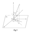
- the last integral from equating (46) is the 2D Fourier transform of the restriction of M ⁇ on the plane P(a) evaluated at the orthogonal projection ofx - ⁇ ( ⁇ ) onto P(a). Therefore, where b is the norm of the orthogonal projection of x- ⁇ ( ⁇ ) onto the plane P(a), and ⁇ is the angle between the projections of x- ⁇ ( ⁇ ) and ⁇ onto P(a), as shown in FIGURE 5.
- This Fourier transform is a sum ofa series with the first term equal to the Dirac distribution ⁇ at x - ⁇ ( ⁇ ) weighted with a constant w(a).
- J n ( b , ⁇ ) i ⁇ 2 b 2 ⁇ z n +1 dz ( z - z 1 ) 2 ( z - z 2 ) 2
- z 1 i ( ⁇ b + 1 + ⁇ 2 b 2 )
- z 2 i ( ⁇ b - 1 + ⁇ 2 b 2 )
- J 0 ( b , ⁇ ) ⁇ 2 ⁇ b 2 + ⁇ 2 3
- the inversion formula assumes that, for each ⁇ , data corresponds to line integrals in a cone with vertex at ⁇ ( ⁇ ), and that the set of vertices ⁇ ⁇ ( ⁇ )
- the convolution Q(x, ⁇ ) consists of three terms. The first term depends on line integrals of f or "collected data", the second term depends solely on the slope ⁇ '( ⁇ ), and the last term depends on the number of intersection points of the curve ⁇ ( ⁇ )
- the convolution Q(x, ⁇ ) is conveniently computed in a local coordinate system with one of the axis being parallel to the tangent vector ⁇ '( ⁇ ). Being that the third term of the convolution is constant, or at least approximated by a (ray-dependent) multiplicative function, the 3D convolution Q(x, ⁇ ) is obtained by performing a 1D convolution of "pre-weighted data" H ⁇ along rays within the plane parallel to the tangent vector ⁇ '( ⁇ ) and going through both the vertex ⁇ ( ⁇ ) and the reconstruction point x.
- the convolver is the classical ramp convolver which is used in 2D reconstruction.
- the convolution of the Fourier transform of the multiplicity function with the data convolved with the classical ramp reconstruction filter is conveniently approximated by weighing the convolved data with a weight which depends on the vertex positions and ray positions within the vertex. For each ray position within a given vertex of the cone beam, the weight is precomputed and is proportional to the sum of all the multiplicity functions corresponding to all planes containing the ray.
- the multiplicity function is a function of directions. For a given direction, the function depends on the number of intersections of the portion of the helix used in the backprojection with the plane going through the vertex and perpendicular to the direction.
- the multiplicity function is also defined to take into account on how much weight is given to the cone beam data.
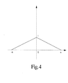
- the weight is 1 if the position of the vertex is at the same level as the reconstruction point, and the weight goes to zero as the level of the position of the vertex of the cone goes a half-revolution away from the level of the reconstruction point.
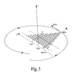
- ⁇ ( ⁇ ) ( Rcos ⁇ , Rsin ⁇ , ⁇ ) with constants ⁇ and ⁇ derived from the speeds of rotation of the source 20 and translation of the support 30 .
- the ratio w R/(T - R) is computed in order to find the ray going through the reconstruction point x, and to provide the weight for the backprojection.
- the vertex of the cone is determined by the above computed value V.
- the convolution backprojected from a particular view is the 1D convolution of the pre-weighted data along a fan going through the reconstruction point, the vertex of the cone, and parallel to the tangent vector of the helix.
- the convolved data is taken along 3 fans, each received by a corresponding front, centre, and back ring of radiation detectors 40 .
- the convolved data to be backprojected at this view is obtained by performing a 2D interpolation of the convolved data of the 3 fans based on the index of the ray deduced from wU, and the index ofthe cone vertex deduced from V (see FIGURE 6).
- the quadrature of the inversion formula is approximated by a finite sum of these backprojected values, from a preselected first view to a preselected last view.
- the convolved data along the 3 fans are done based on the results previously established herein. More precisely, line integrals which are proportional to the fan data are pre-weighted first to generate 3 fans of H ⁇ .
- Each detector fan is assumed to be collected in the direction of the tangent vector.
- These pre-weighted 3 fans are then convolved with the image reconstruction kernel. The fans are again weighted and then backprojected into the image memory 60 . In this manner, the image reconstruction is carried out.
Landscapes
- Life Sciences & Earth Sciences (AREA)
- Engineering & Computer Science (AREA)
- Health & Medical Sciences (AREA)
- Physics & Mathematics (AREA)
- Medical Informatics (AREA)
- Radiology & Medical Imaging (AREA)
- Heart & Thoracic Surgery (AREA)
- High Energy & Nuclear Physics (AREA)
- Theoretical Computer Science (AREA)
- Nuclear Medicine, Radiotherapy & Molecular Imaging (AREA)
- Optics & Photonics (AREA)
- Pathology (AREA)
- General Physics & Mathematics (AREA)
- Biomedical Technology (AREA)
- Biophysics (AREA)
- Molecular Biology (AREA)
- Surgery (AREA)
- Animal Behavior & Ethology (AREA)
- General Health & Medical Sciences (AREA)
- Public Health (AREA)
- Veterinary Medicine (AREA)
- Apparatus For Radiation Diagnosis (AREA)
- Image Processing (AREA)
- Image Analysis (AREA)
Applications Claiming Priority (2)
| Application Number | Priority Date | Filing Date | Title |
|---|---|---|---|
| US164013 | 1998-09-30 | ||
| US09/164,013 US6097784A (en) | 1998-09-30 | 1998-09-30 | 3D image reconstruction for helical partial cone beam data |
Publications (2)
| Publication Number | Publication Date |
|---|---|
| EP0991021A2 true EP0991021A2 (de) | 2000-04-05 |
| EP0991021A3 EP0991021A3 (de) | 2004-03-31 |
Family
ID=22592603
Family Applications (1)
| Application Number | Title | Priority Date | Filing Date |
|---|---|---|---|
| EP99307610A Withdrawn EP0991021A3 (de) | 1998-09-30 | 1999-09-27 | Bildrekonstruierung von Kegelstrahldaten |
Country Status (3)
| Country | Link |
|---|---|
| US (1) | US6097784A (de) |
| EP (1) | EP0991021A3 (de) |
| JP (1) | JP2000126173A (de) |
Cited By (3)
| Publication number | Priority date | Publication date | Assignee | Title |
|---|---|---|---|---|
| EP0997849A3 (de) * | 1998-10-29 | 2004-03-31 | Koninklijke Philips Electronics N.V. | Bildrekonstruktion |
| EP1429658A4 (de) * | 2001-08-16 | 2009-04-22 | Research Foundation Univ Central Florida Inc | Exakt gefilterter rückprojektionsalgorithmus (fbp) für die spiralcomputertomographie |
| EP2466725A1 (de) | 2010-12-15 | 2012-06-20 | Infranor Holding S.A. | Synchronmotor mit Permanentmagneten |
Families Citing this family (15)
| Publication number | Priority date | Publication date | Assignee | Title |
|---|---|---|---|---|
| US6461040B1 (en) | 1998-11-12 | 2002-10-08 | Koninklijke Philips Electronics N.V. | Apparatus and method to correct for position errors in diagnostic imaging |
| DE10244181A1 (de) * | 2002-09-23 | 2004-04-01 | Siemens Ag | Verfahren zur Bilderstellung in der Computertomographie und CT-Gerät zur Durchführung des Verfahrens |
| JP4360817B2 (ja) * | 2002-10-18 | 2009-11-11 | 株式会社日立メディコ | 放射線断層撮影装置 |
| JP2007527253A (ja) * | 2003-02-14 | 2007-09-27 | コーニンクレッカ フィリップス エレクトロニクス エヌ ヴィ | 冗長データを含むヘリカルコーンビーム・コンピュータ断層撮像法に対する正確な画像再構成システム及び方法 |
| US7209535B2 (en) * | 2003-06-20 | 2007-04-24 | Wisconsin Alumni Research Foundation | Fourier space tomographic image reconstruction method |
| US6990167B2 (en) * | 2003-08-29 | 2006-01-24 | Wisconsin Alumni Research Foundation | Image reconstruction method for divergent beam scanner |
| US7539281B2 (en) * | 2004-10-15 | 2009-05-26 | General Electric Company | Methods and apparatus for reconstruction in helical cone beam volumetric CT |
| EP1828985A1 (de) * | 2004-11-24 | 2007-09-05 | Wisconsin Alumni Research Foundation | Fächerstrahl- und conusstrahl-bildrekonstruktion unter verwendung gefilterter rückprojektion differenzierter projektionsdaten |
| US7477720B2 (en) * | 2005-06-28 | 2009-01-13 | University Of Utah Research Foundation | Cone-beam reconstruction using backprojection of locally filtered projections and X-ray CT apparatus |
| US8304242B2 (en) * | 2007-12-17 | 2012-11-06 | Life Technologies Corporation | Methods for detecting defects in inorganic-coated polymer surfaces |
| US20130020507A1 (en) | 2010-06-17 | 2013-01-24 | Life Technologies Corporation | Methods for Detecting Defects in Inorganic-Coated Polymer Surfaces |
| US8971599B2 (en) | 2010-12-20 | 2015-03-03 | General Electric Company | Tomographic iterative reconstruction |
| CN103674979B (zh) * | 2012-09-19 | 2016-12-21 | 同方威视技术股份有限公司 | 一种行李物品ct安检系统及其探测器装置 |
| US9091628B2 (en) | 2012-12-21 | 2015-07-28 | L-3 Communications Security And Detection Systems, Inc. | 3D mapping with two orthogonal imaging views |
| US9757088B2 (en) * | 2014-11-13 | 2017-09-12 | Toshiba Medical Systems Corporation | Detector apparatus for cone beam computed tomography |
Family Cites Families (8)
| Publication number | Priority date | Publication date | Assignee | Title |
|---|---|---|---|---|
| US4789929A (en) * | 1987-05-14 | 1988-12-06 | Hitachi Medical Corporation | CT system for spirally scanning subject on a movable bed synchronized to X-ray tube revolution |
| US5485493A (en) * | 1988-10-20 | 1996-01-16 | Picker International, Inc. | Multiple detector ring spiral scanner with relatively adjustable helical paths |
| JPH0728862B2 (ja) * | 1989-02-13 | 1995-04-05 | 株式会社東芝 | Ct装置 |
| US5090037A (en) * | 1990-11-19 | 1992-02-18 | General Electric Company | Helical scanning computed tomography with tracking x-ray source |
| US5404293A (en) * | 1991-06-11 | 1995-04-04 | The University Of Utah | Cone beam reconstruction using helical data collection paths |
| US5375156A (en) * | 1992-03-31 | 1994-12-20 | Siemens Medical Systems, Inc. | Method and apparatus for 3-D computer tomography |
| US5377250A (en) * | 1992-08-07 | 1994-12-27 | General Electric Company | Reconstruction method for helical scanning computed tomography apparatus with multi-row detector array |
| US5625660A (en) * | 1995-06-30 | 1997-04-29 | Picker International, Inc. | Image reconstruction from helical partial cone-beam data |
-
1998
- 1998-09-30 US US09/164,013 patent/US6097784A/en not_active Expired - Fee Related
-
1999
- 1999-09-27 EP EP99307610A patent/EP0991021A3/de not_active Withdrawn
- 1999-09-30 JP JP11315780A patent/JP2000126173A/ja not_active Abandoned
Non-Patent Citations (1)
| Title |
|---|
| XIAO-HONG YAN AND RICHARD M LEAHY: "Cone beam tomography with circular, elliptical and spiral orbits", PHYS. MED. BIOL., vol. 37, no. 3, March 1992 (1992-03-01), pages 493 - 506, XP020021955, DOI: doi:10.1088/0031-9155/37/3/001 * |
Cited By (3)
| Publication number | Priority date | Publication date | Assignee | Title |
|---|---|---|---|---|
| EP0997849A3 (de) * | 1998-10-29 | 2004-03-31 | Koninklijke Philips Electronics N.V. | Bildrekonstruktion |
| EP1429658A4 (de) * | 2001-08-16 | 2009-04-22 | Research Foundation Univ Central Florida Inc | Exakt gefilterter rückprojektionsalgorithmus (fbp) für die spiralcomputertomographie |
| EP2466725A1 (de) | 2010-12-15 | 2012-06-20 | Infranor Holding S.A. | Synchronmotor mit Permanentmagneten |
Also Published As
| Publication number | Publication date |
|---|---|
| EP0991021A3 (de) | 2004-03-31 |
| JP2000126173A (ja) | 2000-05-09 |
| US6097784A (en) | 2000-08-01 |
Similar Documents
| Publication | Publication Date | Title |
|---|---|---|
| EP0997849B1 (de) | Bildrekonstruktion | |
| EP0751484B1 (de) | Bildrekonstruierung von spiralabgetasteten Teilkegelstrahldaten | |
| Turbell | Cone-beam reconstruction using filtered backprojection | |
| US6990167B2 (en) | Image reconstruction method for divergent beam scanner | |
| Defrise et al. | A cone-beam reconstruction algorithm using shift-variant filtering and cone-beam backprojection | |
| EP0492895B1 (de) | 3-D-Bilderrekonstruktion | |
| Noo et al. | A two-step Hilbert transform method for 2D image reconstruction | |
| US6415013B1 (en) | Backprojection methods and apparatus for computed tomography imaging systems | |
| US5400255A (en) | Reconstruction of images from cone beam data | |
| US6097784A (en) | 3D image reconstruction for helical partial cone beam data | |
| US7251307B2 (en) | Fan-beam and cone-beam image reconstruction using filtered backprojection of differentiated projection data | |
| EP0928458B1 (de) | Eine computertomographische methode und ein computertomograph | |
| EP1644897B1 (de) | TOMOGRAPHISCHES FOURIER-BILDREKONSTRUKTIONSVERFAHREN FÜR Fächerstrahl-DATEN | |
| Kudo et al. | Exact and approximate algorithms for helical cone-beam CT | |
| Defrise et al. | Image reconstruction from truncated, two-dimensional, parallel projections | |
| EP1800264B1 (de) | Bildrekonstruktion mit voxelabhängiger Interpolation | |
| Noo et al. | Cone-beam reconstruction from general discrete vertex sets using Radon rebinning algorithms | |
| Tanaka et al. | A Fourier rebinning algorithm incorporating spectral transfer efficiency for 3D PET | |
| Defrise et al. | Improved two-dimensional rebinning of helical cone-beam computerized tomography data using John’s equation | |
| Grangeat et al. | Evaluation of the 3-D Radon transform algorithm for cone beam reconstruction | |
| Besson | CT fan-beam parametrizations leading to shift-invariant filtering | |
| Hsieh et al. | Image reconstruction using a generalized natural pixel basis | |
| Zhao et al. | Generalized fourier slice theorem for cone-beam image reconstruction | |
| Zeng et al. | Iterative and analytical reconstruction algorithms for varying-focal-length cone-beam projections | |
| Zeng | 3D image reconstruction |
Legal Events
| Date | Code | Title | Description |
|---|---|---|---|
| PUAI | Public reference made under article 153(3) epc to a published international application that has entered the european phase |
Free format text: ORIGINAL CODE: 0009012 |
|
| AK | Designated contracting states |
Kind code of ref document: A2 Designated state(s): AT BE CH CY DE DK ES FI FR GB GR IE IT LI LU MC NL PT SE |
|
| AX | Request for extension of the european patent |
Free format text: AL;LT;LV;MK;RO;SI |
|
| RAP1 | Party data changed (applicant data changed or rights of an application transferred) |
Owner name: MARCONI MEDICAL SYSTEMS, INC. |
|
| RAP1 | Party data changed (applicant data changed or rights of an application transferred) |
Owner name: PHILIPS MEDICAL SYSTEMS (CLEVELAND), INC. |
|
| RAP1 | Party data changed (applicant data changed or rights of an application transferred) |
Owner name: KONINKLIJKE PHILIPS ELECTRONICS N.V. |
|
| PUAL | Search report despatched |
Free format text: ORIGINAL CODE: 0009013 |
|
| AK | Designated contracting states |
Kind code of ref document: A3 Designated state(s): AT BE CH CY DE DK ES FI FR GB GR IE IT LI LU MC NL PT SE |
|
| AX | Request for extension of the european patent |
Extension state: AL LT LV MK RO SI |
|
| 17P | Request for examination filed |
Effective date: 20040930 |
|
| AKX | Designation fees paid |
Designated state(s): AT BE CH CY DE DK ES FI FR GB GR IE IT LI LU MC NL PT SE |
|
| 17Q | First examination report despatched |
Effective date: 20050413 |
|
| 17Q | First examination report despatched |
Effective date: 20050413 |
|
| STAA | Information on the status of an ep patent application or granted ep patent |
Free format text: STATUS: THE APPLICATION IS DEEMED TO BE WITHDRAWN |
|
| 18D | Application deemed to be withdrawn |
Effective date: 20071016 |