EP0991041A2 - Branderkennung und Alarmsystem mit selektiver Bandwarnung - Google Patents
Branderkennung und Alarmsystem mit selektiver Bandwarnung Download PDFInfo
- Publication number
- EP0991041A2 EP0991041A2 EP99307532A EP99307532A EP0991041A2 EP 0991041 A2 EP0991041 A2 EP 0991041A2 EP 99307532 A EP99307532 A EP 99307532A EP 99307532 A EP99307532 A EP 99307532A EP 0991041 A2 EP0991041 A2 EP 0991041A2
- Authority
- EP
- European Patent Office
- Prior art keywords
- voltage
- fire
- type
- alarm
- supply lines
- Prior art date
- Legal status (The legal status is an assumption and is not a legal conclusion. Google has not performed a legal analysis and makes no representation as to the accuracy of the status listed.)
- Granted
Links
Images


Classifications
-
- G—PHYSICS
- G08—SIGNALLING
- G08B—SIGNALLING SYSTEMS, e.g. PERSONAL CALLING SYSTEMS; ORDER TELEGRAPHS; ALARM SYSTEMS
- G08B25/00—Alarm systems in which the location of the alarm condition is signalled to a central station, e.g. fire or police telegraphic systems
- G08B25/01—Alarm systems in which the location of the alarm condition is signalled to a central station, e.g. fire or police telegraphic systems characterised by the transmission medium
- G08B25/04—Alarm systems in which the location of the alarm condition is signalled to a central station, e.g. fire or police telegraphic systems characterised by the transmission medium using a single signalling line, e.g. in a closed loop
-
- G—PHYSICS
- G08—SIGNALLING
- G08B—SIGNALLING SYSTEMS, e.g. PERSONAL CALLING SYSTEMS; ORDER TELEGRAPHS; ALARM SYSTEMS
- G08B25/00—Alarm systems in which the location of the alarm condition is signalled to a central station, e.g. fire or police telegraphic systems
- G08B25/01—Alarm systems in which the location of the alarm condition is signalled to a central station, e.g. fire or police telegraphic systems characterised by the transmission medium
- G08B25/018—Sensor coding by detecting magnitude of an electrical parameter, e.g. resistance
Definitions
- This invention relates to a fire detection and alarm system with a selective fire warning.
- the invention can be used in a system which includes, for example, fire detecting devices and alarm means connected across the same pair of supply lines.
- the fire detecting devices include one or more of a first type, such as a smoke detector, and one or more devices of a second type, such as a manual call point. (In the latter respect, a fire is detected by virtue of pressing a button, rather than by sensing some change in a parameter, or in an environment, such as smoke or flame).
- the invention can be used so as to cause the alarm means to be selectively operated so as to give a required fire warning.
- the fire warning may be of an "alert” variety, when at least one device of the first type has been actuated, but it may be an "evacuate” type of warning, when any device of the second type has been actuated.
- the arrangement may be such that one kind of fire warning, such as "evacuate”, is given priority over another kind of warning, such as "alert”.
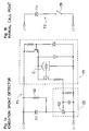
- Fig. 1a shows a schematic circuit diagram of a first known type (T1) of fire detecting device, which includes an ionisation chamber C for detecting smoke.
- T1 of detector a threshold voltage of a zener diode ZD1 is selected according to the parameter which is sensed, e.g. smoke, heat, flame or some other parameter.
- Fig. 1b is a circuit diagram of another type T2 of fire detecting device, i.e. a manual call point which includes a switch 3 in series with a zener diode ZD2. Both of these devices can be connected via terminals L1, L2 to a pair of supply lines 7 (shown in Fig. 2) to which is also connected a central control unit (CCU) 6, of conventional construction.
- CCU central control unit
- Each type T1,T2 of detecting device applies a high impedance across the supply lines 7 in a standby condition, but is responsive to a change in state, due to a fire condition, to apply a low impedance across the supply lines 7 in an alarm condition.
- the CCU 6 provides a current supply on the lines at a voltage which is higher than the threshold voltage of the zener diodes ZD1, ZD2, the supply being current limited by a resistor (not shown), or other means to prevent the power dissipation rating of the zener diodes being exceeded in an alarm condition.
- resistor 4 is shown connected in parallel with zener diode ZD1, so as to maintain thyristor 5 in a latched state, in the event that the supply voltage becomes less than the threshold voltage of the zener diode ZD1. This may occur when a second detecting device (not shown), connected to the same line 7 and having a slightly lower threshold voltage zener diode, also detects a fire.
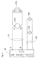
- Fig. 2 is a schematic diagram of a known fire detection and alarm system in which CCU 6 is shown connected via lines 7 to a first type of detecting device T1 (similar to that shown in Fig. 1a) and a second type of detecting device T2 (similar to that shown in Fig. 1b).
- Alarm devices 10 are shown connected to the CCU 6 by a second pair of supply lines 8.
- the CCU 6 includes voltage threshold sensing means (not shown) responsive to the voltage across lines 7, i.e. at points A and B, and switching means (not shown) responsive to the voltage threshold sensing means which activates the alarm devices 10 to produce an alert or evacuate warning, according to the voltage across lines 7, when a fire has been detected.
- the detecting devices T1, T2 provide different low impedances across the lines 7 which limit the voltage across lines 7 to different voltages determined by, for example, the use of zener diodes with different zener voltages in the detecting devices T1, T2.
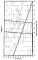
- Fig. 3 shows a known current/voltage characteristic 11 of the first type of detecting device T1 (e.g. a smoke detector). Characteristic 12 is that of a second type of detecting device T2 (e.g. a manual call point). These characteristics would be obtained when either device T1 or T2 is in an alarm condition. Fig. 3 also shows an example of a load-line characteristic of the output of the CCU to the fire detection devices. Characteristic 13 is that of a supply which is derived, for example, from a voltage source of 24 volts connected in series with a 600ohm resistor. In the alarm condition, the voltage across the supply and signalling lines is the voltage at which the characteristic of the fire detecting device intersects the CCU load-line.
- T1 e.g. a smoke detector
- Characteristic 12 is that of a second type of detecting device T2 (e.g. a manual call point). These characteristics would be obtained when either device T1 or T2 is in an alarm condition.
- Fig. 3 also shows an
- the voltage across A and B is 24 volts.
- the voltage across A and B is 15 volts and the CCU switches the alarm devices 10 to signal an "alert".
- the second type of detecting device T2 a manual call point
- the voltage across A and B is reduced to 10 volts and the CCU switches the alarm devices to signal "evacuate”.
- a disadvantage of the system described above is that separate lines are needed for fire detecting devices and alarm devices. This is because detecting devices in the alarm condition would be damaged by the high current available from the supply applied to the lines to operate alarm devices.
- a detecting device comprising signalling means for producing a change of state signal, from a quiescent state to an alarm state, when a change in condition or environment occurs, no such change normally occurring in the quiescent state.
- the detecting device also has impedance switching means with high and low impedance states which are applied across terminals for connection to supply lines.
- the impedance switching means is normally in a high impedance state when the signalling means is in its quiescent state, but responds to a change of state signal, from the signalling means, so as to switch to a low impedance state.
- the low impedance state increases current drain on the supply lines so that it is recognisable as a fire detection signal.
- the detecting device normally operates with a first voltage present on the supply lines. However, an alarm device is actuated when a second voltage, higher than the first voltage, is applied to the supply lines.
- the detecting device further includes voltage responsive means, which respond to the second voltage, to cause the impedance switching means to switch to a high impedance state, so that the line impedance across the supply line terminals is increased, so as to reduce current drain and thereby conserve power.
- the alarm device when the alarm condition exists, can be provided with a relatively high operating current at the second voltage, in order to give a fire warning, but the current drain by the detecting device is reduced to a minimum, to conserve available power. This is important when the power supply is a battery, because it can extend the life of the battery under the alarm condition.
- means are provided for generating an "alert" signal when a smoke detector is in an alarm condition, and an "evacuate” signal whenever a manual call point is in an alarm condition.
- a disadvantage of the means disclosed in the copending application is that the identification of the signal from a manual call point involves reversing the polarity of the voltage applied to the supply lines, thereby increasing CCU complexity and cost.
- a further disadvantage is that polarity must be observed when connecting smoke detectors to the supply lines and this can lead to errors during installation.
- a digital communications protocol is used by the fire detecting devices to signal to a CCU a code which identifies the type of detecting device that is transmitting a fire detection signal and a change of the parameter which is being monitored (e.g. smoke).
- the CCU in such a system can use the communications protocol to send signals to alarm devices which are activated according to the type of detector that has signalled the change in parameter being monitored.
- analogue addressable systems require more complex and more expensive electronics in detecting devices, alarm devices and the CCU, than in conventional, i.e. non-addressable systems which use conventional, non-addressable fire detecting devices, having only two or three operating states.
- the present invention provides a solution to this problem which has the advantage of simple and low-cost construction and which can also employ robust electronics in the circuitry of the fire detectors, alarm devices and CCU.
- a fire detection and alarm system comprises:
- the fire detecting devices are preferably latched in the alarm condition so that they continue to signal a fire despite any variation, such as a change in the monitored parameter or in supply line voltage.
- latching circuitry can be included in say a smoke detector (as described in our copending UK application 9808094.8)
- the concept of being latched applies also to a manual call point, e.g. where a button is pressed and stays in, thereby continuing to remain in a switching state that represents the alarm condition.
- the manual call point can be considered to be operable by the first voltage, since it requires a voltage to exceed the zener threshold and to provide a current drain in its low impedance state.
- the different types of detecting devices can include, for example, smoke detectors, flame detectors and manual call points.
- the first and second types of detecting device could be of generally similar construction, except for the respective current limiting means, since one may be used to monitor one environment where another could be used to monitor another environment. Therefore, the construction of the detecting device is relatively unimportant, as long as it provides a change from a high impedance to a low impedance condition as a result of being actuated from a standby to an alarm condition and its voltage responsive means enables it to be identified as one type or the other.
- the alarm means may be a single device which is capable of giving different kinds of fire warnings, but it can also be several alarm devices which give respective kinds of fire warnings. Also, there may be more than one alarm device giving the same kind of warning, for example, where it is necessary to generate an evacuate signal on each floor of a large building.
- the alarm means is initially operable at a second voltage which is higher than the first voltage so that it is not actuated unless and until an alarm condition exists. It may initially signal a priority condition, such as "evacuate", or a lower priority "alert”.
- the alarm means responds to operating current which is supplied, under different conditions, so as to give respectively different kinds of fire warnings.
- the voltage may be changed or the polarity of the current may be reversed in order to cause the alarm means to give a different kind of warning. Therefore, the condition under which operating current is supplied enables the alarm means to be actuated so as to give the required kind of fire warning.
- the fire warning may be a sound signal, such as a siren, bell or buzzer, and/or it may include a visual warning, such as flashing lights, and/or it may include verbal instructions for occupants of buildings to take appropriate action, such as evacuation, following a predetermined fire escape route, etc, and/or it may include telephoning the Fire Brigade.
- the CCU is preferable operable so as to cause the alarm means to operate so that priority is given to one of the types of fire detecting devices.
- the second type of fire detecting device is a manual call point
- this can be accorded priority over the first type, which may be a smoke detector.
- This can be achieved by enabling the CCU to detect a different voltage, e.g. when the line voltage is momentarily reduced to examine the voltage on the supply lines (the line voltage will differ due to the different zener diode thresholds, even where the first type is in the alarm state before the second type).
- giving priority may not be essential, since different types of warning could be given according to which type of detector is in the alarm state.
- the first type of detecting device could be, for example, a smoke detector which, when in the alarm condition, causes a timer to commence a countdown before an alarm signal is transmitted to fire fighting services.
- the second type of detecting device can be a manual call point which overrides the timer so as to cause an evacuate warning to be given without waiting for the end of the timed period.
- a fire detection and alarm system comprises a central control unit (CCU) connected to more than one type of fire detector and at least one alarm device by a pair of supply lines supplying operating current at a first voltage to the fire detectors and alarm devices, the supply lines being used to signal current drain in any fire detector as a fire detection signal, the fire detectors operating when a first voltage is present on the supply line and the alarm devices activating when a second voltage, which is higher than the first voltage is present on the supply lines; each type of detector including:
- first circuit means (Ref: Fig. 4, T9, T8, R15) for limiting the current drain of a fire detection signal over a first voltage range including the first voltage
- second circuit means (ZD3, R10, R11, T7) for reducing the current drain of the fire detection signal to a low value over a second voltage range, substantially contiguous with the first voltage range and including the second voltage
- third circuit means (ZD4, R13, T9) for reducing the current drain of the fire detection signal to a low value over a third voltage range substantially contiguous with the first voltage range and wherein all voltages in the third voltage range are lower than the lowest voltage in the first voltage range, characterised in that:
- the current drain of a fire signal from detectors of types other than the first type when supplied with a voltage equal to or close to the lowest voltage in the first voltage range of a fire detector of the first type, is less than one tenth of the current drain of a fire detector of the first type under the same supply voltage conditions, such that a fire signal from a detector of the first type can be recognised when ten or more detectors of any other type(s) simultaneously signal fire.
- detectors of the first type are manual call points.
- this is a circuit diagram of a fire detecting device which can be used in an embodiment of the invention.
- a detailed description of the circuitry is given in our copending UK application No. 9808094.8.
- the modification according to the present invention means that in detectors of the first type, the voltage threshold of zener diode ZD4 is made significantly less than the voltage threshold of the zener diode ZD4 in the second type of detector.
- the circuitry is generally the same, apart from the threshold voltage of the zener diode which characterises the detector type.
- Fig. 5 shows a typical current/voltage characteristic of fire detecting devices in an alarm condition. Characteristic 15 is that of a first type of detecting device and characteristic 16 is that of a second type of detecting device. Characteristic 17 shows a typical current/voltage load-line characteristic of a CCU in an embodiment of the invention, with a resistive internal impedance in series with a source voltage equal to the first voltage. Characteristic 18 shows a typical current/voltage load-line characteristic of a CCU in an embodiment of the invention with a substantially voltage independent current limiting means in series with a source voltage equal to the first voltage. In both cases the voltage developed across the supply lines is equal to the lowest voltage at which the CCU load-line intersects a detector characteristic, i.e. the intersection which drains the highest current. Fig. 5 also shows that the current drain in the alarm condition of both types of detecting device is within the 0.5watt power limit curve 19.
Landscapes
- Business, Economics & Management (AREA)
- Emergency Management (AREA)
- Physics & Mathematics (AREA)
- General Physics & Mathematics (AREA)
- Fire Alarms (AREA)
- Alarm Systems (AREA)
Applications Claiming Priority (2)
| Application Number | Priority Date | Filing Date | Title |
|---|---|---|---|
| GB9821189A GB2342204B (en) | 1998-09-30 | 1998-09-30 | Fire detection and alarm system with selective fire warning |
| GB9821189 | 1998-09-30 |
Publications (3)
| Publication Number | Publication Date |
|---|---|
| EP0991041A2 true EP0991041A2 (de) | 2000-04-05 |
| EP0991041A3 EP0991041A3 (de) | 2001-01-03 |
| EP0991041B1 EP0991041B1 (de) | 2003-11-26 |
Family
ID=10839673
Family Applications (1)
| Application Number | Title | Priority Date | Filing Date |
|---|---|---|---|
| EP99307532A Expired - Lifetime EP0991041B1 (de) | 1998-09-30 | 1999-09-23 | Branderkennung und Alarmsystem mit selektiver Bandwarnung |
Country Status (7)
| Country | Link |
|---|---|
| US (1) | US6133828A (de) |
| EP (1) | EP0991041B1 (de) |
| JP (1) | JP2000113342A (de) |
| AT (1) | ATE255261T1 (de) |
| DE (1) | DE69913077T2 (de) |
| ES (1) | ES2209345T3 (de) |
| GB (1) | GB2342204B (de) |
Cited By (1)
| Publication number | Priority date | Publication date | Assignee | Title |
|---|---|---|---|---|
| GB2553289B (en) * | 2016-08-24 | 2020-05-20 | Orisec Ltd | Alarm system detector |
Families Citing this family (3)
| Publication number | Priority date | Publication date | Assignee | Title |
|---|---|---|---|---|
| US8736444B2 (en) * | 2011-09-30 | 2014-05-27 | Tyco Fire & Security Gmbh | System and method for wireless heat detection |
| GB2500885B (en) * | 2012-04-02 | 2015-08-05 | Anthony Payn | Signalling system |
| ES3005091T3 (en) | 2021-04-05 | 2025-03-13 | Carrier Corp | Fire system with current response calibration |
Family Cites Families (7)
| Publication number | Priority date | Publication date | Assignee | Title |
|---|---|---|---|---|
| JPS6017157B2 (ja) * | 1981-02-25 | 1985-05-01 | ニツタン株式会社 | 選択作動可能な火災感知器 |
| US4812821A (en) * | 1987-04-24 | 1989-03-14 | Santy Michael J | Visual fire alert system |
| CH674113A5 (de) * | 1987-09-09 | 1990-04-30 | Willemin Electronic S A | |
| NO885320L (no) * | 1987-11-30 | 1989-05-31 | Hochiki Co | Brann-alarm system. |
| US5083107A (en) * | 1989-05-01 | 1992-01-21 | Nohmi Bosai Kabushiki Kaisha | Fire alarm system |
| US5670938A (en) * | 1991-01-18 | 1997-09-23 | Hochiki Kabushiki Kaisha | Fire alarm device |
| US5705979A (en) * | 1995-04-13 | 1998-01-06 | Tropaion Inc. | Smoke detector/alarm panel interface unit |
-
1998
- 1998-09-30 GB GB9821189A patent/GB2342204B/en not_active Expired - Lifetime
-
1999
- 1999-09-23 AT AT99307532T patent/ATE255261T1/de not_active IP Right Cessation
- 1999-09-23 ES ES99307532T patent/ES2209345T3/es not_active Expired - Lifetime
- 1999-09-23 DE DE69913077T patent/DE69913077T2/de not_active Expired - Fee Related
- 1999-09-23 EP EP99307532A patent/EP0991041B1/de not_active Expired - Lifetime
- 1999-09-29 US US09/408,976 patent/US6133828A/en not_active Expired - Fee Related
- 1999-09-30 JP JP11279958A patent/JP2000113342A/ja active Pending
Cited By (1)
| Publication number | Priority date | Publication date | Assignee | Title |
|---|---|---|---|---|
| GB2553289B (en) * | 2016-08-24 | 2020-05-20 | Orisec Ltd | Alarm system detector |
Also Published As
| Publication number | Publication date |
|---|---|
| US6133828A (en) | 2000-10-17 |
| ES2209345T3 (es) | 2004-06-16 |
| EP0991041A3 (de) | 2001-01-03 |
| GB2342204B (en) | 2003-05-07 |
| DE69913077D1 (de) | 2004-01-08 |
| DE69913077T2 (de) | 2004-08-26 |
| GB2342204A (en) | 2000-04-05 |
| GB9821189D0 (en) | 1998-11-25 |
| JP2000113342A (ja) | 2000-04-21 |
| ATE255261T1 (de) | 2003-12-15 |
| EP0991041B1 (de) | 2003-11-26 |
Similar Documents
| Publication | Publication Date | Title |
|---|---|---|
| EP1251473B1 (de) | Kommunikationssystem für Gefahrenmelder | |
| JP2857298B2 (ja) | 防災監視装置 | |
| US6353395B1 (en) | Interconnectable detector with local alarm indicator | |
| US6049446A (en) | Alarm systems and devices incorporating current limiting circuit | |
| EP0951001A2 (de) | Detektierungsvorrichtung und Alarmsystem | |
| JP2931734B2 (ja) | 防災監視装置 | |
| EP0991041B1 (de) | Branderkennung und Alarmsystem mit selektiver Bandwarnung | |
| US4477798A (en) | Fire Alarm control system | |
| EP0396386A2 (de) | Feueralarmsystem | |
| US4887072A (en) | Alarm apparatus | |
| JPH11185189A (ja) | 火災報知システム | |
| JP2854491B2 (ja) | 防災監視装置および方法 | |
| GB2065348A (en) | Multiple alarm condition detection and signalling | |
| EP0967585B1 (de) | Alarmanlage | |
| JPH01287799A (ja) | 火災報知装置 | |
| JP2802012B2 (ja) | 防災監視装置 | |
| JPH11154284A (ja) | 呼出発光チャイム | |
| JPH1164427A (ja) | 断線報知方法および装置 | |
| JP3203136B2 (ja) | ホームセキュリティ装置 | |
| JPS634239B2 (de) | ||
| JP3065339B2 (ja) | 火災報知設備における端末機器 | |
| JP2902258B2 (ja) | 防災監視装置 | |
| KR940007914B1 (ko) | 홈(home)안정 외부통보 제어장치 및 방법 | |
| JP3032278B2 (ja) | 火災報知設備における端末機器 | |
| JPH07296279A (ja) | 防災監視装置 |
Legal Events
| Date | Code | Title | Description |
|---|---|---|---|
| PUAI | Public reference made under article 153(3) epc to a published international application that has entered the european phase |
Free format text: ORIGINAL CODE: 0009012 |
|
| AK | Designated contracting states |
Kind code of ref document: A2 Designated state(s): AT BE CH CY DE DK ES FI FR GB GR IE IT LI LU MC NL PT SE |
|
| AX | Request for extension of the european patent |
Free format text: AL;LT;LV;MK;RO;SI |
|
| PUAL | Search report despatched |
Free format text: ORIGINAL CODE: 0009013 |
|
| AK | Designated contracting states |
Kind code of ref document: A3 Designated state(s): AT BE CH CY DE DK ES FI FR GB GR IE IT LI LU MC NL PT SE |
|
| AX | Request for extension of the european patent |
Free format text: AL;LT;LV;MK;RO;SI |
|
| 17P | Request for examination filed |
Effective date: 20010118 |
|
| AKX | Designation fees paid |
Free format text: AT BE CH CY DE DK ES FI FR GB GR IE IT LI LU MC NL PT SE |
|
| GRAH | Despatch of communication of intention to grant a patent |
Free format text: ORIGINAL CODE: EPIDOS IGRA |
|
| GRAS | Grant fee paid |
Free format text: ORIGINAL CODE: EPIDOSNIGR3 |
|
| GRAA | (expected) grant |
Free format text: ORIGINAL CODE: 0009210 |
|
| AK | Designated contracting states |
Kind code of ref document: B1 Designated state(s): AT BE CH CY DE DK ES FI FR GB GR IE IT LI LU MC NL PT SE |
|
| PG25 | Lapsed in a contracting state [announced via postgrant information from national office to epo] |
Ref country code: NL Free format text: LAPSE BECAUSE OF FAILURE TO SUBMIT A TRANSLATION OF THE DESCRIPTION OR TO PAY THE FEE WITHIN THE PRESCRIBED TIME-LIMIT Effective date: 20031126 Ref country code: FI Free format text: LAPSE BECAUSE OF FAILURE TO SUBMIT A TRANSLATION OF THE DESCRIPTION OR TO PAY THE FEE WITHIN THE PRESCRIBED TIME-LIMIT Effective date: 20031126 Ref country code: CY Free format text: LAPSE BECAUSE OF FAILURE TO SUBMIT A TRANSLATION OF THE DESCRIPTION OR TO PAY THE FEE WITHIN THE PRESCRIBED TIME-LIMIT Effective date: 20031126 Ref country code: BE Free format text: LAPSE BECAUSE OF FAILURE TO SUBMIT A TRANSLATION OF THE DESCRIPTION OR TO PAY THE FEE WITHIN THE PRESCRIBED TIME-LIMIT Effective date: 20031126 Ref country code: AT Free format text: LAPSE BECAUSE OF FAILURE TO SUBMIT A TRANSLATION OF THE DESCRIPTION OR TO PAY THE FEE WITHIN THE PRESCRIBED TIME-LIMIT Effective date: 20031126 |
|
| REG | Reference to a national code |
Ref country code: GB Ref legal event code: FG4D |
|
| REG | Reference to a national code |
Ref country code: CH Ref legal event code: EP |
|
| REF | Corresponds to: |
Ref document number: 69913077 Country of ref document: DE Date of ref document: 20040108 Kind code of ref document: P |
|
| REG | Reference to a national code |
Ref country code: IE Ref legal event code: FG4D |
|
| PG25 | Lapsed in a contracting state [announced via postgrant information from national office to epo] |
Ref country code: SE Free format text: LAPSE BECAUSE OF FAILURE TO SUBMIT A TRANSLATION OF THE DESCRIPTION OR TO PAY THE FEE WITHIN THE PRESCRIBED TIME-LIMIT Effective date: 20040226 Ref country code: GR Free format text: LAPSE BECAUSE OF FAILURE TO SUBMIT A TRANSLATION OF THE DESCRIPTION OR TO PAY THE FEE WITHIN THE PRESCRIBED TIME-LIMIT Effective date: 20040226 Ref country code: DK Free format text: LAPSE BECAUSE OF FAILURE TO SUBMIT A TRANSLATION OF THE DESCRIPTION OR TO PAY THE FEE WITHIN THE PRESCRIBED TIME-LIMIT Effective date: 20040226 |
|
| REG | Reference to a national code |
Ref country code: CH Ref legal event code: NV Representative=s name: ISLER & PEDRAZZINI AG |
|
| NLV1 | Nl: lapsed or annulled due to failure to fulfill the requirements of art. 29p and 29m of the patents act | ||
| REG | Reference to a national code |
Ref country code: ES Ref legal event code: FG2A Ref document number: 2209345 Country of ref document: ES Kind code of ref document: T3 |
|
| ET | Fr: translation filed | ||
| PG25 | Lapsed in a contracting state [announced via postgrant information from national office to epo] |
Ref country code: LU Free format text: LAPSE BECAUSE OF NON-PAYMENT OF DUE FEES Effective date: 20040923 Ref country code: IE Free format text: LAPSE BECAUSE OF NON-PAYMENT OF DUE FEES Effective date: 20040923 Ref country code: GB Free format text: LAPSE BECAUSE OF NON-PAYMENT OF DUE FEES Effective date: 20040923 |
|
| PG25 | Lapsed in a contracting state [announced via postgrant information from national office to epo] |
Ref country code: ES Free format text: LAPSE BECAUSE OF NON-PAYMENT OF DUE FEES Effective date: 20040924 |
|
| PG25 | Lapsed in a contracting state [announced via postgrant information from national office to epo] |
Ref country code: MC Free format text: LAPSE BECAUSE OF NON-PAYMENT OF DUE FEES Effective date: 20040930 Ref country code: LI Free format text: LAPSE BECAUSE OF NON-PAYMENT OF DUE FEES Effective date: 20040930 Ref country code: CH Free format text: LAPSE BECAUSE OF NON-PAYMENT OF DUE FEES Effective date: 20040930 |
|
| PLBE | No opposition filed within time limit |
Free format text: ORIGINAL CODE: 0009261 |
|
| STAA | Information on the status of an ep patent application or granted ep patent |
Free format text: STATUS: NO OPPOSITION FILED WITHIN TIME LIMIT |
|
| 26N | No opposition filed |
Effective date: 20040827 |
|
| PG25 | Lapsed in a contracting state [announced via postgrant information from national office to epo] |
Ref country code: DE Free format text: LAPSE BECAUSE OF NON-PAYMENT OF DUE FEES Effective date: 20050401 |
|
| GBPC | Gb: european patent ceased through non-payment of renewal fee |
Effective date: 20040923 |
|
| REG | Reference to a national code |
Ref country code: CH Ref legal event code: PL |
|
| PG25 | Lapsed in a contracting state [announced via postgrant information from national office to epo] |
Ref country code: FR Free format text: LAPSE BECAUSE OF NON-PAYMENT OF DUE FEES Effective date: 20050531 |
|
| REG | Reference to a national code |
Ref country code: IE Ref legal event code: MM4A |
|
| REG | Reference to a national code |
Ref country code: FR Ref legal event code: ST |
|
| PG25 | Lapsed in a contracting state [announced via postgrant information from national office to epo] |
Ref country code: IT Free format text: LAPSE BECAUSE OF NON-PAYMENT OF DUE FEES Effective date: 20050923 |
|
| REG | Reference to a national code |
Ref country code: ES Ref legal event code: FD2A Effective date: 20040924 |
|
| PG25 | Lapsed in a contracting state [announced via postgrant information from national office to epo] |
Ref country code: PT Free format text: LAPSE BECAUSE OF NON-PAYMENT OF DUE FEES Effective date: 20040426 |