EP0991071A2 - Aufzeichnungsmedium und Bandantriebsanordnung dafür - Google Patents
Aufzeichnungsmedium und Bandantriebsanordnung dafür Download PDFInfo
- Publication number
- EP0991071A2 EP0991071A2 EP99307687A EP99307687A EP0991071A2 EP 0991071 A2 EP0991071 A2 EP 0991071A2 EP 99307687 A EP99307687 A EP 99307687A EP 99307687 A EP99307687 A EP 99307687A EP 0991071 A2 EP0991071 A2 EP 0991071A2
- Authority
- EP
- European Patent Office
- Prior art keywords
- information
- tape
- partition
- memory
- mic
- Prior art date
- Legal status (The legal status is an assumption and is not a legal conclusion. Google has not performed a legal analysis and makes no representation as to the accuracy of the status listed.)
- Withdrawn
Links
Images





Classifications
-
- G—PHYSICS
- G11—INFORMATION STORAGE
- G11B—INFORMATION STORAGE BASED ON RELATIVE MOVEMENT BETWEEN RECORD CARRIER AND TRANSDUCER
- G11B23/00—Record carriers not specific to the method of recording or reproducing; Accessories, e.g. containers, specially adapted for co-operation with the recording or reproducing apparatus ; Intermediate mediums; Apparatus or processes specially adapted for their manufacture
- G11B23/02—Containers; Storing means both adapted to cooperate with the recording or reproducing means
- G11B23/04—Magazines; Cassettes for webs or filaments
- G11B23/041—Details
- G11B23/042—Auxiliary features
-
- G—PHYSICS
- G11—INFORMATION STORAGE
- G11B—INFORMATION STORAGE BASED ON RELATIVE MOVEMENT BETWEEN RECORD CARRIER AND TRANSDUCER
- G11B23/00—Record carriers not specific to the method of recording or reproducing; Accessories, e.g. containers, specially adapted for co-operation with the recording or reproducing apparatus ; Intermediate mediums; Apparatus or processes specially adapted for their manufacture
- G11B23/02—Containers; Storing means both adapted to cooperate with the recording or reproducing means
- G11B23/04—Magazines; Cassettes for webs or filaments
- G11B23/08—Magazines; Cassettes for webs or filaments for housing webs or filaments having two distinct ends
- G11B23/087—Magazines; Cassettes for webs or filaments for housing webs or filaments having two distinct ends using two different reels or cores
- G11B23/08707—Details
- G11B23/08714—Auxiliary features
-
- G—PHYSICS
- G11—INFORMATION STORAGE
- G11B—INFORMATION STORAGE BASED ON RELATIVE MOVEMENT BETWEEN RECORD CARRIER AND TRANSDUCER
- G11B27/00—Editing; Indexing; Addressing; Timing or synchronising; Monitoring; Measuring tape travel
- G11B27/10—Indexing; Addressing; Timing or synchronising; Measuring tape travel
- G11B27/102—Programmed access in sequence to addressed parts of tracks of operating record carriers
- G11B27/107—Programmed access in sequence to addressed parts of tracks of operating record carriers of operating tapes
-
- G—PHYSICS
- G11—INFORMATION STORAGE
- G11B—INFORMATION STORAGE BASED ON RELATIVE MOVEMENT BETWEEN RECORD CARRIER AND TRANSDUCER
- G11B27/00—Editing; Indexing; Addressing; Timing or synchronising; Monitoring; Measuring tape travel
- G11B27/10—Indexing; Addressing; Timing or synchronising; Measuring tape travel
- G11B27/11—Indexing; Addressing; Timing or synchronising; Measuring tape travel by using information not detectable on the record carrier
-
- G—PHYSICS
- G11—INFORMATION STORAGE
- G11B—INFORMATION STORAGE BASED ON RELATIVE MOVEMENT BETWEEN RECORD CARRIER AND TRANSDUCER
- G11B27/00—Editing; Indexing; Addressing; Timing or synchronising; Monitoring; Measuring tape travel
- G11B27/10—Indexing; Addressing; Timing or synchronising; Measuring tape travel
- G11B27/19—Indexing; Addressing; Timing or synchronising; Measuring tape travel by using information detectable on the record carrier
- G11B27/28—Indexing; Addressing; Timing or synchronising; Measuring tape travel by using information detectable on the record carrier by using information signals recorded by the same method as the main recording
- G11B27/32—Indexing; Addressing; Timing or synchronising; Measuring tape travel by using information detectable on the record carrier by using information signals recorded by the same method as the main recording on separate auxiliary tracks of the same or an auxiliary record carrier
- G11B27/327—Table of contents
- G11B27/328—Table of contents on a tape [TTOC]
-
- G—PHYSICS
- G11—INFORMATION STORAGE
- G11B—INFORMATION STORAGE BASED ON RELATIVE MOVEMENT BETWEEN RECORD CARRIER AND TRANSDUCER
- G11B15/00—Driving, starting or stopping record carriers of filamentary or web form; Driving both such record carriers and heads; Guiding such record carriers or containers therefor; Control thereof; Control of operating function
- G11B15/02—Control of operating function, e.g. switching from recording to reproducing
- G11B15/05—Control of operating function, e.g. switching from recording to reproducing by sensing features present on or derived from record carrier or container
- G11B15/06—Control of operating function, e.g. switching from recording to reproducing by sensing features present on or derived from record carrier or container by sensing auxiliary features on record carriers or containers, e.g. to stop machine near the end of a tape
- G11B15/07—Control of operating function, e.g. switching from recording to reproducing by sensing features present on or derived from record carrier or container by sensing auxiliary features on record carriers or containers, e.g. to stop machine near the end of a tape on containers
-
- G—PHYSICS
- G11—INFORMATION STORAGE
- G11B—INFORMATION STORAGE BASED ON RELATIVE MOVEMENT BETWEEN RECORD CARRIER AND TRANSDUCER
- G11B2220/00—Record carriers by type
- G11B2220/60—Solid state media
- G11B2220/65—Solid state media wherein solid state memory is used for storing indexing information or metadata
- G11B2220/652—Solid state media wherein solid state memory is used for storing indexing information or metadata said memory being attached to the recording medium
- G11B2220/655—Memory in cassette [MIC]
-
- G—PHYSICS
- G11—INFORMATION STORAGE
- G11B—INFORMATION STORAGE BASED ON RELATIVE MOVEMENT BETWEEN RECORD CARRIER AND TRANSDUCER
- G11B2220/00—Record carriers by type
- G11B2220/90—Tape-like record carriers
Definitions
- the present invention relates to a recording medium used for data storage, and a tape drive device suitable for a tape cassette serving as a recording medium.
- a so-called tape streamer drive is known as a drive device which can record/reproduce digital data in a magnetic tape.
- Such a tape streamer drive can have a large recording capacity of about several tens to several hundreds giga-bytes although it is dependent on the tape length of the tape cassette serving as media, and thus it is widely used to such an application as to back up data recorded in media such as a hard disc of the computer body or the like. Further, it is suitably used to preserve image data or the like which has a large data size.
- a tape streamer drive as described above has been proposed one which records/reproduces data by using a 8-mm VTR tape cassette as a recording medium and using a helical scan system based on a rotational head.
- the tape cassette described above contains a non-volatile memory comprising a memory IC.
- manufacturing information of a tape cassette, past use record information of the tape cassette, partition information of a magnetic tape, etc. are beforehand stored as management information in the non-volatile memory.
- management information By storing the management information in the non-volatile memory as described above, each of various operations can be more efficiently performed as compared with a case where management information is recorded in a specific area on a magnetic tape.
- the non-volatile memory When the tape cassette is initialized (formatted) to form partitions on the magnetic tape, the non-volatile memory is also initialized to store partition information corresponding to the partitions.
- the non-volatile memory When the non-volatile memory is initialized, it is necessary to grasp the storage capacity of the non-volatile memory. Therefore, when the tape cassette is initialized, it is necessary to first perform specific read-in processing/writing processing on the non-volatile memory to thereby search the address corresponding to the storage capacity.
- partition information on each partition to be formed is required to be stored in the non-volatile memory.
- a tape drive device comprising: tape drive means for recording or reproducing information into/from a magnetic tape when a tape cassette having the magnetic tape accommodated therein is loaded; memory drive means through which when a memory for recording management information to manage the recording or reproduction of information into/from the magnetic tape is provided to the tape cassette, the management information can be read out or written from/into the memory; means for detecting storage capacity information of the memory which is stored in the memory; and means for recognizing the storage capacity of the memory on the basis of the storage capacity information.
- the storage capacity information of the memory is stored in the memory.
- the storage capacity information of a memory can be detected from the memory (MIC) which is provided to a tape cassette and records management information to manage recording or reproduction to a magnetic tape accommodated in the tape cassette.
- MIC memory
- the storage capacity information of the memory is recorded as the management information in the memory (MIC) arranged together with the magnetic tape, so that the storage capacity of the memory can be grasped without searching the storage area of the memory at the drive device side.
- the assignee of this application previously proposed inventions on a tape cassette provided with a non-volatile memory and a tape drive device forming a data storage system which can record/reproduce digital data in connection with the tape cassette with the memory.
- the present invention is applied to a data storage system which corresponds to a tape cassette with a memory.
- the non-volatile memory provided to the tape cassette is assumed to be MIC (Memory In Cassette).
- Fig. 1 conceptually shows the internal construction of a tape cassette.
- Reel hubs 2A, 2B are provided in the tape cassette 1 shown in Fig. 1, and a magnetic tape 3 having a tape width of 8mm is wound between the reel hubs 2A and 2B.
- the tape cassette 1 is provided with MIC 4 which is a non-volatile memory, and five terminals 5A, 5B, 5C, 5D and 5E are extended from the module of MIC 4 and constructed as a data input terminal, a clock input terminal, an earth terminal, a preliminary terminal, respectively. Described in more detail later, In MIC 4 are stored information on a manufacturing date (year, month, date) and a manufacturing place of each tape cassette, the thickness, length and material of a tape, past use records of recording data of each partition formed on the tape 3, etc., user information, etc. In this specification, these various information to be stored in the MIC 4 is referred to as "management information".
- Fig. 2 shows the outlook of the tape cassette 1., and the overall housing thereof comprises an upper side case 6a, a lower side case 6b and a guard panel 8.
- the tape cassette 1 is basically designed in the same construction as a tape cassette used in a usual 8-mm VTR.
- Terminal pins 7A, 7B, 7C, 7D and 7E are provided on a label face at the side surface of the tape cassette 1, and these pins are connected to the terminals 5A, 5B, 5C, 5D, 5E respectively described with reference to Fig. 1. That is, in this embodiment, the tape cassette 1 is physically brought into contact with a tape streamer drive 10 described next through the terminal pins 7A, 7B, 7C, 7D, 7E to mutually transmit data signals, etc. therebetween.
- the tape streamer drive 10 is designed to record/reproduce the magnetic tape 3 of the loaded tape cassette 1 on the basis of a helical scan system.
- Two recording heads 12A and 12B having different azimuth angles and three reproducing heads 13A, 13B and 13C having desired azimuth angles are provided to a rotational drum 11 so as to be spaced at predetermined angular intervals.
- the rotational drum 11 around which the magnetic tape 3 drawn out from the tape cassette 1 is rotated by a drum motor 14A.
- a capstan (not shown) for making the magnetic tape 3 run at a constant speed is rotationally driven by a capstan motor 14B.
- the reel hubs 2A, 2B in the tape cassette 1 are independently rotated in a forward direction and in a reverse direction by reel motors 14C, 14D.
- a loading motor 14E rotates a loading mechanism (not shown) to execute a loading/unloading of the magnetic tape 3 into/from the rotational drum 11.
- the drum motor 14A, the capstan motor 14B, the reel motors 14C, 14D, the loading motor 14E are rotated by applying voltage from a mechanical driver 17 thereto.
- the mechanical driver 17 drives each motor under the control of a servo controller 16.
- the servo controller 16 controls the rotational speed of each motor to execute tape travelling in usual recording/reproducing operation, tape travelling in high-speed reproducing operation, a tape travelling in fast feeding, rewinding operation, a tape cassette loading operation, a loading/unloading operation, a tape tension control operation, etc.
- each of the drum motor 14A, the capstan motor 14B and the reel motors 14C, 14D is provided with FG (frequency generator) to detect rotational information of each motor.
- the servo controller 16 identifies the rotational speed of each motor on the basis of FG pulses of these FGs to detect an error from a target rotational speed for the rotational operation of each motor, and controls application of power corresponding to the error difference on the mechanical driver 17, thereby performing the rotational speed control based on close loop. Accordingly, in the normal travelling during the recording/reproducing operation or in various operations such as a high-speed search operation, a fast feeding operation, a rewinding operation, etc., the servo controller 16 can control each motor to rotate at a target rotational speed suitable for each of the operations.
- EEP-ROM 18 are stored constants, etc. which the servo controller 16 uses to perform servo control of each motor.
- the servo controller 16 is interactively connected to the system controller 15 which executes the control processing of the overall system through interface controller/ECC formatter 22 (hereinafter referred to as IF/ECC controller).
- IF/ECC controller interface controller/ECC formatter 22
- an SCSI interface 20 is used for input/output of data. For example, when data are recorded, sequential data are input from the host computer 40 through the SCSI interface 20 every fixed-length record serving as a transmission data unit, and supplied to a compression/expansion circuit 21. In such a table streamer drive system, there also exists a mode in which data are transmitted from the host computer 40 every assembly of data of variable length.
- input data are subjected to compression processing by a specific system, if necessary.
- the compression system for example if a compression system based on LZ code is used, in this system special-purpose codes are shared to a character sequence which was previously processed, and stored in a dictionary style. An input character sequence and the content of the dictionary are afterwards compared with each other, and if the character sequence of the input data is coincident with the code of the dictionary, the character sequence data are replaced by the code of the dictionary.
- the data of the input character sequence which is not coincident with the dictionary are sequentially supplied with a new code, and then registered in the dictionary. As described above, the data of the input character sequence are registered in the dictionary, and the character sequence data are replaced by the code of the dictionary, thereby performing the data compression.
- the output of the compression/expansion circuit 21 is supplied to the IF/ECC controller 22, and in the IF/ECC controller 22, the output of the compression/expansion circuit 21 is temporarily accumulated in a buffer memory 23 by the control-operation thereof. Under the control of the IF/ECC controller 22, the data accumulated in the buffer memory 23 are finally assembled every fixed-length unit corresponding to 40 tracks of a magnetic tape which is called as a group (Group). The data of each group are subjected to ECC format processing.
- recording data is added with an error correction code, subjected to modulation processing so as to be suitably magnetically recorded, and then supplied to an RF processor 19.
- the recording data thus supplied are subjected to processing of amplification, recording equalization, etc. to generate a recording signal, and then supplied to recording heads 12A, 12B, whereby the recording of the data from the recording heads 12A, 12B on the magnetic tape 3 is performed.
- the recording data of the magnetic tape 3 are read out as REF reproduction signals by reproducing heads 13a, 13B, and the reproduction outputs thereof are subjected to reproduction equalizing, reproduction clock generation, conversion to binary values, decoding (for example, Viterbi decoding), etc. in the RF processor 19.
- the signals thus read out are supplied to the IF/ECC controller 22, and first subjected to the error correction processing, etc. Then, the signals are temporarily accumulated in the buffer memory 23, read out at a predetermined time and supplied to the compression/expansion circuit 21.
- the compression/expansion circuit 21 On the basis of the judgment of the system controller 15, if the data are subjected to the compression by the compression/expansion circuit 21 in the recording operation, the data are subjected to the expansion processing. If the data are non-compression data, the data are directly output with performing no data expansion processing.
- the output data of the compression/expansion circuit 21 are output to the host computer 40 as reproduction data through the SCSI interface 20.
- Fig. 3 the magnetic tape 3 of the tape cassette 1 and MIC 4 are shown.
- the MIC 4 is connected to the system controller 15 through the terminal pin shown in Fig. 3 so that the data can be input/output therethrough, whereby the system controller 15 can read in and renew management information recorded in the MIC 4.
- the information is mutually transmitted between the tape streamer drive 10 and the host computer 40 by using the SCSI interface 20, and the host computer 40 can perform various kinds of communications with the system controller 15 by using the SCSI command.
- the host computer 40 instructs the system controller 15 with the SCSI command to execute the data write-in/read-out operation on the MIC 4.
- S-RAM 24 flash ROM 25 store data which the system controller 15 uses to perform various processing.
- S-RAM 24 is used as a work memory, or it is used as a memory used to store the data read out from the MIC 4, the data to be written in the MIC 4, mode data set every tape cassette, various flag data, etc. and perform operation processing.
- the S-RAM 24 and the flash ROM 25 may be constructed as an internal memory of a microcomputer constituting the system controller 15. Further, a part of the area of the buffer memory 23 may be used as a work memory.
- Figs. 4A to 4D shows the structure of the data recorded in the magnetic tape 3.
- Fig. 4A schematically shows one magnetic tape 3.
- one magnetic tape 3 can be used while divided on a partition (Partition) basis as shown in Fig. 4A, and in the case of the system of this embodiment, the number of partitions can be set to 256 at maximum for management. Further, the respective partitions as shown in this figure are managed while being supplied with partition numbers as written as partition #0, #1, #2, #3, etc.
- the data recording/reproduction, etc. can be performed independently every partition.
- the recording unit of data within one partition shown in Fig. 4B can be divided into units of fixed length which are called as groups (Group) shown in Fig. 4C, and the recording on the magnetic tape 3 can be performed on a group basis.
- one group corresponds to the data amount of 20 frames (Frame), and as shown in Fig. 4D, one frame is constructed by 2 tracks (Track). In this case, two tracks constituting one frame are set as plus azimuth and minus azimuth which are adjacent to each other. Accordingly, one group is constructed by 40 tracks.
- Fig. 5A shows the data structure of a block (Block) unit.
- One block is constructed by a 1-byte SYNC data area Al, a 6-byte ID area A2 which is subsequent to the 1-byte SYNC data area Al and used for search, etc., a 2-byte error correcting parity area A3 for ID data and a 64-byte data area A4.
- the data of one track shown in Fig. 5B is constructed by 471 blocks, As shown in the figure, one track is provided with margin areas All, A19 of 4 blocks at both ends thereof, and ATF areas A12, A18 for tracking control are provided at the rear side of the margin area All and at the front side of the margin A19. Further, parity areas A13, A17 are provided at the rear side of the ATF area A12 and at the front side of the ATF area A18. An area of 32 blocks is provided as each of the parity areas A13, A17.
- An ATF area A15 is provided in the middle of one track, and a 5-block area is provided to each of these ATF areas A13, A15 and A18.
- the data-recording is performed on the--magnetic tape 3 shown in Figs. 4, 5 on the basis of the area structure shown in Figs. 6A to 6C.
- the number of partitions is limited to N from #0 to #N-1.
- a leader tape is physically located at the head thereof, and subsequently a device area serving as a loading/unloading area of the tape cassette is provided.
- the head of the device area is set as the head position PBOT (Physical Beginning of Tape) of the physical tape.
- a reference area on the partition #0 and a system area in which past use record information of the tape, etc. are stored (hereinafter referred to as system area containing the reference area) is provided, and subsequently a data area is provided.
- the head of the system area is set as the start position LBOT (Logical Beginning of Tape) of the physical tape.
- a position tolerance band NO. 1 As shown in a large scale in Fig. 6C, in the sytem area are formed a reference area, a position tolerance band NO. 1, a system preamble, a system log, a system post-amble, a position tolerance band NO. 2, a vendor group preamble.
- a vendor group indicating information on a vendor which first creates and supplies-data is-provided, and subsequently a group shown in Fig. 4C, in this case, a plurality of groups represented by group 1 to group (n) are sequentially formed.
- An amble frame is disposed subsequently to the group (n).
- an area of EOD (End of Data) indicating the end of the data area of the partition is provided as shown in Fig. 6A.
- the end of EOD of the partition #0 is set as the end position LEOT (Logical End of Tape) of the logical tape.
- LEOT Logical End of Tape
- partitions of N are formed, and thus an optional device area is formed subsequently to EOD of the partition #0.
- the device area from the head position PBOT is an area for performing the load/unload corresponding to the partition #0, however, the final optional device area of the partition #0 becomes an area for performing the load/unload corresponding to the partition #1.
- an area is constructed as in the case of the partition #0.
- an optional device area serving as an area for performing the load/unload corresponding to the next partition #2.
- partitions until the partition # (N-1) are formed likewise.
- any optional device area is not required and thus no optional device area is formed.
- the end of EOD of the-partition #(N-1) is set as the end position LEOT (Logical end of Tape) of the logical tape.
- PEOT Physical End of Tape indicates the end position of the physical tape, or the physical end position of the partition.
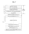
- Fig. 7 schematically shows an example of the structure of data stored in MIC 4.
- Fields FL1 to FL6 are set as a storage area of MIC 4.
- the field FL1 is set as a manufacture part, and various information at the time of manufacturing the tape cassette is mainly stored therein.
- the field FL2 is set as a drive initialize part, and information at the initialization time, etc. are stored therein.
- the field FL3 is set as a volute information, and basic management information of the overall tape cassette is stored therein.
- the field FL4 is set as an accumulative partition information, and past record information from the manufacturing time of the tape cassette is stored therein.
- each information is stored as a volume tag.
- the field FL6 is set as a memory free pool area, and management information can be additionally stored.
- the process of the recording/reproducing operation, and if necessary, various information are stored in the memory free pool.
- One unit data group to be stored in the memory free pool is referred to as "cell".
- partition information cells #0, #1, ... serving as the management information corresponding to each partition are successively written from the head side of the memory free pool. That is, the partition information cells are formed as cells whose number is equal to that of the partitions formed on the magnetic tape 3.
- Absolute volume map information cell serving as map information for high-speed search is written from the rear end side of the memory free pool.
- the user volume note cell is information such as comment, etc. which are input on the overall tape cassette by a user
- the user partition note is information-such as a comment, etc. which are input on each partition by the user. Accordingly, these are stored when the user instructs the write-in operation, and all of these information is not necessarily described.
- the manufacture part of the field FL1 is structured as shown in Fig. 8, for example.
- the size of each data is shown at the right side.
- manufacture part information of checksum for the data of the manufacture part is stored as manufacture part checksum at the head of 1 byte.
- the information of the manufacture part checksum is given at the manufacturing time of the cassette.
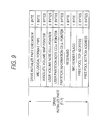
- Data from MIC type (mic type) to a write protect byte count are described as real data constituting the manufacture part. Reserve indicates a preliminary area for storing data in the future. The same is satisfied in Figs. 9 to 13.
- a MIC type is data indicating the type of MIC which is really provided to the tape cassette.
- a MIC manufacture date indicates the manufacture year, month and date (and time).
- a MIC manufacture line name indicates information on the name of a manufacturing line for MIC.
- a MIC manufacture plant name indicates the information on the name of a factory in which MIC is manufactured.
- a MIC manufacturer name indicates the information on a manufacturing company of MIC.
- a MIC name indicates the information on the name of a vendor of MIC.
- the information of the cassette itself which is similar to the information on MIC described above is described in each of a cassette manufacture date, a cassette manufacture line name, a cassette manufacture plant name, a cassette manufacturer name, a cassette name.
- OEM customer name is stored information on the name of a partner company of OEM (Original Equipment Manufactures).
- a physical tape characteristic ID is indicated the information on physical characteristics of a magnetic tape such as the material of the tape, the tape thickness, the tape length, etc.
- the maximum clock frequency is stored the information indicating the maximum clock frequency corresponding to the MIC.
- a maximum write byte count/cycle information as to what bytes can be recorded once is indicated as the characteristics of MIC, for example. This information is dependent on the physical characteristics of a non-volatile memory used as MIC.
- a write protect top address is used to prohibit writing into a desired partial area of MIC, and indicates the start address of the writing-prohibited area.
- a write protect byte count indicates the number of bytes in the writing-prohibited area. That is, an area which is occupied from an address indicated by the write protect top address on the basis of the byte number indicated by the area of the write protect count is set as a writing-prohibited area.
- the ID number of a logical format of MIC is stored as the MIC logical format type.
- the MIC format exist not only a basic MIC format, but also various formats relevant to a firmware renewing tape MIC format, a reference tape MIC format, a cleaning cassette MIC format, etc., and the ID number corresponding to the MIC format of the tape cassette concerned is indicated.
- a point indicating the head address of the area of an absolute volume map information cell of Fig. 7 is disposed in an absolute volume map pointer.
- a user volume note cell pointer indicates a storage area in which data are freely readable and writable via SCSI, that is, the start address of the user volume note cell shown in Fig. 7.
- a user partition note cell pointer indicates a storage area which data can be freely read/written from/into each partition via SCSI by a user, that is, the start address of the user partition note cell of Fig. 7.
- the user partition note cell pointer indicates the start address of the head cell of the plural user partition note cells.
- the partition information cell pointer indicates the start address of the partition information cell #0 of Fig. 7.
- partition information pieces to be written into the memory free pool the number of which corresponds to the number of partitions to be formed in the magnetic tape 3.
- All the partition information cells #0 to #N are linked to one another on the basis of a link structure by a pointer. That is, the partition information cell pointer is set as a route indicating the address of the partition #0, and a pointer of a subsequent partition information cell is disposed in a just-before partition information cell-. This link structure will be described later with reference to Figs. 14, 15.
- each data position within the field FL6 is managed by each pointer (absolute volume map pointer, user volume note cell pointer, user partition note cell pointer, partition information cell pointer).
- An MIC header flag is set to an 1-byte flag to supply a logical writing-prohibiting tab to MIC 4. That is, the content indicated by the MIC header flag includes write-in permission/prohibition of the manufacture part potion, or write-in permission/prohibition of a portion other than the manufacture part.
- the free pool top address and the free pool bottom address indicate the start address and the end address of the memory free pool at that time in the field FL6.
- the area as the memory free pool is varied in accordance with the writing or deletion of the partition information, the user partition note or the like, so that the free pool top address or the free pool bottom address is renewed.
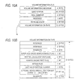
- information of checksum for the data of the volume information is stored as the volume information checksum at the head of 1 byte.
- volume information As real data constituting the volume information are described an eject status of 20 bytes, a reel diameter of 4 bytes, an initialize count of 3 bytes, and a volume information on tape of 72 bytes.
- the eject status describes the logical position information of the magnetic tape 3 when the tape cassette is unloaded, and the reel diameter indicates the diameter information of both the reel hubs 2A, 2B at the time when the tape cassette is unloaded.
- the initialize count indicates frequency information of initialization of the magnetic tape 3.
- the content of the volume information on tape is shown in Fig. 10B.
- a 1-bit super high speed search enable flag As shown in Fig. 10B, in the volume information on tape are described, except for an area serving as reserve, a 1-bit super high speed search enable flag, a 2-bit system log allocation flag, a 1-bit always unload PBOT flag, a 1-byte AIT/DDS flag, a 1-byte last valid partition number, and a 32-byte optional device area allocation map.
- the super high speed search enable flag is a flag indicating whether a function of further increasing the speed of the high-speed search is made effective or not by using the table position information stored as the absolute volume map of MIC 4.
- the system log allocation flag is a flag indicating where the past use record of the tape cassette (system log) is stored, and it is designed to identify whether the past user record is recorded only on the magnetic tape 3, neither in the magnetic tape 3 nor in the MIC 4, both in the magnetic tape 3 and in MIC 4, or only in the MIC 4.
- the always unload PBOT flag is a flag indicating that even when a multipartition is formed on the magnetic tape 3 and the optional device area exists in the partition, unload is carried out in the device area existing in PBOT.
- the AIT/DDS flag is a flag indicating the mode of the tape cassette 1.
- the last valid partition number indicates the number of the last partition formed.
- the optional device area map comprises 256 bits, and 1 bit corresponds to each partition formed on the magnetic tape 3.
- 1 bit corresponds to each partition formed on the magnetic tape 3.
- the partition information cell, the user partition note cell, etc. are stored in the field FL 6.
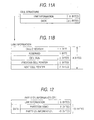
- one cell comprises 8-byte link information and data of n bytes (varied in accordance with the cell type).
- 1-byte cell checksum is provided as checksum on data within a cell.
- the size of the cell is shown as the cell size of 2 bytes.
- a previous cell pointer and a next cell pointer are actual linkage data (data for constructing the link structure), and when a plurality of same types of cells are linked, previous and next cells are indicated by the previous cell pointer and the next cell pointer.
- the partition information cell As the cell having such a structure exist the partition information cell, the absolute volume map information cell, the user volume note cell and the user partition note cell.
- the cell size of the partition information is a fixed value.
- the cell size of the other cells is of a variable value.
- the partition information cell comprises 8-byte link information and 56-byte data as shown in Fig. 12. 8 bytes out of the 56-byte data are allocated as a partition memo, and 48 bytes are allocated as partition information.
- the data structure of the partition information within one partition information cell which corresponds to some partition is defined as shown in Fig. 13, for example.
- the value of the area thereof is incremented in accordance with the number of groups to be newly recorded by the current recording operation through the processing of the system controller 15 of the tape streamer drive.
- a total rewritten frames of 3 bytes indicates an accumulation value of the number of frames for which rewriting is requested on the basis of READ-AFTER-WRITE (hereinafter abbreviated as RAW) in the partition concerned.
- RAW READ-AFTER-WRITE
- the data of a frame which is written in the magnetic tape 3 as RAW operation are read out by the reproducing head 13C just after.
- the data of a frame read out by RAW are subjected to error detection by the system controller 15, and when it is detected that an error occurs, the recording system is controlled to rewrite the data of a frame in which the error occurs.
- the accumulation value of the number of frames which are subjected to data rewriting is set as a total rewritten frame.
- the error correction is conducted on data read out from the magnetic tape 3 by parities of C1, C2, C3, and the C3 parity is used when the data cannot be restored by only the cl, C2 parities.
- a frequency at which the partition concerned on the magnetic tape is accessed by the tape streamer drive In an access count of 4 bytes is indicated a frequency at which the partition concerned on the magnetic tape is accessed by the tape streamer drive.
- the access of this case means a physically passing frequency of the partition concerned, that is, the frequency at which the recording or reproduction of the partition is performed and the passing frequency are contained.
- prevent write prevent read, prevent write retry, prevent read retry are prepared write permission/prohibition and read permission/prohibition for the partition concerned, data rewriting permission/prohibition based on RAW in the recording operation, and retry permission/prohibition of data read-out in the reproducing operation, respectively.
- partition-is-opened is prepared a flag which is set during recording in the partition concerned and reset in accordance with the end of the recording.
- each pointer in the field FL2 absolute volume map pointer, user volume note cell pointer, user partition note cell pointer, partition information cell pointer.
- the partition information cells #0 to #3 are stored in the field FL6 as shown in Fig. 14.
- the absolute volume map information cell, the user volume note cell and the user partition note cells #0, #2, #3 are stored in the field FL6 as shown in the figure.
- the head addresses of the respective partition information cells #0 to #3 are set to ad1, ad2, ad3, ad4 as shown in the figure.
- the head address of the absolute volume map information cell is set to ad11; the head address of the user volume cell is set to ad10; and the head addresses of the respective user partition note cells #0, #2 and #3 are set to ad9, ad8 and ad7, respectively.
- the head address as the remaining memory free pool is set to ad5
- the rear end address thereof is set to ad6.
- the value of the absolute volume map pointer within the field FL2 is set to "ad11", and the position as the absolute volume map information cell within the field FL6 is managed.
- the value of the user volume note cell pointer within the field FL2 is set to "ad10", thereby managing the position of the user volume note cell within the field FL6.
- the position of the head cell thereof is indicated by a pointer in the field FL2.
- the value of the partition information cell pointer within the field FL is set to "ad1" to indicate the position of the first partition information cell #0 within the field FL6.
- the value of the user partition note cell pointer within the field FL2 is set to "ad9" to indicate the position of the first user partition note cell #0 within the field FL6.
- the second and subsequent partition information cells #1 to #3 which are not indicated by the partition information cell pointer, and the second and subsequent user partition note cells #2 and #3 which are not indicated by the user partition note cell pointer are managed by linking previous and next cells to each other on the basis of the link information within each cell as described above.
- NP next cell pointer and the previous cell pointer described with reference to Figs. 11A and 11B.
- Fig. 15A shows the link configuration of the partition cell information cell.
- the next cell pointer NP ad2
- the next cell pointer NP of the partition information cell #1 is set to ad3, thereby indicating the position of the next partition information cell #2.
- the next cell pointer NP of the partition information cell #2 is set to ad4, thereby indicating the position of the next partition information cell #3.
- the next cell pointer NP is set to 0 (NO LINK) because any next cell to be linked does not exist.
- the previous cell pointer PP is set to "ad3", thereby indicating the position of the just-before partition information cell #2.
- the previous cell pointer PP is set to "ad2", thereby indicating the just-before partition information cell #1.
- the previous cell pointer PP is set to "ad1", thereby indicating the position of the just-before partition information cell #0.
- the respective partition information cells are managed while previous and next cells are linked to each other by the next cell pointer and the previous cell pointer.
- Fig. 15B shows the link configuration of the user partition note cell.
- the next cell pointer is set to ad8, thereby indicating the position of the next user partition note cell #2.
- the next cell pointer NP of the user partition note cell #2 is set to ad7, thereby indicating the position of the next user partition note cell #3.
- the next cell pointer NP is set to 0 (NO LINK) because any next cell to be linked does not exist.
- the previous cell pointer PP is set to "ad8", thereby indicating the position of the just-before user partition note cell #2.
- the previous cell pointer PP is set to "ad9", thereby indicating the just-before user partition note cell #0.
- the respective user partition note cells are managed while previous and next cells are linked to each other by the next cell pointer and the previous cell pointer.
- the address thereof is managed by the pointer in the field FL2, and when plural cells are linked, previous and next cells can be grasped by the link information.
- the link structure is constructed as described above to manage each cell, thereby enabling cell addition, renewal, etc. For example, addition or deletion of a partition on the magnetic tape 3 follows addition or deletion of a partition information cell, and at this time the cell structure is renewed while the link configuration constructed by the pointers and the link information is traced.
- the data structure within MIC 4 is constructed as described with reference to Figs. 7 to 15.
- this data structure of MIC 4 is an example, and the arrangement of data, the area setting, the data content, the data size, etc. are not limited to the above example.
- Fig. 16 shows a state of MIC 14 in which the tape cassette 1 is not formatted by the tape streamer drive 10.
- the MIC header portion fields FL1 to FL5
- Fig. 7 in MIC 4 desired initial data are stored.
- the field FL6 all are set as memory free pool (additionally writable area).
- the head address "#S" of the memory free pool subsequent to the MIC header portion is fixed, and the end address "#E” of the field FL6 corresponds to the free pool bottom address on the basis of the storage capacity of MIC 4.
- the head address "#S” corresponds to the free pool top address
- the end address "#E” corresponds to the free pool bottom address. That is, the end address "#E” is set to the value corresponding to the storage capacity of MIC 4 indicated in a MIC capacity as described later.
- the overall MIC 4 is accessed to perform the address search in order to detect the end address "#E" before the tape cassette 1 is formatted, for example.
- the address search it is necessary to access (read, write) MIC 4 at plural times, and a processing load as preprocessing of the formatting is large.
- the storage capacity of the MIC 4 concerned can be recognized on the basis of the storage capacity information indicated in the MIC capacity of the manufacture part (field FL1) of the MIC header.
- the end address "#E" of the field FL6 based on the storage capacity of MIC 4 which is recognized from the MIC capacity can be set as an initial value of the free pool bottom address.
- the storage capacity of the overall MIC 4 can be identified without performing the address search of the overall MIC 4. Accordingly, the access processing such as the address search which has been conventionally performed can be omitted, and the shift to the format processing of MIC 4 can be quickly performed.
- Fig. 17 The state of MIC 4 after the format is carried out is shown -in Fig. 17. In the case shown in Fig. 17, it is assumed that three partitions are set to execute the format and partitions #0, #1, #2 are formed on the magnetic tape 3.
- the partition information cells #0, #1, #2 corresponding to the partitions #0, #1, #2 are stored from the head side of the field FL6. Further, the absolute volume map information cells are written from the rear end side of the field FL6, whereby the free pool top address and the free pool bottom address are renewed.
- the end address "#E" of the field FL6 based on the storage capacity of MIC 4 is set as an initial value of the free pool bottom address.
- the storage capacity of MIC 4 can be detected from the MIC capacity, so that the number of partition information cells which can be formed on the basis of the storage capacity can be grasped. That is, at the time when the MIC capacity is detected (before the format is started), the number of partitions which can be formed on the magnetic tape 3 of the tape cassette 1 concerned can be grasped.
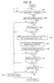
- Fig 18 is a flowchart showing a transition example of the processing which is executed by the system controller 15 when the tape cassette 1 is formatted.
- the check of MIC 4 is to read in the manufacture part or drive initialize part to identify, by desired judging process, whether the MIC 4 includes an error/errors and whether the MIC 4 is provided to the tape cassette concerned.
- the flowchart of this embodiment shows a shift case to the format under the state that MIC 4 is provided and further no error is detected.
- the processing waits until a desired format command is supplied from a host computer 40 (S001).
- a partition number (the number of partitions to be formed) indicated by the format command is checked (S002).
- the MIC capacity within the field FL1 which is detected by MIC check at the loading time, it can be immediately checked whether the partitions whose number is indicated by the format command can be formed.
- the free pool top address, the free pool bottom address and the MIC capacity are read from MIC 4 again (S006).
- the free pool top address and the free pool bottom address are set (S007).
- the drive initialize part in the MIC header is initialized (S008), and when the result of the initialization is "OK" (s009), MIC 4 is initialized by writing desired system data (partition information, accumulative partition information, absolute volume map information) (S010).
- steps S003, S005, S009, S011, S013 is judged as "NO", occurrence of an error is regarded, and at that time a desired error code is set (S015) and the format processing is finished.
- the partition number check is performed in the step S002, and if the number of partitions to be formed is larger with respect to the storage capacity of MIC 4, the format is finished under the state that the desired-error code is set. In this case, the partition number is re-set to a small number in connection with the storage capacity of MIC 4, whereby the format of the tape cassette 1 can be executed.
- the number of partitions which can be formed on the magnetic tape 3 of the tape cassette 1 can be known at the time when the storage capacity of MIC 4 is detected. Therefore, this partition number is set as a restriction value, and it can be supplied to the host computer 40, for example. Before the partition number is set from the host computer 40 side, it may be indicated how many partitions can be formed on the tape cassette 1.
Landscapes
- Management Or Editing Of Information On Record Carriers (AREA)
- Signal Processing For Digital Recording And Reproducing (AREA)
- Indexing, Searching, Synchronizing, And The Amount Of Synchronization Travel Of Record Carriers (AREA)
Applications Claiming Priority (2)
| Application Number | Priority Date | Filing Date | Title |
|---|---|---|---|
| JP27826798 | 1998-09-30 | ||
| JP10278267A JP2000113640A (ja) | 1998-09-30 | 1998-09-30 | テープドライブ装置、記録媒体 |
Publications (2)
| Publication Number | Publication Date |
|---|---|
| EP0991071A2 true EP0991071A2 (de) | 2000-04-05 |
| EP0991071A3 EP0991071A3 (de) | 2001-07-11 |
Family
ID=17594971
Family Applications (1)
| Application Number | Title | Priority Date | Filing Date |
|---|---|---|---|
| EP99307687A Withdrawn EP0991071A3 (de) | 1998-09-30 | 1999-09-29 | Aufzeichnungsmedium und Bandantriebsanordnung dafür |
Country Status (3)
| Country | Link |
|---|---|
| US (1) | US6501612B1 (de) |
| EP (1) | EP0991071A3 (de) |
| JP (1) | JP2000113640A (de) |
Cited By (5)
| Publication number | Priority date | Publication date | Assignee | Title |
|---|---|---|---|---|
| US6702215B2 (en) | 2002-07-03 | 2004-03-09 | Quantum Corporation | Repositionable memory element in a single reel tape cartridge |
| EP1498901A1 (de) * | 2003-07-18 | 2005-01-19 | Quantum Corporation | Methode und System, um vorausschauende und präventive Wartung und/oder Fehlereingrenzung in einem Bandspeichgerät zu gewährleisten |
| EP1017057B1 (de) * | 1998-12-02 | 2006-09-20 | Sony Corporation | Bandantriebseinrichtung |
| US7177108B2 (en) | 2003-06-03 | 2007-02-13 | Quantum Corporation | Emulation of auxiliary memory |
| EP1647986A4 (de) * | 2003-07-23 | 2007-08-22 | Pioneer Corp | Einmalbeschreibbares aufzeichnungsmedium, recorder und aufzeichnungsverfahren für ein einmalbeschreibbares aufzeichnungsmedium, wiedergabevorrichtung und wiedergabeverfahren für ein einmalbeschreibbares aufzeichnungsmedium, computerprogramm zur steuerung des aufzeichnens und der wiedergabe und datenstruktur |
Families Citing this family (8)
| Publication number | Priority date | Publication date | Assignee | Title |
|---|---|---|---|---|
| US6781782B2 (en) | 2000-12-21 | 2004-08-24 | Iomega Corporation | Method and apparatus for saving calibration parameters for a removable cartridge |
| US6779067B2 (en) | 2001-05-14 | 2004-08-17 | Iomega Corporation | Method and apparatus for providing extended functionality for a bus |
| US6901525B2 (en) | 2001-05-25 | 2005-05-31 | Iomega Corporation | Method and apparatus for managing power consumption on a bus |
| US6775087B2 (en) * | 2001-06-18 | 2004-08-10 | Sony Corporation | Method and apparatus to read past EOD marker |
| US6804075B1 (en) | 2002-03-01 | 2004-10-12 | Sony Corporation | Logical expiration of media having embedded non-volatile memory |
| US20040004789A1 (en) * | 2002-07-03 | 2004-01-08 | Christopher Watanabe | Replaceable memory element in a single reel tape cartridge |
| US20050152670A1 (en) * | 2004-01-14 | 2005-07-14 | Quantum Corporation | Auxiliary memory in a tape cartridge |
| US20070136517A1 (en) * | 2005-11-29 | 2007-06-14 | Quantum Corporation | Use of directory revision number to validate directory |
Family Cites Families (8)
| Publication number | Priority date | Publication date | Assignee | Title |
|---|---|---|---|---|
| DE69434627T2 (de) | 1993-09-30 | 2006-09-07 | Sony Corp. | Kassetten mit Speichern |
| US6101070A (en) * | 1993-09-30 | 2000-08-08 | Sony Corporation | Method and apparatus for determining information and a cassette for use therewith |
| US5852534A (en) * | 1995-06-30 | 1998-12-22 | Sony Corporation | Tape cassette, tape recording apparatus and tape reproducing apparatus |
| JPH09171676A (ja) | 1995-12-20 | 1997-06-30 | Sony Corp | データ記録/再生方法 |
| AU726982B2 (en) | 1996-12-25 | 2000-11-30 | Sony Corporation | Recording/reproduction apparatus, recording/reproduction method, input/output apparatus, input/output method, storage apparatus, transmission apparatus, information processing apparatus and information processing method |
| US6182191B1 (en) * | 1997-02-27 | 2001-01-30 | Sony Precision Technology Inc. | Recording and reproducing system |
| JP4694660B2 (ja) | 1998-08-04 | 2011-06-08 | ソニー株式会社 | 記録媒体制御方法、記録媒体対応装置 |
| JP4061727B2 (ja) | 1998-08-14 | 2008-03-19 | ソニー株式会社 | テープドライブ装置 |
-
1998
- 1998-09-30 JP JP10278267A patent/JP2000113640A/ja active Pending
-
1999
- 1999-09-28 US US09/407,197 patent/US6501612B1/en not_active Expired - Lifetime
- 1999-09-29 EP EP99307687A patent/EP0991071A3/de not_active Withdrawn
Cited By (8)
| Publication number | Priority date | Publication date | Assignee | Title |
|---|---|---|---|---|
| EP1017057B1 (de) * | 1998-12-02 | 2006-09-20 | Sony Corporation | Bandantriebseinrichtung |
| US6702215B2 (en) | 2002-07-03 | 2004-03-09 | Quantum Corporation | Repositionable memory element in a single reel tape cartridge |
| US7177108B2 (en) | 2003-06-03 | 2007-02-13 | Quantum Corporation | Emulation of auxiliary memory |
| EP1498901A1 (de) * | 2003-07-18 | 2005-01-19 | Quantum Corporation | Methode und System, um vorausschauende und präventive Wartung und/oder Fehlereingrenzung in einem Bandspeichgerät zu gewährleisten |
| US7277246B2 (en) | 2003-07-18 | 2007-10-02 | Quantum Corporation | Methods and systems for providing predictive maintenance, preventative maintenance, and/or failure isolation in a tape storage subsystem |
| EP1647986A4 (de) * | 2003-07-23 | 2007-08-22 | Pioneer Corp | Einmalbeschreibbares aufzeichnungsmedium, recorder und aufzeichnungsverfahren für ein einmalbeschreibbares aufzeichnungsmedium, wiedergabevorrichtung und wiedergabeverfahren für ein einmalbeschreibbares aufzeichnungsmedium, computerprogramm zur steuerung des aufzeichnens und der wiedergabe und datenstruktur |
| US7656762B2 (en) | 2003-07-23 | 2010-02-02 | Pioneer Corporation | Write once recording medium, recorder and recording method for write once recording medium, reproducer and reproducing method for write once recording medium, computer program for controlling recording or reproduction, and data structure |
| US7869318B2 (en) | 2003-07-23 | 2011-01-11 | Pioneer Corporation | Write once recording medium, recorder and recording method for write once recording medium, reproducer and reproducing method for write once recording medium, computer program for controlling recording or reproduction, and data structure |
Also Published As
| Publication number | Publication date |
|---|---|
| JP2000113640A (ja) | 2000-04-21 |
| US6501612B1 (en) | 2002-12-31 |
| EP0991071A3 (de) | 2001-07-11 |
Similar Documents
| Publication | Publication Date | Title |
|---|---|---|
| JP3994532B2 (ja) | テープドライブ装置 | |
| JP4672824B2 (ja) | テープドライブ装置、記録媒体 | |
| WO2000038188A1 (en) | Recording medium, tape drive, and method for identifying type of recording medium | |
| US6501612B1 (en) | Recording medium and tape drive suitable for the same | |
| US6535344B1 (en) | Tape drive unit and recording medium | |
| JP4099886B2 (ja) | 記録媒体及びテープドライブ装置 | |
| US6603624B1 (en) | Tape drive unit and recording medium | |
| US6580576B1 (en) | Tape driving apparatus and recording medium | |
| JP4061727B2 (ja) | テープドライブ装置 | |
| US6624959B1 (en) | Tape driving apparatus and recording medium | |
| JP3525615B2 (ja) | テープカセット、デジタルデータ記録装置、及びデジタルデータ再生装置 | |
| US6621650B1 (en) | Recording medium and tape driving apparatus | |
| US6570729B1 (en) | Recording medium and tape drive apparatus that calculates available partition recording area using maximum frame number information stored in a memory-in-cassette | |
| EP1017057B1 (de) | Bandantriebseinrichtung | |
| JP3777613B2 (ja) | 情報記録再生装置 | |
| JP2000187905A (ja) | テープドライブ装置、記録媒体 | |
| JPH1131376A (ja) | 情報記録再生装置及び方法 | |
| JP4151124B2 (ja) | テープドライブ装置、記録媒体 | |
| JP2000076020A (ja) | テープドライブ方法、テープドライブ装置 | |
| JP2000113653A (ja) | テープドライブ装置、記録媒体 | |
| JP2000173241A (ja) | 記録媒体及びテープドライブ装置 | |
| JP2000090641A (ja) | 記録媒体及びテープドライブ装置 | |
| JP2000100151A (ja) | テープドライブ装置 | |
| JP4766085B2 (ja) | テープドライブ装置、記録媒体、及び記録再生方法 | |
| JP2000090640A (ja) | テープドライブ方法、テープドライブ装置 |
Legal Events
| Date | Code | Title | Description |
|---|---|---|---|
| PUAI | Public reference made under article 153(3) epc to a published international application that has entered the european phase |
Free format text: ORIGINAL CODE: 0009012 |
|
| AK | Designated contracting states |
Kind code of ref document: A2 Designated state(s): DE FR GB |
|
| AX | Request for extension of the european patent |
Free format text: AL;LT;LV;MK;RO;SI |
|
| PUAL | Search report despatched |
Free format text: ORIGINAL CODE: 0009013 |
|
| AK | Designated contracting states |
Kind code of ref document: A3 Designated state(s): AT BE CH CY DE DK ES FI FR GB GR IE IT LI LU MC NL PT SE |
|
| AX | Request for extension of the european patent |
Free format text: AL;LT;LV;MK;RO;SI |
|
| 17P | Request for examination filed |
Effective date: 20011227 |
|
| AKX | Designation fees paid |
Free format text: DE FR GB |
|
| 17Q | First examination report despatched |
Effective date: 20060316 |
|
| STAA | Information on the status of an ep patent application or granted ep patent |
Free format text: STATUS: THE APPLICATION IS DEEMED TO BE WITHDRAWN |
|
| 18D | Application deemed to be withdrawn |
Effective date: 20090708 |