EP0991105B1 - Kathodenstrahlröhre - Google Patents
Kathodenstrahlröhre Download PDFInfo
- Publication number
- EP0991105B1 EP0991105B1 EP99302509A EP99302509A EP0991105B1 EP 0991105 B1 EP0991105 B1 EP 0991105B1 EP 99302509 A EP99302509 A EP 99302509A EP 99302509 A EP99302509 A EP 99302509A EP 0991105 B1 EP0991105 B1 EP 0991105B1
- Authority
- EP
- European Patent Office
- Prior art keywords
- contour
- cathode ray
- ray tube
- funnel
- cross
- Prior art date
- Legal status (The legal status is an assumption and is not a legal conclusion. Google has not performed a legal analysis and makes no representation as to the accuracy of the status listed.)
- Expired - Lifetime
Links
- OAICVXFJPJFONN-UHFFFAOYSA-N Phosphorus Chemical compound [P] OAICVXFJPJFONN-UHFFFAOYSA-N 0.000 claims description 8
- 238000010894 electron beam technology Methods 0.000 description 23
- 230000007423 decrease Effects 0.000 description 4
- 238000009125 cardiac resynchronization therapy Methods 0.000 description 3
- 238000012986 modification Methods 0.000 description 2
- 230000004048 modification Effects 0.000 description 2
- 239000003086 colorant Substances 0.000 description 1
- 239000000463 material Substances 0.000 description 1
- 230000002093 peripheral effect Effects 0.000 description 1
Images


Classifications
-
- H—ELECTRICITY
- H01—ELECTRIC ELEMENTS
- H01J—ELECTRIC DISCHARGE TUBES OR DISCHARGE LAMPS
- H01J9/00—Apparatus or processes specially adapted for the manufacture, installation, removal, maintenance of electric discharge tubes, discharge lamps, or parts thereof; Recovery of material from discharge tubes or lamps
- H01J9/24—Manufacture or joining of vessels, leading-in conductors or bases
-
- H—ELECTRICITY
- H01—ELECTRIC ELEMENTS
- H01J—ELECTRIC DISCHARGE TUBES OR DISCHARGE LAMPS
- H01J29/00—Details of cathode-ray tubes or of electron-beam tubes of the types covered by group H01J31/00
- H01J29/86—Vessels; Containers; Vacuum locks
- H01J29/861—Vessels or containers characterised by the form or the structure thereof
-
- H—ELECTRICITY
- H01—ELECTRIC ELEMENTS
- H01J—ELECTRIC DISCHARGE TUBES OR DISCHARGE LAMPS
- H01J2229/00—Details of cathode ray tubes or electron beam tubes
- H01J2229/86—Vessels and containers
- H01J2229/8603—Neck or cone portions of the CRT vessel
- H01J2229/8606—Neck or cone portions of the CRT vessel characterised by the shape
- H01J2229/8609—Non circular cross-sections
Definitions
- the present invention relates to a cathode ray tube (CRT) and more particularly, to a cathode ray tube capable of reducing the power consumption and preventing deflection magnetic fields from leaking to the outside of the cathode ray tube.
- CTR cathode ray tube
- a CRT is a device for displaying image on a screen by vertically and horizontally deflecting electron beams generated from an electron gun and landing the deflected electron beams onto the phosphor layers formed on the screen.
- the deflection of the electron beam is controlled by a deflection yoke mounted on an exterior surface of a funnel of the CRT and which forms vertical and horizontal magnetic fields.
- the CRTs are generally employed for color televisions (TVs), monitors and high definition televisions(HDTV). And with the increasing use of the CRTs, there is a need to reduce the length of the CRT for increasing the brightness of the displayed image and for reducing the size of the final products, such as TVs, monitors and HDTVs.
- the electron beams When reducing the length of the CRT, the electron beams should be deflected with wide-angles, and the deflection frequency and current supplied to the deflection yoke should be increased for the wide-angle deflections of the electron beams. As the deflection frequency and current increases, the deflection magnetic field tends to leak to the outside of the cathode ray tube and the power consumption increases.
- a compensation coil is generally mounted with the deflection yoke.
- the compensation coil is employed, the power consumption of the cathode ray tube more increases.
- U.S. patent No. 3,731,129 discloses a funnel having a wider peripheral portion sealed to the periphery of the panel, and a deflection portion whose cross-sectional configuration gradually varies from a rectangular shape substantially similar to that of the rectangular image produced on the panel to a circular shape.
- the vertical and horizontal coils of the deflection yoke are closely located to the passage of the electron beams, and deflect the electron beams with reduced deflection power and without bombarding the electron beams to the inner wall of the funnel.
- the deflection magnetic fields generated by the deflection yoke can not effectively deflect the electron beams, and the power consumption and the deflection magnetic field leakage can not be minimized.
- Japanese Laid Open Patent Pyung 9-320492 discloses the funnel, whose cross section of the exterior surface at the neck side is changed from a circular shape to a non-circular shape which has a maximum diameter along a direction (diagonal direction) other than the horizontal axis and the vertical axis. The angle between the diagonal direction and the horizontal axis is changed according to the distance from the electron gun.
- the Japanese Patent discloses that the CRT having the funnel can reduce the deflection power and the magnetic field leakage by mounting the deflection yoke at the nearest position to the passages of the electron beams.
- the exterior shape of the funnel on which the deflection yoke is mounted is designed without precisely considering the passages of the electron beams and the S-value (i.e. a distance between though holes of electron gun through which electron beams pass) by which the convergence and focusing characteristics of the electron beams are changed. Therefore, the deflection power and the deflection magnetic field leakage can not be effectively minimized.
- the present invention is directed to a cathode ray tube having advantages over known cathode ray tubes.
- a cathode ray tube comprising a face panel with a phosphor screen, a neck region in which an electron gun assembly is disposed, and a funnel region comprising a body portion and a cone portion wherein a contour of the cross section of said cone portion varies from a circular shape at said neck region to a non-circular shape at said funnel region such that the maximum perpendicular distance from the tube axis to the contour occurs substantially in the direction of a diagonal of the contour and which diagonal makes an angle ⁇ ' with respect to the horizontal axis according to the following inequality ⁇ - ⁇ 4.3 + (S/3.8) ⁇ ⁇ ⁇ ' ⁇ ⁇ + ⁇ 4.3 + (S/3.8) ⁇ wherein ⁇ is the angle in degrees that a diagonal of the face panel makes with respect to the horizontal axis; and S is the distance in mm between the centres of the electron passing holes of the electron gun assembly.
- the present invention can provide for a cathode ray tube capable of minimizing the power consumption and preventing deflection magnetic fields from leaking to the outside of the cathode ray tube.
- the invention can provide a cathode ray tube having a funnel whose exterior surface is designed similar to the passage of the electron beams. Also, the invention advantageously provides a cathode ray tube particularly suitable for flat-panel cathode ray tube.
- the present invention can provide for a cathode ray tube which includes a rectangular face panel on which a phosphor screen is formed, a neck in which an electron gun assembly for emitting three electron beams is disposed, and a funnel.
- the funnel which is comprised of a body portion and cone portion wherein a contour of the cross section of said cone portion varies from a circular shape at said neck region to a non-circular shape at said funnel region such that the maximum perpendicular distance from the tube axis to the contour occurs substantially in the direction of a diagonal of the contour which makes an angle ⁇ with respect to the horizontal axis according to the following inequality ⁇ - ⁇ 4.3 + (S/3.8) ⁇ ⁇ ⁇ ' ⁇ ⁇ + ⁇ 4.3 + (S/3.8) ⁇ wherein ⁇ is the angle in degree a diagonal of the face panel makes with respect to the horizontal axis; S is the distance in mm between the centres of the electron passing holes of the electron gun assembly.
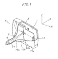
- a CRT is a vacuumed envelope having a substantially rectangular face panel 3, a funnel 7 and a cylindrical neck 11.
- the face panel 3 has a phosphor layer 1 coated on its inner surface. It has a predetermined aspect ratio.
- a deflection yoke 5 is mounted on a portion of the funnel 7 near the neck 11 and an electron gun assembly 9 for emitting three electron beams is disposed in the neck 11.
- the three electron beams emitted from the electron gun assembly 9 are horizontally and vertically deflected by horizontal and vertical magnetic fields generated by the deflection yoke 5 and pass apertures 13a in a shadow mask 13 mounted on the inner surface of the face panel 3 before hitting the phosphor layer 1, which as the result, emits lights of different colors depending on the phosphor material used.
- the funnel 7 is comprised of two rather distinct portions, a cone portion 70b and a body portion 70c, which are contiguously formed.
- the deflection yoke 5 is mounted on the cone portion 70b.
- the present invention lies in particular dimensional shapes of the cone portion 70b as described below.
- the cone portion 70b has a circular cross section at the point 70a where the cone portion is contiguously connected to the neck portion.
- the cross sectional shape of the cone gradually changes from circular to non-circular as they are taken toward the funnel body.
- the perpendicular distance from the central axis of the tube to the contour of the cross section is greatest in substantially diagonal direction because the cross sections would look more like a rectangle as they are nearer to the funnel body.
- a cone portion having gradually rectangular cross sections has an advantage of bringing the deflection magnetic fields generated from the deflection yoke 5 closer to the passages of the electron beams.
- Fig. 3 illustrates a superposed cross-sections, marked by "a” and "b" of the cone portion at the point 70a where the cone portion starts and at the point where the cone portion ends respectively.
- the cone portion 70b is designed such that the maximum distance from the tube axis to the contour of the cross section occurs in a substantially diagonal direction.
- the tube axis is an axis passing the centers of the face panel 3 and the neck 11.
- the cone portion 70b can be defined by the following, which represents an angle ⁇ ' the substantially diagonal of the non-circular cross section makes with respect to the horizontal axis. ⁇ - 4.3 + S / 3.8 ⁇ ⁇ ⁇ ⁇ + ⁇ 4.3 + S / 3.8 ⁇ wherein ⁇ is the angle in degree the diagonal of the face panel makes with respect to the horizontal axis;
- S is the distance in mm between the centers of the electron passing holes of the electron guns.
- Fig. 4 shows a cross sectional view of a cone portion 70b in the first quadrant according to the present invention.
- the contour of the cross section can be considered as having three curvatures serially connected.
- the first curvature C/Al represents the side of the contour and second curvature C/As represents the top of the contour.
- the third curvature C/Ad is located between the first and second curvature as illustrated in the figure. More particularly, the third curvature should be present within the angle ⁇ ' between ⁇ - ⁇ 4.3 + (S/3.8) ⁇ and ⁇ + ⁇ 4.3+(S/3.8) ⁇ .
- the substantially diagonal axis of the cross section of the cone portion 70b is located within ⁇ ⁇ 4.3 + (S/3.8) ⁇ to the face panel's diagonal angle ⁇ the deflection power consumption is reduce.
- the interior surface of the cone portion 70b preferably follows a similar configuration.
- the interior contour of the cross section of the cone portion 70b also gradually changes from a circular at the neck to non-circular or substantially rectangular, to be specific, such that the maximum distance from the tube axis to the inner contour of the cross section occurs in a substantially diagonal direction.
Landscapes
- Engineering & Computer Science (AREA)
- Manufacturing & Machinery (AREA)
- Vessels, Lead-In Wires, Accessory Apparatuses For Cathode-Ray Tubes (AREA)
Claims (3)
- Eine Katodenstrahlröhre, die Folgendes umfasst:eine Frontplatte (3) mit einem Leuchtschirm (1);einen Halsbereich (11), in dem eine Elektronenkanone (9) angeordnet ist; undeinen Trichterbereich (7), der einen Gehäuseanteil (70c) und einen Kegelanteil (70b) umfasst, wobei eine Querschnittskontour des Kegelanteils zwischen einer runden Form im Halsbereich und einer nicht runden Form im Trichterbereich variiert, dadurch gekennzeichnet dass der maximale senkrechte Abstand von der Röhrenachse bis zur Kontour im Wesentlichen in der Richtung einer Diagonale der Kontour erfolgt, wobei die Diagonale einen Winkel von θ' in Bezug auf die horizontale Achse gemäß folgender Ungleichung bildetwobei θ der Winkel in Grad ist, den eine Diagonale der Frontplatte (3) in Bezug auf die horizontale Achse bildet; und

S der Abstand in mm zwischen den Zentren des Elektrons ist, das die Löcher der Elektronenkanone passiert. - Eine Katodenstrahlröhre nach Anspruch 1, wobei die Kontour die äußere Kontour des Querschnitts ist.
- Eine Katodenstrahlröhre nach Anspruch 2, wobei die Kontour die innere Kontour des Querschnitts ist.
Applications Claiming Priority (2)
| Application Number | Priority Date | Filing Date | Title |
|---|---|---|---|
| KR1019980041356A KR100286587B1 (ko) | 1998-10-01 | 1998-10-01 | 음극선관 |
| KR9841356 | 1998-10-01 |
Publications (3)
| Publication Number | Publication Date |
|---|---|
| EP0991105A2 EP0991105A2 (de) | 2000-04-05 |
| EP0991105A3 EP0991105A3 (de) | 2003-07-30 |
| EP0991105B1 true EP0991105B1 (de) | 2007-02-21 |
Family
ID=19552934
Family Applications (1)
| Application Number | Title | Priority Date | Filing Date |
|---|---|---|---|
| EP99302509A Expired - Lifetime EP0991105B1 (de) | 1998-10-01 | 1999-03-30 | Kathodenstrahlröhre |
Country Status (7)
| Country | Link |
|---|---|
| US (1) | US6335588B1 (de) |
| EP (1) | EP0991105B1 (de) |
| JP (1) | JP2000113840A (de) |
| KR (1) | KR100286587B1 (de) |
| CN (1) | CN1145187C (de) |
| BR (1) | BR9900944A (de) |
| TW (1) | TW434630B (de) |
Families Citing this family (7)
| Publication number | Priority date | Publication date | Assignee | Title |
|---|---|---|---|---|
| JP2001325898A (ja) * | 2000-05-15 | 2001-11-22 | Matsushita Electric Ind Co Ltd | 陰極線管用ガラスバルブ及び陰極線管装置 |
| JP2002270116A (ja) * | 2001-03-14 | 2002-09-20 | Nippon Electric Glass Co Ltd | 陰極線管用ファンネル |
| JP3539635B2 (ja) * | 2001-04-17 | 2004-07-07 | 日本電気硝子株式会社 | 陰極線管用ファンネル |
| JP2006049145A (ja) | 2004-08-05 | 2006-02-16 | Matsushita Toshiba Picture Display Co Ltd | カラー受像管 |
| JP2006059574A (ja) * | 2004-08-17 | 2006-03-02 | Matsushita Toshiba Picture Display Co Ltd | カラー受像管 |
| US7242137B2 (en) | 2004-09-30 | 2007-07-10 | Matsushita Toshiba Picture Display Co., Ltd. | Cathode ray tube with cone having non-circular cross-section |
| US20060087215A1 (en) * | 2004-10-22 | 2006-04-27 | Matsushita Toshiba Picture Display Co., Ltd. | Cathode ray tube |
Family Cites Families (3)
| Publication number | Priority date | Publication date | Assignee | Title |
|---|---|---|---|---|
| JPS4834349B1 (de) * | 1969-11-04 | 1973-10-20 | ||
| JPH09306388A (ja) * | 1996-05-14 | 1997-11-28 | Toshiba Corp | 陰極線管 |
| JP3415361B2 (ja) * | 1996-05-28 | 2003-06-09 | 株式会社東芝 | 陰極線管 |
-
1998
- 1998-10-01 KR KR1019980041356A patent/KR100286587B1/ko not_active Expired - Fee Related
-
1999
- 1999-03-23 JP JP11076980A patent/JP2000113840A/ja active Pending
- 1999-03-29 TW TW088104939A patent/TW434630B/zh not_active IP Right Cessation
- 1999-03-30 EP EP99302509A patent/EP0991105B1/de not_active Expired - Lifetime
- 1999-04-06 US US09/287,594 patent/US6335588B1/en not_active Expired - Fee Related
- 1999-04-15 BR BR9900944-7A patent/BR9900944A/pt not_active IP Right Cessation
- 1999-05-10 CN CNB991063600A patent/CN1145187C/zh not_active Expired - Fee Related
Also Published As
| Publication number | Publication date |
|---|---|
| TW434630B (en) | 2001-05-16 |
| KR20000024705A (ko) | 2000-05-06 |
| JP2000113840A (ja) | 2000-04-21 |
| EP0991105A2 (de) | 2000-04-05 |
| CN1250221A (zh) | 2000-04-12 |
| KR100286587B1 (ko) | 2001-04-16 |
| CN1145187C (zh) | 2004-04-07 |
| EP0991105A3 (de) | 2003-07-30 |
| BR9900944A (pt) | 2000-05-30 |
| US6335588B1 (en) | 2002-01-01 |
Similar Documents
| Publication | Publication Date | Title |
|---|---|---|
| EP0810627B1 (de) | Kathodenstrahltröhre | |
| EP0813224B1 (de) | Ablenkjoch enthaltende Kathodenstrahlröhre mit verbesserter Trichterformgebung | |
| EP0886297B1 (de) | Kathodenstrahlröhre | |
| EP0833364B1 (de) | Kathodenstrahlröhre | |
| KR100315534B1 (ko) | 개선된 펀넬을 구비한 컬러 수상관 | |
| EP0991105B1 (de) | Kathodenstrahlröhre | |
| US5155411A (en) | Color CRT assembly having an improved envelope | |
| EP0993018B1 (de) | Kathodenstrahlröhre | |
| US6188173B1 (en) | Cathode ray tube | |
| US6396204B1 (en) | Cathode ray tube with enhanced beam deflection efficiency and minimized deflection power | |
| US6528936B1 (en) | Cathode ray tube with funnel cone thickness variations | |
| US6255766B1 (en) | Cathode ray tube with convex interior walls for added stability | |
| EP0634772B1 (de) | Farbkathodenstrahlröhre mit vermindertem Halo | |
| JP2000113832A (ja) | 陰極線管 | |
| US20030076058A1 (en) | Color cathode ray tube apparatus | |
| KR19990029672A (ko) | 개선된 내부자기시일드를 가지는 컬러음극선관 | |
| MXPA99003548A (es) | Tubo de rayos catodicos | |
| KR200248216Y1 (ko) | 음극선관을 이용한 화상 표시 장치 | |
| US7355331B2 (en) | Cathode-ray tube apparatus | |
| KR100316102B1 (ko) | 칼라음극선관용 전자총 지지체 | |
| US7501748B2 (en) | CRT funnel section | |
| KR200143460Y1 (ko) | 음극선관의 평향 요크 고정용 쐐기 | |
| JPH0638149U (ja) | ドット・タイプのカラー陰極線管用偏向ヨーク装置 | |
| KR19990030196U (ko) | 편향요크 | |
| MXPA99003546A (es) | Tubo de rayos catodicos |
Legal Events
| Date | Code | Title | Description |
|---|---|---|---|
| PUAI | Public reference made under article 153(3) epc to a published international application that has entered the european phase |
Free format text: ORIGINAL CODE: 0009012 |
|
| AK | Designated contracting states |
Kind code of ref document: A2 Designated state(s): AT BE CH CY DE DK ES FI FR GB GR IE IT LI LU MC NL PT SE |
|
| AX | Request for extension of the european patent |
Free format text: AL;LT;LV;MK;RO;SI |
|
| PUAL | Search report despatched |
Free format text: ORIGINAL CODE: 0009013 |
|
| AK | Designated contracting states |
Designated state(s): AT BE CH CY DE DK ES FI FR GB GR IE IT LI LU MC NL PT SE |
|
| AX | Request for extension of the european patent |
Extension state: AL LT LV MK RO SI |
|
| 17P | Request for examination filed |
Effective date: 20031229 |
|
| AKX | Designation fees paid |
Designated state(s): FR GB NL |
|
| REG | Reference to a national code |
Ref country code: DE Ref legal event code: 8566 |
|
| 17Q | First examination report despatched |
Effective date: 20050602 |
|
| GRAP | Despatch of communication of intention to grant a patent |
Free format text: ORIGINAL CODE: EPIDOSNIGR1 |
|
| GRAS | Grant fee paid |
Free format text: ORIGINAL CODE: EPIDOSNIGR3 |
|
| GRAA | (expected) grant |
Free format text: ORIGINAL CODE: 0009210 |
|
| AK | Designated contracting states |
Kind code of ref document: B1 Designated state(s): FR GB NL |
|
| REG | Reference to a national code |
Ref country code: GB Ref legal event code: FG4D |
|
| ET | Fr: translation filed | ||
| PLBE | No opposition filed within time limit |
Free format text: ORIGINAL CODE: 0009261 |
|
| STAA | Information on the status of an ep patent application or granted ep patent |
Free format text: STATUS: NO OPPOSITION FILED WITHIN TIME LIMIT |
|
| 26N | No opposition filed |
Effective date: 20071122 |
|
| PGFP | Annual fee paid to national office [announced via postgrant information from national office to epo] |
Ref country code: FR Payment date: 20100324 Year of fee payment: 12 |
|
| PGFP | Annual fee paid to national office [announced via postgrant information from national office to epo] |
Ref country code: GB Payment date: 20100322 Year of fee payment: 12 |
|
| PGFP | Annual fee paid to national office [announced via postgrant information from national office to epo] |
Ref country code: NL Payment date: 20100304 Year of fee payment: 12 |
|
| REG | Reference to a national code |
Ref country code: NL Ref legal event code: V1 Effective date: 20111001 |
|
| GBPC | Gb: european patent ceased through non-payment of renewal fee |
Effective date: 20110330 |
|
| REG | Reference to a national code |
Ref country code: FR Ref legal event code: ST Effective date: 20111130 |
|
| PG25 | Lapsed in a contracting state [announced via postgrant information from national office to epo] |
Ref country code: FR Free format text: LAPSE BECAUSE OF NON-PAYMENT OF DUE FEES Effective date: 20110331 Ref country code: NL Free format text: LAPSE BECAUSE OF NON-PAYMENT OF DUE FEES Effective date: 20111001 |
|
| PG25 | Lapsed in a contracting state [announced via postgrant information from national office to epo] |
Ref country code: GB Free format text: LAPSE BECAUSE OF NON-PAYMENT OF DUE FEES Effective date: 20110330 |