EP0991601B1 - Verfahren und vorrichtung zum zerfasern von mineralwolle durch freies zentrifugieren - Google Patents
Verfahren und vorrichtung zum zerfasern von mineralwolle durch freies zentrifugieren Download PDFInfo
- Publication number
- EP0991601B1 EP0991601B1 EP99915810A EP99915810A EP0991601B1 EP 0991601 B1 EP0991601 B1 EP 0991601B1 EP 99915810 A EP99915810 A EP 99915810A EP 99915810 A EP99915810 A EP 99915810A EP 0991601 B1 EP0991601 B1 EP 0991601B1
- Authority
- EP
- European Patent Office
- Prior art keywords
- wheel
- machine
- machines
- wheels
- angle
- Prior art date
- Legal status (The legal status is an assumption and is not a legal conclusion. Google has not performed a legal analysis and makes no representation as to the accuracy of the status listed.)
- Expired - Lifetime
Links
- 238000000034 method Methods 0.000 title claims description 18
- 239000011490 mineral wool Substances 0.000 title 1
- 238000007664 blowing Methods 0.000 claims description 22
- 239000000463 material Substances 0.000 claims description 22
- 239000012768 molten material Substances 0.000 claims description 15
- 230000002093 peripheral effect Effects 0.000 claims description 12
- 230000008569 process Effects 0.000 claims description 12
- 230000000694 effects Effects 0.000 claims description 11
- 238000004519 manufacturing process Methods 0.000 claims description 9
- 229910052500 inorganic mineral Inorganic materials 0.000 claims description 7
- 239000011707 mineral Substances 0.000 claims description 7
- 238000005304 joining Methods 0.000 claims description 3
- 239000000835 fiber Substances 0.000 description 60
- 238000005119 centrifugation Methods 0.000 description 22
- 238000012681 fiber drawing Methods 0.000 description 10
- 239000000047 product Substances 0.000 description 9
- 230000015572 biosynthetic process Effects 0.000 description 8
- 239000002657 fibrous material Substances 0.000 description 8
- 238000001816 cooling Methods 0.000 description 6
- 238000009826 distribution Methods 0.000 description 5
- 238000005259 measurement Methods 0.000 description 5
- 230000032258 transport Effects 0.000 description 5
- 239000002557 mineral fiber Substances 0.000 description 4
- 210000000056 organ Anatomy 0.000 description 4
- 238000009987 spinning Methods 0.000 description 4
- 239000012467 final product Substances 0.000 description 3
- 230000003993 interaction Effects 0.000 description 3
- 238000012423 maintenance Methods 0.000 description 3
- 230000002441 reversible effect Effects 0.000 description 3
- XLYOFNOQVPJJNP-UHFFFAOYSA-N water Substances O XLYOFNOQVPJJNP-UHFFFAOYSA-N 0.000 description 3
- 238000009825 accumulation Methods 0.000 description 2
- 239000011230 binding agent Substances 0.000 description 2
- 239000011521 glass Substances 0.000 description 2
- 238000002844 melting Methods 0.000 description 2
- 230000008018 melting Effects 0.000 description 2
- 230000002829 reductive effect Effects 0.000 description 2
- 101100495270 Caenorhabditis elegans cdc-26 gene Proteins 0.000 description 1
- 241000005139 Lycium andersonii Species 0.000 description 1
- 230000009471 action Effects 0.000 description 1
- 230000002411 adverse Effects 0.000 description 1
- 238000004873 anchoring Methods 0.000 description 1
- 230000008859 change Effects 0.000 description 1
- 208000027744 congestion Diseases 0.000 description 1
- 230000003247 decreasing effect Effects 0.000 description 1
- 230000007547 defect Effects 0.000 description 1
- 230000001627 detrimental effect Effects 0.000 description 1
- 238000011161 development Methods 0.000 description 1
- 238000010586 diagram Methods 0.000 description 1
- 230000002349 favourable effect Effects 0.000 description 1
- 239000008187 granular material Substances 0.000 description 1
- 238000000265 homogenisation Methods 0.000 description 1
- 239000012943 hotmelt Substances 0.000 description 1
- 230000006872 improvement Effects 0.000 description 1
- 238000009434 installation Methods 0.000 description 1
- 238000009413 insulation Methods 0.000 description 1
- 239000012212 insulator Substances 0.000 description 1
- 238000004599 local-density approximation Methods 0.000 description 1
- 239000000155 melt Substances 0.000 description 1
- 239000008267 milk Substances 0.000 description 1
- 210000004080 milk Anatomy 0.000 description 1
- 235000013336 milk Nutrition 0.000 description 1
- 230000003287 optical effect Effects 0.000 description 1
- 238000006116 polymerization reaction Methods 0.000 description 1
- 230000000750 progressive effect Effects 0.000 description 1
- 230000000284 resting effect Effects 0.000 description 1
- 238000005096 rolling process Methods 0.000 description 1
- 239000002893 slag Substances 0.000 description 1
- 238000012360 testing method Methods 0.000 description 1
- 238000012549 training Methods 0.000 description 1
Images

Classifications
-
- C—CHEMISTRY; METALLURGY
- C03—GLASS; MINERAL OR SLAG WOOL
- C03B—MANUFACTURE, SHAPING, OR SUPPLEMENTARY PROCESSES
- C03B37/00—Manufacture or treatment of flakes, fibres, or filaments from softened glass, minerals, or slags
- C03B37/01—Manufacture of glass fibres or filaments
- C03B37/04—Manufacture of glass fibres or filaments by using centrifugal force, e.g. spinning through radial orifices; Construction of the spinner cups therefor
- C03B37/05—Manufacture of glass fibres or filaments by using centrifugal force, e.g. spinning through radial orifices; Construction of the spinner cups therefor by projecting molten glass on a rotating body having no radial orifices
- C03B37/055—Manufacture of glass fibres or filaments by using centrifugal force, e.g. spinning through radial orifices; Construction of the spinner cups therefor by projecting molten glass on a rotating body having no radial orifices by projecting onto and spinning off the outer surface of the rotating body
-
- Y—GENERAL TAGGING OF NEW TECHNOLOGICAL DEVELOPMENTS; GENERAL TAGGING OF CROSS-SECTIONAL TECHNOLOGIES SPANNING OVER SEVERAL SECTIONS OF THE IPC; TECHNICAL SUBJECTS COVERED BY FORMER USPC CROSS-REFERENCE ART COLLECTIONS [XRACs] AND DIGESTS
- Y02—TECHNOLOGIES OR APPLICATIONS FOR MITIGATION OR ADAPTATION AGAINST CLIMATE CHANGE
- Y02P—CLIMATE CHANGE MITIGATION TECHNOLOGIES IN THE PRODUCTION OR PROCESSING OF GOODS
- Y02P40/00—Technologies relating to the processing of minerals
- Y02P40/50—Glass production, e.g. reusing waste heat during processing or shaping
- Y02P40/57—Improving the yield, e-g- reduction of reject rates
Definitions
- the present invention relates to the field of fiber manufacture minerals from a stretchable material, and in particular from a material high melting point melting for example basaltic glass type or milk slag blast furnaces, with a view to the production of products, particularly insulators, mineral fiber base. More specifically, the invention relates to a improvement in so-called free centrifugation techniques in which the fiber material is melt-processed at the periphery of wheels centrifugation and is driven by these wheels so that part of the material detaches and is transformed into fibers under the effect of force centrifuge and that the remaining unprocessed portion is returned to a other wheel or after the last wheel falls in the form of shot.
- free centrifugation techniques in which the fiber material is melt-processed at the periphery of wheels centrifugation and is driven by these wheels so that part of the material detaches and is transformed into fibers under the effect of force centrifuge and that the remaining unprocessed portion is returned to a other wheel or after the last wheel falls in the form of shot.
- the first wheel is fed with molten material by a chute and serves essentially to accelerate the material that is returned to the second wheel and so on until the last wheel, the flow of material dwindling at each wheel because of the amount of fiber formed.
- Such a machine generally also comprises means for generate a stream of air at the periphery of the spinning wheels for the purpose to assist the formation of fibers by a drawing effect and to take charge of the fibrous material by separating it from the fibrous material (granules).
- the draft also has for function of conveying the fiber material to a receiving member, for example an endless band with suction boxes, which carries the fibers to the treatment devices downstream of the line such as a lapper, an oven of polymerization of binders, etc.
- the air flow is most often introduced in one direction substantially parallel to the axes of rotation of the wheels, and thus causes fibers in a direction perpendicular to their direction of formation.
- the amount of fiber manufactured depends on the flow of material spilled on the centrifugation wheels and the efficiency of fiber drawing by said wheels.
- a machine For a given machine, it is theoretically possible to increase the productivity by increasing the flow of spilled material but this is not feasible only in a relatively limited margin. Indeed, a machine is designed with wheels of defined diameters designed to rotate at a speed determined. From a certain flow of material feeding the machine, it is produces a phenomenon of progressive congestion of the centrifugation wheels with direct adverse consequences on the quality of fiber drawing (due to including the change in temperature on each wheel and the excess of material to be treated by each wheel).
- Another embodiment is known from WO-A-92/06047, which aims to overcome this disadvantage, where two identical fiberizing machines are placed side by side and fed in parallel in molten material.
- the machines are provided air blowing means associated with each of the centrifugation wheels which generate a current of air near the periphery of the wheel, the current of air having a component of axial movement sufficient to carry the fibers away from the fiber-drawing zone and a sufficient tangential component for avoid interactions between adjacent air currents.
- the blowing means consist of a lip stretching which runs along the periphery of the wheel on a given angular sector and within which air deflection vanes are arranged inclined at a corotational angle with the rotation of the wheel so as to direct blown air with a tangential component that varies along the lip.
- blowing means are also used in the device known from WO-A-92/12940 which also comprises at least two identical fiber-drawing machines placed side-by-side and fed in parallel, in which the centrifugation wheels are small in diameter and have very high rotation speeds.
- This arrangement of the blowing means nevertheless has the disadvantage to be complicated because it imposes to keep a stream of air adapted to each centrifugation wheels.
- the deflection vanes are elements sensitive, especially to vibrations due to the rotation of the wheels all the more strong that the speed of rotation is high, and which are further exposed to shot projections that may affect their inclination in a harmful way to the direction of the air flow.
- the present invention aims to obviate these disadvantages and to provide new ways to enable large volume production a product based on mineral fibers of good quality.
- the subject of the invention is a process for producing fibers minerals, in which fiber material is fed simultaneously with minus two fiber machines placed side-by-side, each machine comprising a series of centrifugally arranged cascading wheels and driven in rotation around axes having all substantially the same direction (called main axis), two consecutive wheels of the rotating cascade in the opposite direction, the fiber material to be poured in the molten state in each machine to the peripheral surface of the first wheel by which it is accelerated and returned to the second wheel, and possibly successively on the other wheels of the series, to be transformed into fibers under the effect of the centrifugal force, and in which the fibers formed by the different wheels of a machine are supported by a gaseous current issued by each machine in a direction substantially parallel to the main axis of the machine, and collected by a receiving member, characterized in that one has the main axes of two adjacent machines at an angle not zero, this angle or angle between two adjacent machines being adapted so that two gaseous currents emitted by the
- the inventors have indeed highlighted the fact that the meeting and the superposition of blast gas emissions from two adjacent machines allows to obtain a product based on mineral fibers of very good quality.
- the inventors have found that the quality of the product is related to the homogeneity of the speeds of the fibers collected on the receiving member, the velocity profile of the fibers according to the velocity profile of the gas stream which transports the fibers.
- this speed profile has a shape substantially Gaussian with maximum speed in the center of the room, approximately in front of the spinning wheels, the speed going into decreasing towards the walls of the chamber.
- the circulation of gaseous currents around the centrifugation wheels is such that the profile of velocity of the total gas stream at the receiving member a substantially the shape of two Gaussians next to each other, with a minimum about the center of the chamber and two maxima close to the walls with a very significant variation of the speed module between a minimum and a maximum.
- the invention advantageously allows, with an orientation adapted adjacent machines, to obtain a speed profile such as the axial component of the velocity of the total gas stream at the organ reception varies from not more than 20%, preferably not more than 15%, not more than 10%, on a preferably central portion of the reception corresponding to at least about 50% of the width of the reception, preferably at least 60%.
- the angle between the axes two adjacent machines is adapted so that the component axial velocity of the gas stream at the receiving member varies substantially symmetrically over the width of the receiving member.
- the fiber drawing process on each machine is adapted to promote the formation of fibers in the center of the machine with relatively little fiber ejected on the sides of a machine, so as to allow between two machines the circulation of a current of air induced by the gas jets from the blowing means, which will assisting the transport of fibers at a desired speed.
- the process according to the invention is advantageously such that each machine comprises a series of four centrifugation wheels, the arrangement and rotation speed centrifugation wheels being adapted so that a part of the material to be fibber reaching the fourth wheel is returned to the third to be there transformed into fibers.
- Advantageous fiberization conditions include training in rotation of the second wheel of each series at a speed greater than or equal to at 6500 rpm, in particular greater than or equal to 8000 rpm, for a wheel diameter less than or equal to 240 mm, in particular of the order of 180 to 240 mm.
- the second wheel is smaller than usual distributes a larger amount of molten material on the third wheel and therefore on the fourth.
- these last two wheels of the series have a high temperature, which promotes the emission of fibers close to the point where the molten material hit the wheel, to the detriment of a broadcast on the sides of the machine.
- the double rebound on the third wheel makes it possible to regulate the quantity of fiber material by each of these wheels and to optimize the yield of fibering.
- the method according to the invention provides a greater projection of fibers in the center of each machine by the lower parts of the third and fourth wheels. This particular spatial distribution of the fibers formed is very advantageous when at least two machines are arranged side by side.
- the invention also relates to a device for the manufacture of mineral fibers according to the method explained above. He understands mainly two fibering machines placed side by side at the entrance of a chamber, each machine comprising a series of centrifugation wheels arranged in cascade and driven in rotation around axes having all between they substantially the same direction (so-called main axis), two wheels of the cascade running in the opposite direction, and including blowing means generating around the series of centrifugation wheels a gaseous flow in a direction substantially parallel to the main axis of the machine, the device comprising feeding means arranged to pour a molten fiber material simultaneously to the surface device of the first wheel of each machine, and further comprising a receiving member arranged opposite the fiberizing machines in said bedroom.
- the circulation of gas around and between the machines depends the aerodynamics of the machinery environment, in particular particular of the shape of the chamber at the entrance of which the machines are installed, and operating conditions including the speed of rotation of centrifugation wheels and relative velocities of gas jets emitted near the wheels.
- the chamber having two walls vertical lines extending on either side of the receiving member substantially parallel from the machines located at the entrance, a first machine adjacent to the first wall and a second machine adjacent to the second wall are arranged with their respective main axes converging towards the center of the chamber, preferably each with an angle of at least 2 ° relative to the direction of the walls, in particular of the order of 2 to 10 °.
- the first machine is arranged so that its first centrifugation wheel returns the material melted away from the first wall
- the second machine is arranged so that its first spinning wheel returns the molten material to the second wall and the axis of the second machine forms with the second wall an angle greater than that formed by the axis of the first machine with the first wall.
- the first angle is of the order of 2 to 6 °, in particular of the order of 4 °
- the second angle is of the order of 3 to 10 °, in particular the order of 4 to 8 °.
- the convergent arrangement further reduces the emission of fibers to the walls of the chamber and thus avoids the formation of clusters from the fibers on the walls, these clusters significantly affecting the qualities of the final product when they are trained in the fiber web.
- the chamber has two walls vertical lines that extend on either side of the receiving organ converging towards the latter. We then have an adjacent machine at the first wall and a second machine adjacent to the second wall with their respective main axes diverging each towards the adjacent wall.
- This orientation would prevent the fibers emitted from being concentrated too much in the center of the receiving organ by the air currents induces the along the walls by the rotation of the wheels and by the presence of the blown gas, which currents rush into the funnel formed by the walls in direction of the center of the room.
- the device according to the invention advantageously comprises in each machine a second wheel having a diameter less than or equal to 240 mm, in particular of the order of 180 to 240 mm.
- the machines comprise third and fourth wheel of a larger diameter, in particular of the order of 300 to 400 mm.
- a line joining the centers of the first two wheels makes an angle greater than 20 °, preferably of the order of 25 °, below the horizontal.
- the centrifugation wheels can be arranged between them current to allow the establishment of the desired melt path between the wheels.
- An advantageous arrangement is such that the peripheral surface of a wheel is moved away from the peripheral surface of an adjacent wheel a distance of at least 35 mm, preferably at least 40 mm.
- Such a distance allows the jet of fibers emitted by a wheel of good develop without harmful interaction with the fiber jet of a wheel adjacent to it, while ensuring a good spatial distribution of all the fibers produced by the machine.
- Another important characteristic for carrying out the fiberization according to the invention is the control of the temperature of the centrifugation wheels.
- the temperature of a wheel depends partly on the amount of material melted spilled on this wheel. It is also influenced by the presence gaseous stream blown at the periphery of the wheel.
- the current gas arrives with too much impact on the peripheral surface of the wheel.
- the current is emitted in such a direction as it brushes only the peripheral surface of the wheel. This also has the effect of not disrupt the formation of fibers.
- the blowing means can take a variety of forms. For avoid the jets of fibers on the sides of a machine, it is nevertheless it is preferable to produce the blowing means associated with a wheel in the form of of a continuous orifice, in particular of a concentric annular lip with the wheel, so as not to produce breakage of air supply.
- a continuous orifice advantageously, such that the average speed of the blown gas varies from plus 10% over the entire length of the orifice.
- the blowing means comprise one or more drawing lip (s) arranged to produce a continuous flow of air substantially along the entire outer envelope of the peripheral surfaces centrifugation wheels.
- the blowing means are advantageously arranged to produce a wider gaseous stream along a lower portion of said wheel, including the last and possibly the penultimate wheel, the cascade.
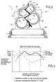
- FIG. 1 is a front view of a fiberizing device according to the invention, seen fiber side.
- This device consists essentially of two identical fibering machines 1, 2 arranged at the entrance of a chamber 3 of reception of the fibers, in which there is a receiving member such as a carpet or an endless belt 4, provided with unrepresented suction boxes, circulating between the two parallel vertical walls 5, 6 of the chamber of reception 3.
- the two machines 1, 2 comprise a series of four wheels of centrifugation 7, 8, 9, 10, in which the first wheel 7 is the smallest, the second wheel 8 is very slightly larger, the third 9 and fourth 10 wheels being the largest and substantially the same diameter.
- the wheels 7, 8, 9, 10 are arranged in an assembly their peripheral surfaces close to each other, spaced apart by the order of 40 mm.
- the line joining the center of the first and second wheels 7, 8 is at an angle of about 25 ° below the horizontal.
- wheels 7, 8, 9, 10 are rotated by means of engine blocks 11, 12, the two right wheels 7, 9 are driven for example in the direction trigonometrically, while the two left-hand wheels 8, 10 are driven by opposite direction, so that two consecutive wheels on the path of the material to fiber (which goes down from the highest wheel 7 to the lowest 10) turn into reverse.
- the four wheels 7, 8, 9, 10 are mounted on four shafts substantially parallel to each other, respectively defining the axes 13, 14 of each machine shown in Figure 2.
- the trees are contained in a caisson 15 of profiled shape to marry closer to the outline of internal elements.
- the engine blocks 11, 12 are advantageously arranged aside in a configuration allowing the air to circulate freely around the caisson 15.
- the two machines 1, 2 are further separated by an empty space allowing the passage of air between the two machines. Similarly, the space located on each side of the machines 1, 2 is left free to allow the passage induced air between the machines 1, 2 and the walls 5, 6 of the chamber 3 of reception.
- Each machine 1, 2 is mounted on a chassis 16 resting on the ground on feet or wheels rolling in rails, which move the machines for their maintenance.
- the rails are fixed to the ground so that the main axis 13 of the machine 1 makes an angle of about 8 ° with the direction of the walls 5, 6, which is also the axis of the reception line (direction of advancement of the band 4 indicated by the arrow F), while the main axis 14 of the machine 2 makes a angle of about 4 ° with the direction of the walls 5, 6.
- the two machines 1, 2 could be mounted on swiveling turrets, which can be moved, if necessary, for machine maintenance.
- Each machine 1, 2 is further equipped with air blowing means of stretching constituted by rings 17, 18, 19, 20 concentric with the wheels 7, 8, 9, 10 and provided with orifices 21, 22, 23, 24 forming lips stretching.
- the rings 17, 18, 19, 20 are disposed of way that their external surface is coplanar with the rear face of the wheels 7, 8, 9, 10. The absence of any protruding part on the sides of the wheels avoids the anchoring of fibers on the facade of the machine, the accumulation of which wheels is detrimental to the proper functioning of the machine.
- the orifices 21, 22, 23, 24 run along the peripheral surface respectively wheels 7, 8, 9, 10 over a length such that they allow the passage of a continuous gas stream following substantially all the outer casing of the peripheral surfaces of the wheels 7, 8, 9, 10.
- the blowing air is conveyed to the drawing lips by means of a fan 25 advantageously arranged in the lower part of the box 15: the air aspirated from the ambient atmosphere is injected inside the casing 15, where it circulates around the trees driving the wheels, before going out through orifices 21, 22, 23, 24.
- the air sees its speed becoming homogenized by so that the speed of the air ejected by an orifice varies only by at most 10% along this last.
- the ejection speed at the lip outlet varies according to the location of the crown according to the space available for air in the box 1 5 around the trees: it is maximum for the lower crown 20 and minimum for the crown 17 which is the highest.
- Each machine 1, 2 can also be equipped with means 26 of cooling the surface located between the wheels 7, 8, 9, 10, in particular by water circulation (water-jacket type). Due to the relatively spacing large between the wheels, this water jacket can be formed in one piece, ensuring cooling of the entire surface.
- water circulation water-jacket type
- the rings 17, 18, 19, 20 are arranged so as to flush with the surface of the front of the machine 1, 2 which carries the wheels 7, 8, 9, 10, this facade may possibly be constituted by the water jacket 26.
- each wheel is stretched axially by stretching air exiting the lips 21, 22, 23, 24 which air partially ensures the transport of the fibers to the reception mat 4 in the room 3 where reigns also a suction of air in the same axial direction.
- the fibers received from the machines 1 and 2 are collected in the form of a sheet of variable thickness depending on the flow of material fondue feeding the machines 1, 2 and the speed of advance of the carpet 4.
- the machines 1, 2 also comprise means for supplying a binder, not shown, known per se, which bind the fibers together in the tablecloth.
- the formation of fibers according to the invention advantageously takes place mainly in the central part of the machines 1, 2 thanks to a suitable path of the molten material 30 which performs a double rebound on the third wheel 9. This path is also advantageous for ensuring a high fiber drawing efficiency.
- This path can be obtained by turning the second wheel 8 to a velocity high enough for the jet of molten material to hit the third wheel at a point (or area) of impact relatively close to the top of the third wheel.
- Favorable fiberization conditions include the rotational drive of the second wheel of each series to a speed greater than or equal to 6500 rpm for a wheel diameter less than or equal to 240 mm.
- Cooling of the surface between the wheels 7, 8, 9, 10 allows to avoid the accumulation of hot melt by adhesion to the facade: contrary the melt 30 possibly ejected on the facade, frozen in cooling and falls under the effect of its own weight.
- the machines 1, 2 form fibers that have sufficient space around the wheels 7, 8, 9, 10 to bloom coaxially fiber-like torus with the wheel in direction of the reception room 3.
- the drawing lips 21, 22, 23, 24 are hollowed out obliquely in the crowns 17, 18, 19, 20 so as to unclog at an angle of the order of 10 to 16 ° with respect to the axis of rotation of the wheels, the art of drawing can also participate in the development of a large torus.
- the air blowing obliquely avoids over cooling the wheels and allows to maintain the conditions of ejection of the fibers.
- the convergent orientation of machines 1, 2 in relation to the direction walls 5, 6 of the receiving chamber 3, can counter the effect of wall through which the jet of fibers emitted by a machine is sucked towards the wall neighbor under the action of the depression created by gaseous streams from the blowing means along the walls.
- the drafts blowing and induced emitted by the two adjacent machines converge, that is to say that they meet and add to the frontal area between machines 1, 2 and deviate substantially from the walls 5, 6 to give improved stretching and fiber transport conditions.
- the layer of fibers collected on the carpet 4 has good cohesion, with a uniform basis weight (no holes or holes in the sheet).
- This speed profile is representative of the speed profile of the elements projected by centrifugal ejection from fiber-drawing machines: indeed, the same profile was obtained by measuring oil droplet velocities present in the same gas flow produced by a model aeraulic scale 1/8 compared to an industrial line, the measurements of speeds being in this case carried out by a so-called optical laser method Laser Doppler anemometry. These measurements were carried out at UMR 6614 of CORIA. These measurements give detailed cartographies in two dimensions (2D) velocity at any point of reception, from which one can draw a graph such as that of Figure 4.
- 2D two dimensions
- This graph shows that when machines are arranged with their respective main axes strictly parallel to the line axis of reception and direction of the walls of the chamber, the speed profile has a maximum of about a quarter (1 ⁇ 4) of the width of the carpet, a at least two-thirds (2/3) of the carpet width, the speed increasing again on the last third.
- This speed profile illustrates the effect of wall stated above.
- the speed variation between the maximum and the minimum is more than 30%.
- the invention has just been described more particularly in the case of a reception room with parallel walls. It also applies to installations having a different configuration, the orientation of the machines of fiberizing is then modified according to the new conditions to obtain the profile desired speed.
- a study on a somehowlic model as described above advantageously makes it possible to determine the appropriate disposition.
Landscapes
- Chemical & Material Sciences (AREA)
- Engineering & Computer Science (AREA)
- Materials Engineering (AREA)
- Geochemistry & Mineralogy (AREA)
- Manufacturing & Machinery (AREA)
- General Life Sciences & Earth Sciences (AREA)
- Life Sciences & Earth Sciences (AREA)
- Organic Chemistry (AREA)
- Spinning Methods And Devices For Manufacturing Artificial Fibers (AREA)
- Manufacture, Treatment Of Glass Fibers (AREA)
- Nonwoven Fabrics (AREA)
- Inorganic Fibers (AREA)
- Chemical Or Physical Treatment Of Fibers (AREA)
Claims (17)
- Verfahren zur Herstellung von Mineralfasern, bei dem zu zerfaserndes Material (30) mindestens zwei seitlich nebeneinander angeordneten Zerfaserungsmaschinen (1, 2) gleichzeitig zugeführt wird, wobei jede Maschine (1, 2) eine Serie von Schleuderrädern (7, 8, 9, 10) aufweist, die kaskadenförmig angeordnet sind und um Achsen, die alle im wesentlichen die gleiche Richtung haben und als Hauptachse (13, 14) bezeichnet werden, drehend angetrieben werden, wobei zwei aufeinanderfolgende Räder der Kaskade gegensinnig drehen, das zu zerfasernde Material im geschmolzenen Zustand in jeder Maschine auf die Umfangsfläche des ersten Rades (7) gegossen wird, durch welches es beschleunigt und auf das zweite Rad (8), und gegebenenfalls nacheinander auf die anderen Rädern (9, 10) der Serie weitergegeben wird, so daß es unter der Einwirkung der Fliehkraft in Fasern umgeformt wird,
und wobei die von den verschiedenen Rädern einer Maschine gebildeten Fasern von einem Gasstrom erfaßt werden, der von jeder Maschine in einer zu der Hauptachse im wesentlichen parallelen Richtung abgegeben wird, und von einem Ablageorgan (4) aufgefangen werden,
dadurch gekennzeichnet, daß die Hauptachsen (13, 14) von zwei benachbarten Maschinen (1, 2) gemäß einem von Null verschiedenen Winkel angeordnet werden, wobei dieser Winkel bzw. jeder Winkel zwischen zwei benachbarten Maschinen so angepaßt wird, daß zwei von den zwei benachbarten Maschinen (1, 2) abgegebene Gasströme sich treffen und verbinden. - Verfahren zur Herstellung von Mineralfasern nach Anspruch 1, dadurch gekennzeichnet, daß der Winkel bzw. jeder Winkel zwischen zwei benachbarten Maschinen so angepaßt wird, daß die axiale Komponente der Geschwindigkeit des gesamten Gasstroms auf Höhe des Ablageorgans (4) über mindestens 50% der Breite des Ablageorgans (4) um höchstens 20% variiert.
- Verfahren zur Herstellung von Mineralfasern nach Anspruch 1 oder 2, dadurch gekennzeichnet, daß der Winkel bzw. jeder Winkel zwischen zwei benachbarten Maschinen so angepaßt wird, daß die axiale Komponente der Geschwindigkeit des Gasstroms auf Höhe des Ablageorgans (4) über die Breite des Ablageorgans auf im wesentlichen symmetrische Weise variiert.
- Verfahren zur Herstellung von Mineralfasern nach einem der Ansprüche 1 bis 3, dadurch gekennzeichnet, daß jede Maschine (1, 2) eine Serie von vier Schleuderrädern (7, 8, 9, 10) aufweist, sowie dadurch, daß die Anordnung und die Drehgeschwindigkeit der Schleuderräder so angepaßt wird, daß ein Teil des zu zerfasemden Materials, welches das vierte Rad (10) erreicht, auf das dritte (9) weitergegeben und dort in Fasern umgeformt wird.
- Verfahren nach Anspruch 4, dadurch gekennzeichnet, daß das zweite Rad (8) einer jeden Serie bei einem Durchmesser von weniger als oder gleich 240 mm mit einer Geschwindigkeit von mehr als oder gleich 6500 U/min drehend angetrieben wird.
- Vorrichtung zur Herstellung von Mineralfasern nach einem der vorhergehenden Ansprüche, mit mindestens zwei seitlich nebeneinander angeordneten Zerfaserungsmaschinen (1, 2) am Eintritt in eine Kammer (3), wobei jede Maschine (1, 2) eine Serie von Schleuderrädem (7, 8, 9, 10) aufweist, die kaskadenförmig angeordnet sind und um Achsen, die alle im wesentlichen die gleiche Richtung haben und als Hauptachse (13, 14) bezeichnet werden, drehend angetrieben werden, wobei zwei aufeinanderfolgende Räderder Kaskade gegensinnig drehen, und Gebläseeinrichtungen (17, 18, 19, 20) aufweist, die um die Serie von Schleuderrädem einen Gasstrom in einer zu der Hauptachse im wesentlichen parallelen Richtung erzeugen, wobei die Vorrichtung Zuführeinrichtungen aufweist, die derart angeordnet sind, daß sie ein zu zerfaserndes Material (30) im geschmolzenen Zustand gleichzeitig auf die Umfangsfläche des ersten Rades (7) einer jeden Maschine (1, 2) gießen,
und ferner mit einem Ablageorgan (4), das den Zerfaserungsmaschinen (1, 2) gegenüberliegend in der Kammer (3) angeordnet ist, dadurch gekennzeichnet, daß die Hauptachsen (13, 14) von zwei benachbarten Maschinen (1, 2) gemäß einem von Null verschiedenen Winkel angeordnet sind, wobei dieser Winkel bzw. jeder Winkel zwischen zwei benachbarten Maschinen so angepaßt ist, daß zwei von den zwei benachbarten Maschinen (1, 2) abgegebene Gasströme sich treffen und verbinden. - Vorrichtung nach Anspruch 6, dadurch gekennzeichnet, daß die Kammer (3) zwei vertikale Wände (5, 6) aufweist, die sich auf zwei Seiten des Ablageorgans (4) im wesentlichen parallel von den am Eintritt angeordneten Maschinen (1, 2) erstrecken, wobei eine zu der ersten Wand (5) benachbarte erste Maschine (1) und eine zu der zweiten Wand (6) benachbarte zweite Maschine (2) so angeordnet sind, daß ihre jeweiligen Hauptachsen (13, 14) auf die Mitter der Kammer (3) hin konvergieren, bevorzugt in einem Winkel von mindestens 2° in Bezug auf die Richtung der Wände (5, 6).
- Vorrichtung nach Anspruch 7, dadurch gekennzeichnet, daß die erste Maschine (1) so ausgelegt ist, daß ihr erstes Schleuderrad (7) das Schmelzematerial (30) gegen die erste Wand (5) abgibt, und die zweite Maschine (2) so ausgelegt ist, daß ihr erstes Schleuderrad (7) das Schmelzematerial (30) auf die zweite Wand (6) hin abgibt, sowie dadurch, daß die Achse (14) der zweiten Maschine (2) mit der zweiten Wand (6) einen Winkel bildet, der größer als derjenige ist, der von der Achse (13) der ersten Maschine (1) mit der ersten Wand (5) gebildet wird.
- Vorrichtung nach Anspruch 8, dadurch gekennzeichnet, daß der erste Winkel in der Größenordnung von 2 bis 6°, bevorzugt in der Größenordnung von 4° ist, und der zweite Winkel in der Größenordnung von 2 bis 10°, bevorzugt in der Größenordnung von 4 bis 8° ist.
- Vorrichtung nach Anspruch 6, dadurch gekennzeichnet, daß die Kammer (3) zwei vertikale Wände (5, 6) aufweist, die sich auf zwei Seiten des Ablageorgans (4) erstrecken und von den am Eintritt angeordneten Maschinen (1, 2) auf das Ablageorgan (4) hin konvergieren, wobei eine zu der ersten Wand (5) benachbarte erste Maschine (1) und eine zu der zweiten Wand (6) benachbarte zweite Maschine (2) so angeordnet sind, daß ihre jeweiligen Hauptachsen (13, 14) auf die jeweilige benachbarte Wand (5, 6) hin divergieren.
- Vorrichtung nach einem der Ansprüche 6 bis 10, dadurch gekennzeichnet, daß in jeder Maschine (1, 2) das zweite Schleuderrad (8) einen Durchmesser von weniger als oder gleich 240 mm aufweist.
- Vorrichtung nach Anspruch 11, dadurch gekennzeichnet, daß eine Verbindungslinie zwischen den Mittelpunkten der zwei ersten Schleuderräder (7, 8) einen Winkel von mehr als 20°, bevorzugt in der Größenordnung von 25°, zur Horizontalen bildet.
- Vorrichtung nach einem der Ansprüche 6 bis 12, dadurch gekennzeichnet, daß der Umfang eines Rades vom Umfang eines benachbarten Rades um eine Strecke von mindestens 40 mm beabstandet ist.
- Vorrichtung nach einem der Ansprüche 6 bis 13, dadurch gekennzeichnet, daß die Gebläseeinrichtungen (17, 18, 19, 20) mindestens eine Ausziehlippe (21, 22, 23, 24) aufweisen, die derart ausgelegt ist/sind, daß ein kontinuierlicher Luftstrom produziert wird, der im wesentlichen den gesamten Außenmantel der Umfangsflächen der Schleuderräder (7, 8, 9, 10) bestreicht.
- Vorrichtung nach einem der Ansprüche 6 bis 14, dadurch gekennzeichnet, daß die Gebläseeinrichtungen (17, 18, 19, 20) so ausgelegt sind, daß sie entlang eines unteren Abschnitts mindestens eines Rades der Kaskade einen breiteren Gasstrom erzeugen.
- Vorrichtung nach einem der Ansprüche 6 bis 15, dadurch gekennzeichnet, daß die Gebläseeinrichtungen (17, 18, 19, 20) in der Nähe eines Schleuderrades ausmünden und dabei in einem Winkel in der Größenordnung von 10 bis 16° in Bezug auf die Drehachse des Rades abweichen.
- Vorrichtung nach einem der Ansprüche 6 bis 16, dadurch gekennzeichnet, daß sie zwischen zwei benachbarten Zerfaserungsmaschinen (1, 2) einen offenen Raum aufweist, der das Zirkulieren von Luft zwischen den Maschinen (1, 2) ermöglicht.
Priority Applications (1)
| Application Number | Priority Date | Filing Date | Title |
|---|---|---|---|
| DE69924442T DE69924442T3 (de) | 1998-04-24 | 1999-04-22 | Vorrichtung zum zerfasern von mineralwolle durch freies zentrifugieren |
Applications Claiming Priority (3)
| Application Number | Priority Date | Filing Date | Title |
|---|---|---|---|
| FR9805198A FR2777881A1 (fr) | 1998-04-24 | 1998-04-24 | Procede et dispositif de fibrage de laine minerale par centrifugation libre |
| FR9805198 | 1998-04-24 | ||
| PCT/FR1999/000954 WO1999055631A1 (fr) | 1998-04-24 | 1999-04-22 | Procede et dispositif de fibrage de laine minerale par centrifugation libre |
Publications (3)
| Publication Number | Publication Date |
|---|---|
| EP0991601A1 EP0991601A1 (de) | 2000-04-12 |
| EP0991601B1 true EP0991601B1 (de) | 2005-03-30 |
| EP0991601B2 EP0991601B2 (de) | 2013-01-16 |
Family
ID=9525666
Family Applications (1)
| Application Number | Title | Priority Date | Filing Date |
|---|---|---|---|
| EP99915810A Expired - Lifetime EP0991601B2 (de) | 1998-04-24 | 1999-04-22 | Vorrichtung zum zerfasern von mineralwolle durch freies zentrifugieren |
Country Status (23)
| Country | Link |
|---|---|
| US (1) | US6536241B1 (de) |
| EP (1) | EP0991601B2 (de) |
| JP (1) | JP2002506417A (de) |
| CN (1) | CN1266413A (de) |
| AR (1) | AR019085A1 (de) |
| AT (1) | ATE292096T1 (de) |
| AU (1) | AU3425699A (de) |
| BR (1) | BR9906380A (de) |
| CA (1) | CA2294440C (de) |
| CZ (1) | CZ298321B6 (de) |
| DE (1) | DE69924442T3 (de) |
| DK (1) | DK0991601T4 (de) |
| ES (1) | ES2241276T5 (de) |
| FR (1) | FR2777881A1 (de) |
| HR (1) | HRP990403A2 (de) |
| HU (1) | HUP0002366A3 (de) |
| IS (1) | IS5279A (de) |
| NO (1) | NO996124L (de) |
| PL (1) | PL190266B1 (de) |
| PT (1) | PT991601E (de) |
| SK (1) | SK181399A3 (de) |
| WO (1) | WO1999055631A1 (de) |
| ZA (1) | ZA997514B (de) |
Families Citing this family (7)
| Publication number | Priority date | Publication date | Assignee | Title |
|---|---|---|---|---|
| DE60106088T2 (de) * | 2000-10-18 | 2005-02-03 | Rockwool International A/S | Vorrichtung zur herstellung von glasartigen fasern durch zentrifugenspinnen |
| FR2835906B1 (fr) | 2002-02-13 | 2004-06-04 | Saint Gobain Isover | Bruleur a combustion interne, notamment pour l'etirage de fibres minerales |
| CN102211861A (zh) * | 2011-05-06 | 2011-10-12 | 德清县延炜耐火材料厂 | 离心式超长丝矿渣棉的生产方法 |
| CN102585121B (zh) * | 2011-12-22 | 2014-04-02 | 中科院广州化学有限公司 | 一种可用作白板笔墨水分散剂的嵌段聚合物和白板笔墨水 |
| CN103265168B (zh) * | 2013-05-20 | 2015-08-05 | 中材科技股份有限公司 | 一种用于岩棉成纤系统的四辊离心机 |
| CN104370458A (zh) * | 2013-08-12 | 2015-02-25 | 苏州宏久航空防热材料科技有限公司 | 一种用于支撑离心机的结构 |
| CN119977315B (zh) * | 2025-02-17 | 2025-09-23 | 河北鼎泰蓝星化工建材有限公司 | 一种岩棉离心甩丝机及方法 |
Family Cites Families (14)
| Publication number | Priority date | Publication date | Assignee | Title |
|---|---|---|---|---|
| NL264233A (de) † | 1960-05-05 | |||
| US3709670A (en) * | 1970-09-10 | 1973-01-09 | H Eriksen | Method, apparatus and system for fiberizing molten mineral material |
| SE403099C (sv) * | 1976-06-30 | 1984-04-09 | Rockwool Ab | Anordning for fibrering av en mineralsmelta |
| NZ234718A (en) | 1989-08-11 | 1992-05-26 | Saint Gobain Isover | Decomposable glass fibres |
| FR2657077B1 (fr) | 1990-01-16 | 1993-07-02 | Saint Gobain Isover | Procede et dispositif de fibrage de laine minerale par centrifugation libre. |
| YU159091A (sh) * | 1990-09-28 | 1995-12-04 | Rockwool International A/S | Postupak i uredjaj za proizvodnju vlakana za mineralnu vunu |
| GB9100884D0 (en) † | 1991-01-16 | 1991-02-27 | Rockwool Int | Stone wool |
| GB9100887D0 (en) * | 1991-01-16 | 1991-02-27 | Rockwool Int | Process and apparatus for making mineral wool fibres |
| GB9100886D0 (en) * | 1991-01-16 | 1991-02-27 | Rockwool Int | Process and apparatus for making mineral wool fibres |
| FR2690438A1 (fr) | 1992-04-23 | 1993-10-29 | Saint Gobain Isover | Fibres minérales susceptibles de se dissoudre en milieu physiologique. |
| DE4402802C2 (de) | 1994-01-31 | 2003-01-30 | Hilti Ag | Werkzeug und Werkzeugaufnahme für Handwerkzeuggeräte |
| GB9509813D0 (en) * | 1995-05-15 | 1995-07-05 | Rockwool Int | Method and apparatus for the manufacture of man-made vitreous fibre products |
| GB9509782D0 (en) * | 1995-05-15 | 1995-07-05 | Rockwool Int | Man-made vitreous fibre products and processes and apparatus for their production |
| PL191294B1 (pl) † | 1998-04-06 | 2006-04-28 | Rockwool Int | Sposób wytwarzania płata ze sztucznych włókien szklistych, urządzenie do wytwarzania płata ze sztucznych włókien szklistych, płat ze sztucznych włókien szklistych i urządzenie do wytwarzania wstęgi ze sztucznych włókien szklistych |
-
1998
- 1998-04-24 FR FR9805198A patent/FR2777881A1/fr active Pending
-
1999
- 1999-04-21 AR ARP990101830A patent/AR019085A1/es unknown
- 1999-04-22 BR BR9906380-8A patent/BR9906380A/pt not_active Application Discontinuation
- 1999-04-22 US US09/446,111 patent/US6536241B1/en not_active Expired - Lifetime
- 1999-04-22 DE DE69924442T patent/DE69924442T3/de not_active Expired - Lifetime
- 1999-04-22 PL PL99337366A patent/PL190266B1/pl unknown
- 1999-04-22 CN CN99800615A patent/CN1266413A/zh active Pending
- 1999-04-22 PT PT99915810T patent/PT991601E/pt unknown
- 1999-04-22 CA CA002294440A patent/CA2294440C/fr not_active Expired - Fee Related
- 1999-04-22 ES ES99915810T patent/ES2241276T5/es not_active Expired - Lifetime
- 1999-04-22 DK DK99915810.8T patent/DK0991601T4/da active
- 1999-04-22 AT AT99915810T patent/ATE292096T1/de active
- 1999-04-22 EP EP99915810A patent/EP0991601B2/de not_active Expired - Lifetime
- 1999-04-22 HU HU0002366A patent/HUP0002366A3/hu unknown
- 1999-04-22 SK SK1813-99A patent/SK181399A3/sk unknown
- 1999-04-22 AU AU34256/99A patent/AU3425699A/en not_active Abandoned
- 1999-04-22 WO PCT/FR1999/000954 patent/WO1999055631A1/fr not_active Ceased
- 1999-04-22 HR HR98/05198A patent/HRP990403A2/hr not_active Application Discontinuation
- 1999-04-22 JP JP55372399A patent/JP2002506417A/ja active Pending
- 1999-04-22 CZ CZ0470299A patent/CZ298321B6/cs not_active IP Right Cessation
- 1999-11-30 IS IS5279A patent/IS5279A/is unknown
- 1999-12-07 ZA ZA9907514A patent/ZA997514B/xx unknown
- 1999-12-10 NO NO996124A patent/NO996124L/no not_active Application Discontinuation
Also Published As
| Publication number | Publication date |
|---|---|
| CA2294440A1 (fr) | 1999-11-04 |
| HRP990403A2 (en) | 2000-04-30 |
| ES2241276T3 (es) | 2005-10-16 |
| ATE292096T1 (de) | 2005-04-15 |
| HUP0002366A2 (hu) | 2000-11-28 |
| WO1999055631A1 (fr) | 1999-11-04 |
| PL190266B1 (pl) | 2005-11-30 |
| SK181399A3 (en) | 2000-06-12 |
| DK0991601T4 (da) | 2013-04-29 |
| BR9906380A (pt) | 2000-07-11 |
| CA2294440C (fr) | 2008-06-10 |
| EP0991601A1 (de) | 2000-04-12 |
| HUP0002366A3 (en) | 2001-07-30 |
| NO996124D0 (no) | 1999-12-10 |
| DE69924442T2 (de) | 2006-02-16 |
| NO996124L (no) | 1999-12-10 |
| FR2777881A1 (fr) | 1999-10-29 |
| PL337366A1 (en) | 2000-08-14 |
| AR019085A1 (es) | 2001-12-26 |
| ES2241276T5 (es) | 2013-05-06 |
| PT991601E (pt) | 2005-08-31 |
| US6536241B1 (en) | 2003-03-25 |
| DE69924442T3 (de) | 2013-05-29 |
| DE69924442D1 (de) | 2005-05-04 |
| IS5279A (is) | 1999-11-30 |
| ZA997514B (en) | 2000-06-08 |
| JP2002506417A (ja) | 2002-02-26 |
| CZ298321B6 (cs) | 2007-08-29 |
| AU3425699A (en) | 1999-11-16 |
| EP0991601B2 (de) | 2013-01-16 |
| CN1266413A (zh) | 2000-09-13 |
| CZ470299A3 (cs) | 2000-07-12 |
| DK0991601T3 (da) | 2005-08-01 |
Similar Documents
| Publication | Publication Date | Title |
|---|---|---|
| EP0439385B1 (de) | Verfahren und Vorrichtung zum Ziehen von Mineralwollfasern durch freies Zentrifugieren | |
| CA2436894C (fr) | Procede et dispositif de formation de laine minerale | |
| EP0519797B1 (de) | Verfahren und Vorrichtung zum Herstellen von Fasern | |
| EP0406107B1 (de) | Verfahren und Einrichtung zur Ablagerung von Mineralfasern | |
| FR2559793A1 (fr) | Procede de production de matelas de fibres minerales a partir d'un materiau fondu | |
| EP0072300A1 (de) | Verfahren und Vorrichtung zur Verteilung von durch einen Gasstrom transportierten Fasern auf einem Aufnahmeteil | |
| EP0091866B1 (de) | Herstellung von Fasern durch Zentrifugieren | |
| EP0091381B1 (de) | Herstellen von Fasern durch Zentrifugieren und Blasen | |
| CA2294440C (fr) | Procede et dispositif de fibrage de laine minerale par centrifugation libre | |
| FR2993265A1 (fr) | Dispositif de formation de fibres minerales | |
| EP0059145B1 (de) | Verfahren und Vorrichtung zur Herstellung von Fasern, ausgehend von ziehbarem Material | |
| FR2736940A1 (fr) | Procede et dispositif pour la formation d'un feutre de fibres minerales de qualite amelioree | |
| EP0801635B1 (de) | Verfahren und vorrichtung für freie zentrifugation von mineralfasern | |
| EP0406106B1 (de) | Verfahren und Einrichtung zur Ablagerung von Mineralfasern | |
| EP0119124B1 (de) | Faserverteilung in einem Vlies | |
| FR3120372A1 (fr) | Installation de fabrication de laine minerale | |
| WO2018069652A1 (fr) | Procede de formation de fibres minerales | |
| FR2740770A1 (fr) | Procede et dispositif pour la centrifugation libre de fibres minerales | |
| EP0953547A2 (de) | Vorrichtung und Verfahren zum Ziehen von Mineralwollfasern |
Legal Events
| Date | Code | Title | Description |
|---|---|---|---|
| PUAI | Public reference made under article 153(3) epc to a published international application that has entered the european phase |
Free format text: ORIGINAL CODE: 0009012 |
|
| 17P | Request for examination filed |
Effective date: 19991206 |
|
| AK | Designated contracting states |
Kind code of ref document: A1 Designated state(s): AT BE CH DE DK ES FI FR GB GR IE IT LI LU NL PT SE |
|
| AX | Request for extension of the european patent |
Free format text: SI PAYMENT 19991206 |
|
| 17Q | First examination report despatched |
Effective date: 20030207 |
|
| GRAP | Despatch of communication of intention to grant a patent |
Free format text: ORIGINAL CODE: EPIDOSNIGR1 |
|
| GRAS | Grant fee paid |
Free format text: ORIGINAL CODE: EPIDOSNIGR3 |
|
| GRAA | (expected) grant |
Free format text: ORIGINAL CODE: 0009210 |
|
| AK | Designated contracting states |
Kind code of ref document: B1 Designated state(s): AT BE CH DE DK ES FI FR GB GR IE IT LI LU NL PT SE |
|
| AX | Request for extension of the european patent |
Extension state: SI |
|
| RAP1 | Party data changed (applicant data changed or rights of an application transferred) |
Owner name: SAINT-GOBAIN ISOVER |
|
| REG | Reference to a national code |
Ref country code: GB Ref legal event code: FG4D Free format text: NOT ENGLISH |
|
| REG | Reference to a national code |
Ref country code: CH Ref legal event code: EP |
|
| PG25 | Lapsed in a contracting state [announced via postgrant information from national office to epo] |
Ref country code: LU Free format text: LAPSE BECAUSE OF NON-PAYMENT OF DUE FEES Effective date: 20050422 |
|
| REF | Corresponds to: |
Ref document number: 69924442 Country of ref document: DE Date of ref document: 20050504 Kind code of ref document: P |
|
| REG | Reference to a national code |
Ref country code: IE Ref legal event code: FG4D Free format text: LANGUAGE OF EP DOCUMENT: FRENCH |
|
| REG | Reference to a national code |
Ref country code: CH Ref legal event code: NV Representative=s name: KIRKER & CIE SA |
|
| PG25 | Lapsed in a contracting state [announced via postgrant information from national office to epo] |
Ref country code: GR Free format text: LAPSE BECAUSE OF FAILURE TO SUBMIT A TRANSLATION OF THE DESCRIPTION OR TO PAY THE FEE WITHIN THE PRESCRIBED TIME-LIMIT Effective date: 20050630 |
|
| REG | Reference to a national code |
Ref country code: SE Ref legal event code: TRGR |
|
| REG | Reference to a national code |
Ref country code: DK Ref legal event code: T3 |
|
| GBT | Gb: translation of ep patent filed (gb section 77(6)(a)/1977) |
Effective date: 20050713 |
|
| REG | Reference to a national code |
Ref country code: PT Ref legal event code: SC4A Effective date: 20050624 |
|
| REG | Reference to a national code |
Ref country code: ES Ref legal event code: FG2A Ref document number: 2241276 Country of ref document: ES Kind code of ref document: T3 |
|
| PLBI | Opposition filed |
Free format text: ORIGINAL CODE: 0009260 |
|
| PLAX | Notice of opposition and request to file observation + time limit sent |
Free format text: ORIGINAL CODE: EPIDOSNOBS2 |
|
| 26 | Opposition filed |
Opponent name: ROCKWOOL INTERNATIONAL A/S Effective date: 20051230 |
|
| NLR1 | Nl: opposition has been filed with the epo |
Opponent name: ROCKWOOL INTERNATIONAL A/S |
|
| PLAF | Information modified related to communication of a notice of opposition and request to file observations + time limit |
Free format text: ORIGINAL CODE: EPIDOSCOBS2 |
|
| PLAF | Information modified related to communication of a notice of opposition and request to file observations + time limit |
Free format text: ORIGINAL CODE: EPIDOSCOBS2 |
|
| PLBB | Reply of patent proprietor to notice(s) of opposition received |
Free format text: ORIGINAL CODE: EPIDOSNOBS3 |
|
| PLAB | Opposition data, opponent's data or that of the opponent's representative modified |
Free format text: ORIGINAL CODE: 0009299OPPO |
|
| PLAB | Opposition data, opponent's data or that of the opponent's representative modified |
Free format text: ORIGINAL CODE: 0009299OPPO |
|
| R26 | Opposition filed (corrected) |
Opponent name: ROCKWOOL INTERNATIONAL A/S Effective date: 20051230 |
|
| APAH | Appeal reference modified |
Free format text: ORIGINAL CODE: EPIDOSCREFNO |
|
| APBM | Appeal reference recorded |
Free format text: ORIGINAL CODE: EPIDOSNREFNO |
|
| APBP | Date of receipt of notice of appeal recorded |
Free format text: ORIGINAL CODE: EPIDOSNNOA2O |
|
| APBU | Appeal procedure closed |
Free format text: ORIGINAL CODE: EPIDOSNNOA9O |
|
| PUAH | Patent maintained in amended form |
Free format text: ORIGINAL CODE: 0009272 |
|
| STAA | Information on the status of an ep patent application or granted ep patent |
Free format text: STATUS: PATENT MAINTAINED AS AMENDED |
|
| 27A | Patent maintained in amended form |
Effective date: 20130116 |
|
| AK | Designated contracting states |
Kind code of ref document: B2 Designated state(s): AT BE CH DE DK ES FI FR GB GR IE IT LI LU NL PT SE |
|
| AX | Request for extension of the european patent |
Extension state: SI |
|
| REG | Reference to a national code |
Ref country code: DE Ref legal event code: R102 Ref document number: 69924442 Country of ref document: DE |
|
| REG | Reference to a national code |
Ref country code: CH Ref legal event code: AELC |
|
| REG | Reference to a national code |
Ref country code: CH Ref legal event code: AELC |
|
| REG | Reference to a national code |
Ref country code: DE Ref legal event code: R102 Ref document number: 69924442 Country of ref document: DE Effective date: 20130116 |
|
| REG | Reference to a national code |
Ref country code: DK Ref legal event code: T4 |
|
| REG | Reference to a national code |
Ref country code: SE Ref legal event code: RPEO |
|
| REG | Reference to a national code |
Ref country code: ES Ref legal event code: DC2A Ref document number: 2241276 Country of ref document: ES Kind code of ref document: T5 Effective date: 20130506 |
|
| REG | Reference to a national code |
Ref country code: NL Ref legal event code: T3 |
|
| PGFP | Annual fee paid to national office [announced via postgrant information from national office to epo] |
Ref country code: IE Payment date: 20140410 Year of fee payment: 16 |
|
| PGFP | Annual fee paid to national office [announced via postgrant information from national office to epo] |
Ref country code: CH Payment date: 20140414 Year of fee payment: 16 Ref country code: AT Payment date: 20140326 Year of fee payment: 16 Ref country code: PT Payment date: 20140404 Year of fee payment: 16 Ref country code: IT Payment date: 20140418 Year of fee payment: 16 Ref country code: FI Payment date: 20140410 Year of fee payment: 16 |
|
| PGFP | Annual fee paid to national office [announced via postgrant information from national office to epo] |
Ref country code: BE Payment date: 20140429 Year of fee payment: 16 |
|
| REG | Reference to a national code |
Ref country code: PT Ref legal event code: MM4A Free format text: LAPSE DUE TO NON-PAYMENT OF FEES Effective date: 20151022 |
|
| REG | Reference to a national code |
Ref country code: CH Ref legal event code: PL |
|
| REG | Reference to a national code |
Ref country code: AT Ref legal event code: MM01 Ref document number: 292096 Country of ref document: AT Kind code of ref document: T Effective date: 20150422 |
|
| REG | Reference to a national code |
Ref country code: IE Ref legal event code: MM4A |
|
| PG25 | Lapsed in a contracting state [announced via postgrant information from national office to epo] |
Ref country code: IT Free format text: LAPSE BECAUSE OF NON-PAYMENT OF DUE FEES Effective date: 20150422 Ref country code: FI Free format text: LAPSE BECAUSE OF NON-PAYMENT OF DUE FEES Effective date: 20150422 Ref country code: CH Free format text: LAPSE BECAUSE OF NON-PAYMENT OF DUE FEES Effective date: 20150430 Ref country code: LI Free format text: LAPSE BECAUSE OF NON-PAYMENT OF DUE FEES Effective date: 20150430 |
|
| PG25 | Lapsed in a contracting state [announced via postgrant information from national office to epo] |
Ref country code: AT Free format text: LAPSE BECAUSE OF NON-PAYMENT OF DUE FEES Effective date: 20150422 Ref country code: PT Free format text: LAPSE BECAUSE OF NON-PAYMENT OF DUE FEES Effective date: 20151022 |
|
| REG | Reference to a national code |
Ref country code: FR Ref legal event code: PLFP Year of fee payment: 18 |
|
| PG25 | Lapsed in a contracting state [announced via postgrant information from national office to epo] |
Ref country code: IE Free format text: LAPSE BECAUSE OF NON-PAYMENT OF DUE FEES Effective date: 20150422 |
|
| REG | Reference to a national code |
Ref country code: FR Ref legal event code: PLFP Year of fee payment: 19 |
|
| PGFP | Annual fee paid to national office [announced via postgrant information from national office to epo] |
Ref country code: ES Payment date: 20170317 Year of fee payment: 19 Ref country code: NL Payment date: 20170412 Year of fee payment: 19 |
|
| PG25 | Lapsed in a contracting state [announced via postgrant information from national office to epo] |
Ref country code: BE Free format text: LAPSE BECAUSE OF NON-PAYMENT OF DUE FEES Effective date: 20150430 |
|
| PGFP | Annual fee paid to national office [announced via postgrant information from national office to epo] |
Ref country code: DE Payment date: 20170420 Year of fee payment: 19 Ref country code: GB Payment date: 20170419 Year of fee payment: 19 Ref country code: DK Payment date: 20170411 Year of fee payment: 19 |
|
| PGFP | Annual fee paid to national office [announced via postgrant information from national office to epo] |
Ref country code: SE Payment date: 20170411 Year of fee payment: 19 |
|
| REG | Reference to a national code |
Ref country code: FR Ref legal event code: PLFP Year of fee payment: 20 |
|
| PGFP | Annual fee paid to national office [announced via postgrant information from national office to epo] |
Ref country code: FR Payment date: 20180425 Year of fee payment: 20 |
|
| REG | Reference to a national code |
Ref country code: DE Ref legal event code: R119 Ref document number: 69924442 Country of ref document: DE |
|
| REG | Reference to a national code |
Ref country code: DK Ref legal event code: EBP Effective date: 20180430 |
|
| REG | Reference to a national code |
Ref country code: SE Ref legal event code: EUG |
|
| REG | Reference to a national code |
Ref country code: NL Ref legal event code: MM Effective date: 20180501 |
|
| GBPC | Gb: european patent ceased through non-payment of renewal fee |
Effective date: 20180422 |
|
| PG25 | Lapsed in a contracting state [announced via postgrant information from national office to epo] |
Ref country code: SE Free format text: LAPSE BECAUSE OF NON-PAYMENT OF DUE FEES Effective date: 20180423 Ref country code: NL Free format text: LAPSE BECAUSE OF NON-PAYMENT OF DUE FEES Effective date: 20180501 Ref country code: DE Free format text: LAPSE BECAUSE OF NON-PAYMENT OF DUE FEES Effective date: 20181101 |
|
| PG25 | Lapsed in a contracting state [announced via postgrant information from national office to epo] |
Ref country code: GB Free format text: LAPSE BECAUSE OF NON-PAYMENT OF DUE FEES Effective date: 20180422 |
|
| PG25 | Lapsed in a contracting state [announced via postgrant information from national office to epo] |
Ref country code: DK Free format text: LAPSE BECAUSE OF NON-PAYMENT OF DUE FEES Effective date: 20180430 |
|
| REG | Reference to a national code |
Ref country code: ES Ref legal event code: FD2A Effective date: 20190912 |
|
| PG25 | Lapsed in a contracting state [announced via postgrant information from national office to epo] |
Ref country code: ES Free format text: LAPSE BECAUSE OF NON-PAYMENT OF DUE FEES Effective date: 20180423 |