EP0991879B1 - Tambour selecteur de vitesses pour une boite de vitesses - Google Patents
Tambour selecteur de vitesses pour une boite de vitesses Download PDFInfo
- Publication number
- EP0991879B1 EP0991879B1 EP98936344A EP98936344A EP0991879B1 EP 0991879 B1 EP0991879 B1 EP 0991879B1 EP 98936344 A EP98936344 A EP 98936344A EP 98936344 A EP98936344 A EP 98936344A EP 0991879 B1 EP0991879 B1 EP 0991879B1
- Authority
- EP
- European Patent Office
- Prior art keywords
- gear
- shifting drum
- shift
- shifting
- curved track
- Prior art date
- Legal status (The legal status is an assumption and is not a legal conclusion. Google has not performed a legal analysis and makes no representation as to the accuracy of the status listed.)
- Expired - Lifetime
Links
- 230000005540 biological transmission Effects 0.000 claims description 9
- 229910000831 Steel Inorganic materials 0.000 claims description 7
- 239000010959 steel Substances 0.000 claims description 7
- 238000010276 construction Methods 0.000 claims description 5
- 239000000463 material Substances 0.000 claims description 4
- 239000010437 gem Substances 0.000 claims 1
- 238000009434 installation Methods 0.000 claims 1
- 238000004519 manufacturing process Methods 0.000 description 8
- 230000033001 locomotion Effects 0.000 description 6
- 238000013459 approach Methods 0.000 description 5
- 238000011161 development Methods 0.000 description 4
- 230000002441 reversible effect Effects 0.000 description 4
- 238000005520 cutting process Methods 0.000 description 3
- 238000013461 design Methods 0.000 description 2
- 238000004049 embossing Methods 0.000 description 2
- 239000002184 metal Substances 0.000 description 2
- 238000005457 optimization Methods 0.000 description 2
- 238000012545 processing Methods 0.000 description 2
- 239000000243 solution Substances 0.000 description 2
- 230000001960 triggered effect Effects 0.000 description 2
- 238000004026 adhesive bonding Methods 0.000 description 1
- 230000001419 dependent effect Effects 0.000 description 1
- 230000026058 directional locomotion Effects 0.000 description 1
- 238000006073 displacement reaction Methods 0.000 description 1
- 238000002347 injection Methods 0.000 description 1
- 239000007924 injection Substances 0.000 description 1
- 238000003754 machining Methods 0.000 description 1
- 238000000034 method Methods 0.000 description 1
- 238000003801 milling Methods 0.000 description 1
- 230000007935 neutral effect Effects 0.000 description 1
- 238000009417 prefabrication Methods 0.000 description 1
- 238000005476 soldering Methods 0.000 description 1
- 239000011343 solid material Substances 0.000 description 1
- 238000003466 welding Methods 0.000 description 1
Images


Classifications
-
- F—MECHANICAL ENGINEERING; LIGHTING; HEATING; WEAPONS; BLASTING
- F16—ENGINEERING ELEMENTS AND UNITS; GENERAL MEASURES FOR PRODUCING AND MAINTAINING EFFECTIVE FUNCTIONING OF MACHINES OR INSTALLATIONS; THERMAL INSULATION IN GENERAL
- F16H—GEARING
- F16H63/00—Control outputs from the control unit to change-speed- or reversing-gearings for conveying rotary motion or to other devices than the final output mechanism
- F16H63/02—Final output mechanisms therefor; Actuating means for the final output mechanisms
- F16H63/08—Multiple final output mechanisms being moved by a single common final actuating mechanism
- F16H63/16—Multiple final output mechanisms being moved by a single common final actuating mechanism the final output mechanisms being successively actuated by progressive movement of the final actuating mechanism
- F16H63/18—Multiple final output mechanisms being moved by a single common final actuating mechanism the final output mechanisms being successively actuated by progressive movement of the final actuating mechanism the final actuating mechanism comprising cams
-
- F—MECHANICAL ENGINEERING; LIGHTING; HEATING; WEAPONS; BLASTING
- F16—ENGINEERING ELEMENTS AND UNITS; GENERAL MEASURES FOR PRODUCING AND MAINTAINING EFFECTIVE FUNCTIONING OF MACHINES OR INSTALLATIONS; THERMAL INSULATION IN GENERAL
- F16H—GEARING
- F16H61/00—Control functions within control units of change-speed- or reversing-gearings for conveying rotary motion ; Control of exclusively fluid gearing, friction gearing, gearings with endless flexible members or other particular types of gearing
- F16H61/26—Generation or transmission of movements for final actuating mechanisms
- F16H61/28—Generation or transmission of movements for final actuating mechanisms with at least one movement of the final actuating mechanism being caused by a non-mechanical force, e.g. power-assisted
- F16H61/32—Electric motors , actuators or related electrical control means therefor
-
- Y—GENERAL TAGGING OF NEW TECHNOLOGICAL DEVELOPMENTS; GENERAL TAGGING OF CROSS-SECTIONAL TECHNOLOGIES SPANNING OVER SEVERAL SECTIONS OF THE IPC; TECHNICAL SUBJECTS COVERED BY FORMER USPC CROSS-REFERENCE ART COLLECTIONS [XRACs] AND DIGESTS
- Y10—TECHNICAL SUBJECTS COVERED BY FORMER USPC
- Y10T—TECHNICAL SUBJECTS COVERED BY FORMER US CLASSIFICATION
- Y10T74/00—Machine element or mechanism
- Y10T74/19—Gearing
- Y10T74/19219—Interchangeably locked
- Y10T74/19251—Control mechanism
- Y10T74/19279—Cam operated
Definitions
- the invention relates to a shift drum for a shifting device of gear change transmissions for motor vehicles, with a lateral surface of the cylindrical designed shift drum has at least one cam track in which a driver a shift fork is positively guided, the shift fork with a shift sleeve of a synchronizing device is connected to a Gear shaft arranged parallel to the shift drum between two gear wheels is axially displaceable.
- a switching device that a shift drum in the aforementioned type , the magazine "auto motor und sport" issue 7/1995 is on the Pages 98 to 100.
- the shift drum is instead of a conventional H-shift use, in contrast to the conventional circuit the individual switching stages, d.
- H. the gears sequentially in a row or one Level.
- the gear lever returns after a gear is engaged its starting position back from where it is for switching a next one Ganges is ready. It makes sense to do a backward movement of the shift lever as an upshift and one forward from the starting position to provide directional movement of the shift lever for a downshift.
- the Gear shift provided with a shift drum prevents skipping of gears, since the gear that is selected is always the neighboring one d. H.
- the next higher or next lower gear can As a means of transmission of the movement triggered by the gear lever the rotary movement of the shift drum to achieve a gear change is a Electric servomotor is provided, which the switching impulses triggered by the shift lever translates into a defined rotary movement of the shift drum.
- a rotation of the shift drum triggers an axial displacement of the Shift fork made with a shift sleeve of the synchronizer connected is.
- the known shift drum comprises a cylindrical one Base body in the lateral surface of which a curved path is introduced. From the shift drum known from the prior art is made of a solid material a cutting production, in particular by means of copy milling machines. Such a shift drum requires a high manufacturing effort, causes high manufacturing costs and has a relatively high weight, what opposes the requirement for lightweight construction.
- the document WO-A1 96/30675 shows a multi-component Shift drum according to the preamble of claims 1 and 2.
- a structure comprises cup-shaped as an injection molded part Individual parts at an interface, via so-called jetties are put together. Each individual part is in one piece with a radial after Pipe section staggered on the inside to accommodate an axle. To form switching grooves, the individual elements are partially radially downward externally directed, curved walls or shelves provided that are integrally connected to the individual elements.
- the invention is intended to be a shift drum compared to the prior art with an inexpensive cam track and a weight advantage be created.
- the invention according to claim 1 relates to a shift drum, the one made of sheet steel, referred to as the base body, in one piece includes tubular hollow cylinder.
- the Shell surface of the hollow cylinder with at least one radially outward directed wall, designed as a separate component, which a Curve forms.
- a representation is particularly suitable for displaying the wall Sheet metal strip that surrounds the tubular hollow cylinder and, for example permanently connected to the hollow cylinder by welding or soldering is.
- the wall is profiled on the circumference to represent a curved path executed.
- the wall is in the installed position of the shift drum form-fitting with the shift fork or a driver in one Operatively connected.
- the invention according to claim 2 relates to a two-stage construction of the cylindrical body of the shift drum.
- the main body is made by a separate, hollow cylindrical sleeve coaxially enclosed.
- the after the Assembly has a cylindrical sleeve permanently connected to the base body on the surface of the jacket at least one curve path, in or on the one Carrier or a shift fork is positively guided.
- the Construction according to the invention also enables the base body and the cylindrical sleeve made of different materials. to Weight optimization offers itself, the basic body made of plastic or Manufacture light metal and the matching sleeve to achieve a Sufficient strength and wear properties made of non-cutting steel sheet to form.
- For permanent attachment of the basic body with the cylindrical Sleeve is preferably suitable for gluing or a suitable other Process with which these components are permanently connected.
- Both inventions have one shift drum concept in common Manufacturing compared to previous solutions the required Processing effort can be significantly reduced.
- Claim 1 does not apply to the representation of the cam tracks any cutting Processing.
- the invention according to claim 2 also reduces the Machining required to manufacture the cam track compared to the previously known prior art.
- the shift drum comprises two spaced walls to form a curved path, between which the driver of the shift fork is guided.
- the invention includes a cam track that a wall exists on which by means of a fork-shaped approach the driver or the shift fork is guided.
- a cylindrically shaped base body is used as the shift drum provided, on the lateral surface of which are spaced in pairs, undulating profiled perforated disks are permanently attached, these discs forming a cam track on the circumference on the base body are permanently attached.
- the cam tracks are an alternative to perforated disks a shift drum by means of a square or rectangular Profile strand or a round profile can be represented, two each in pairs arranged profiles on the circumferential surface of the base body are arranged.
- the cam path of the shift drum is still through a one-piece, U-shaped profile can be represented, the course of the Corresponding circumferential path on the circumferential surface of the Base body or the cylindrical sleeve is attached.
- the spacing the two legs of the U-rail is adapted to the required Width of the shift fork or driver. This the necessary Manufacturing effort reducing U-rail also helps to stiffen the Shift drum, which is consequently weight-optimized with a reduced wall thickness can be executed.
- the walls are Shift drum designed closed in the end zones, d. H. to each other guided inside and thus form an end stop for the driver of the Shift fork.
- A is preferably suitable for producing the shift drum base body Pipe body made of sheet steel, the end faces of covers made of sheet steel are closed. To improve the inherent rigidity of the shift drum, the The covers are preferably fixed in position and fastened to the base body Pot-shaped.
- the covers are each centered with one axially projecting pin provided a rotatable arrangement of the Enable shift drum in the gearbox.
- the pin can be in one piece be carried out with the lid or as a separate component on the lid be attached.
- the rotation of the shift drum depending on the movement of the Shift lever is preferably carried out by an actuator, which by means of a Gear connection a defined exact rotation of the shift drum performs.
- the shift drum has an external toothing, into which Gear of the servomotor engages positively.
- a rotary movement between the servomotor and the shift drum also a rack can be used. It offers the external teeth of the shift drum For example, consider designing one of the front covers accordingly. Alternatively, a separate one with external teeth is suitable provided ring that surrounds the shift drum.
- this is in accordance with the invention with a locking device Connection that an exact rotation of the shift drum depending on the ensures gear to be engaged.
- a locking device for example a lid with dome-shaped recesses or
- Embossments that are positioned in the gearbox housing interact spring-loaded detent ball.
- the locking device can continue to be provided with a switch that displays the current gear engaged optically.
- This special detent assigned to the reverse gear can be used in conjunction with a switch for actuating a rear light switch for a vehicle be used.
- FIG. 1 From Figure 1 is a section of a circuit of a gear change transmission 1 shown in longitudinal section.
- a hollow cylindrical design is used for switching Shift drum 2 is provided, which is closed on both ends with covers 3, 4 is. Both lids 3, 4 together have an axially protruding center Approach 5, 6, via which the shift drum 2 is supported in a housing 7 the gear change transmission 1 takes place.
- On a lateral surface 8 of the shift drum 2 axially spaced walls 9, 10 are arranged largely enclose the shift drum 2.
- the walls 9, 10 are circumferentially wavy and form a curved path 11a (see also Figure 2).
- the shift drum 2 is provided with three mutually offset arranged cam tracks 11a to 11c, which are also referred to as switching grooves become.
- a shift fork 12a to 12c is assigned to each cam track 11a to 11c, each via a driver 13 in the cam track Intervene 11a to 11c.
- each have a guide element 14 at the end, which is form-fitting is guided between the walls 9, 10.
- All shift forks 12a to 12c are arranged axially displaceably on a selector shaft 15, which are axially parallel is used for shift drum 2 in the gearbox.
- the shift fork 12a to 12c do not encompass one in FIG. 1 with their fork-shaped ends Pictured shift sleeve, which is axially toothed on a gear shaft is movable.
- Each shift sleeve is equipped with a synchronization device in connection. Starting from a middle position or neutral position the shift sleeve can be moved axially with the help of the shift forks 12a to 12c a gear shift take place.
- Shift drum rotation causes due to the guide geometry of the cam tracks 11a to 11c that the guided in it positively over the driver 13 Shift forks 12a to 12c corresponding to the cam track 11 a to 11 c in both axial directions are displaceable.
- a rotary drive for the shift drum 2 serves a servomotor 16
- the outside of the housing 7 of the gear change transmission 1 is arranged.
- the output shaft 17 of the servomotor 16, which is toothed at the end is to create a gear reduction with a relatively large idler gear 18 provided, which also has an axially offset small gear, which is in engagement with a ring gear 19, the outside of the lid 4 of the shift drum 2 encloses.
- the reversible, d. H. reversible servomotor 16 enables depending on a gear selection, for example by means of a manually operated shift lever takes place, a targeted rotation of the Shift drum 2. Furthermore, the servomotor 16 to avoid overloading the synchronization device a defined switching speed for sure.
- the shift drum 2 is a Locking device 20 assigned.
- a is in the wall of the housing 7 spring-loaded locking body 21 is provided for positioning in embossments 24, d. H. frontal recesses in the cover 4 locked.
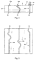
- the shift drum 2 is shown in a view. From this illustration becomes the undulating course of differently designed cam tracks 11a to 11d visible.
- this comprises a cylindrical base body 23 on which walls 9, 10 axially spaced from each other to form a desired curved path 11a up to 11 d are arranged in a wave shape on the circumference.
- walls 9, 10 can, for example, have square or rectangular continuous profiles are used, which are cut to length and profiled in a wavy shape the lateral surface 8 are attached.
- the shift drum 32 is shown, which is an alternative to the shift drum 2 shown in FIG.
- the cam tracks 33a to 33c are each formed by only one wall 30, preferably through a profile strand with a square or rectangular Cross-section.
- To guide the driver 13 these are with a provided fork-shaped projection 31 which engages around the wall 30. So that results a component-optimized and weight-reduced driver guide.
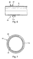
- FIG. 6 shows an alternatively designed cam track 11 a, which is formed is by a U-shaped profile 25 which is wavy on the outer surface 8 of the shift drum 2 is arranged.
- the driver 13 of the shift fork 12a to 12c (see Figure 1) is guided on walls 26, 27 of the profile 25, the Spacing is adapted to the diameter of the guide element 14.
- FIG. 7 shows the shift drum 22, which is designed in a two-shell construction displayed.
- the base body 23 is accordingly of a cylindrical sleeve 28 enclosed, in which the cam track 11a is introduced.
- This structure enables the prefabrication of a sleeve 28 with all the required curved paths 11 a to 11 d is provided. Furthermore, this structure offers one Gearbox manufacturer who needs different shift drums, a cost reduction and an increase in identical parts, since the basic body 23 is the same Type can be used, which can be combined with different sleeves 28 are.
- This enables weight optimization or noise reduction Design, the use of different materials for the sleeve 28 and the base body 23. Then it makes sense to close the sleeve made of sheet steel manufacture the insoluble on a base made of plastic is arranged. Such a pairing of materials has a positive influence the noise level associated with the shift drum 22 Components.
Landscapes
- Engineering & Computer Science (AREA)
- General Engineering & Computer Science (AREA)
- Mechanical Engineering (AREA)
- Gear-Shifting Mechanisms (AREA)
Claims (11)
- Tambour de sélection pour un dispositif de commande d'une boíte de changement de vitesses à engrenages (1) pour véhicules automobiles, où une surface latérale (8) du tambour de forme cylindrique (2, 22) présente au moins un chemin curviligne (11a à 11d) pour le guidage par liaison par forme d'un entraíneur (13) d'une fourchette de sélection (12a à 12c), la fourchette de sélection (12a à 12c) étant reliée à un manchon coulissant d'un synchroniseur qui est disposé sur un arbre de transmission placé parallèlement au tambour de sélection (2, 22) de manière à pouvoir coulisser entre deux roues dentées, caractérisé en ce que le tambour de sélection (2) comprend un cylindre creux de forme tubulaire en une pièce, appelé corps de base (23) et réalisé en tôle d'acier, sur la surface latérale (8) duquel au moins une paroi, réalisée en tant que composant distinct, et orientée vers l'extérieur radialement (9, 10, 26, 27, 30) a été disposée afin de former le chemin curviligne (11a à 11d ; 33a à 33c).
- Tambour de sélection selon le préambule de la revendication 1, caractérisé par un mode de construction en deux phases du tambour de sélection (22) qui comprend un corps de base (23) qui est entouré coaxialement par une douille en forme de cylindre creux (28) présentant au moins un chemin curviligne (11a à 11c), qui, dans une position finale, est assemblée de manière non démontable au corps de base (23), le tambour de sélection (22) et la douille (28) étant réalisés dans des matériaux différents.
- Tambour de sélection selon la revendication 1, caractérisé en ce que le chemin curviligne (11a à 11d) comprend deux parois (9, 10 ; 26, 27) écartées l'une de l'autre.
- Tambour de sélection selon la revendication 1, caractérisé en ce que le chemin curviligne (33a à 33c) est constitué d'une paroi (30) qui est entourée par un embout en forme de fourchette (31) de l'entraíneur (13).
- Tambour de sélection selon la revendication 1, caractérisé en ce que des disques perforés profilés en forme d'onde sont prévus en tant que chemin curviligne, lesquels disques, préfabriqués selon une forme correspondant au chemin curviligne (11a à 11d), sont disposés, par paire, sur le corps de base cylindrique (23) .
- Tambour de sélection selon la revendication 1, caractérisé en ce qu'un profilé à quatre pans de forme rectangulaire ou quadratique ou un profilé rond est fixé, par paire, sur le corps de base (23) afin de former le chemin curviligne (11a à 11d).
- Tambour de sélection selon la revendication 1, caractérisé en ce qu'un profilé en une pièce en forme de U (25) sert à former le chemin curviligne (11a à 11d), lequel profilé préfabriqué selon une forme correspondante cylindrique, est fixé sur la surface latérale (8).
- Tambour de sélection selon la revendication 1, caractérisé en ce que le chemin curviligne (11a à 11d) est réalisé de manière quasiment fermée dans ses zones terminales (29).
- Tambour de sélection selon la revendication 1 ou la revendication 2, caractérisé en ce qu'il est fermé, en tant que corps de base (23), au moyen de couvercles (3, 4) fabriqués en tôle d'acier au niveau des faces frontales.
- Tambour de sélection selon la revendication 9, caractérisé en ce que des tourillons débordant axialement au centre sont disposés sur les couvercles (3, 4), lesquels, en position de montage, servent de support au tambour de sélection (2) dans un carter (7) de la boíte de changement de vitesses à engrenages (1).
- Tambour de sélection selon la revendication 1, caractérisé en ce que le tambour de sélection (2) est associé à une couronne dentée (19) pourvue d'une denture externe, laquelle est en liaison avec un servomoteur (16) via une roue intermédiaire (18) afin de procurer un dispositif d'entraínement rotatif quand le tambour de sélection (2) est en position de montage.
Applications Claiming Priority (3)
| Application Number | Priority Date | Filing Date | Title |
|---|---|---|---|
| DE19727569A DE19727569A1 (de) | 1997-06-28 | 1997-06-28 | Schaltwalze für ein Zahnräderwechselgetriebe |
| DE19727569 | 1997-06-28 | ||
| PCT/EP1998/003597 WO1999000614A1 (fr) | 1997-06-28 | 1998-06-15 | Tambour selecteur de vitesses pour une boite de vitesses |
Publications (2)
| Publication Number | Publication Date |
|---|---|
| EP0991879A1 EP0991879A1 (fr) | 2000-04-12 |
| EP0991879B1 true EP0991879B1 (fr) | 2004-01-21 |
Family
ID=7833962
Family Applications (1)
| Application Number | Title | Priority Date | Filing Date |
|---|---|---|---|
| EP98936344A Expired - Lifetime EP0991879B1 (fr) | 1997-06-28 | 1998-06-15 | Tambour selecteur de vitesses pour une boite de vitesses |
Country Status (4)
| Country | Link |
|---|---|
| US (1) | US6370976B1 (fr) |
| EP (1) | EP0991879B1 (fr) |
| DE (2) | DE19727569A1 (fr) |
| WO (1) | WO1999000614A1 (fr) |
Families Citing this family (23)
| Publication number | Priority date | Publication date | Assignee | Title |
|---|---|---|---|---|
| DE10013878A1 (de) * | 2000-03-21 | 2001-09-27 | Schaeffler Waelzlager Ohg | Spanlos hergestellte Schaltwelle |
| WO2002038988A1 (fr) * | 2000-11-07 | 2002-05-16 | Luk Lamellen Und Kupplungsbau Beteiligungs Kg | Actionneur a moteur electrique pour boite de vitesses |
| DE10102960A1 (de) * | 2001-01-23 | 2002-08-14 | Ina Schaeffler Kg | Schaltwalze eines Wechselgetriebes |
| DE10236822B4 (de) * | 2002-08-10 | 2009-04-09 | Sander Kg Gmbh & Co. | Verfahren und Vorrichtung zur Herstellung einer Schalttrommel |
| DE10347492A1 (de) * | 2003-10-13 | 2005-06-09 | Zf Friedrichshafen Ag | Schalteinrichtung |
| US20060162487A1 (en) * | 2005-01-25 | 2006-07-27 | Harley-Davidson Motor Company Group, Inc. | Composite shifter cam for a motorcycle transmission |
| TWI293604B (en) * | 2006-07-12 | 2008-02-21 | Ind Tech Res Inst | Parking shift mechanism of vehicles |
| JP4832254B2 (ja) * | 2006-10-31 | 2011-12-07 | 本田技研工業株式会社 | 変速機のリバースインヒビタ機構 |
| CA2572159C (fr) * | 2006-12-20 | 2014-11-25 | Namco Machine & Gear Works Ltd. | Methode de formage d'une boite de vitesses au moyen d'acier profile creux |
| DE102007011281A1 (de) | 2007-03-08 | 2008-09-11 | Schaeffler Kg | Schaltwalze |
| JP4897534B2 (ja) * | 2007-03-28 | 2012-03-14 | 本田技研工業株式会社 | 車両用変速機 |
| DE102008018817A1 (de) | 2008-04-15 | 2009-10-22 | Schaeffler Kg | Führungsrippenaufsatz für eine Walze sowie Schaltwalze mit dem Führungsrippenaufsatz |
| DE102008018813A1 (de) | 2008-04-15 | 2009-10-22 | Schaeffler Kg | Führungsrippenanordnung, Walze mit der Führungsrippenanordnung und Verfahren zur Fertigung |
| US7963183B2 (en) | 2009-04-06 | 2011-06-21 | Dean Pick | Sequential transmission shift system |
| US8402859B2 (en) * | 2009-11-04 | 2013-03-26 | GM Global Technology Operations LLC | Barrel cam shift mechanism |
| EP2322822B1 (fr) * | 2009-11-13 | 2012-03-07 | C.R.F. Società Consortile per Azioni | Transmission à double embrayage de véhicule à moteur avec dispositif de levier de vitesse comportant un tambour rotatif et système de propulsion hybride de véhicule à moteur incluant une telle transmission |
| DE102009056889A1 (de) | 2009-12-10 | 2011-06-30 | Schaeffler Technologies GmbH & Co. KG, 91074 | Schalteinheit |
| DE102012221143A1 (de) | 2011-12-05 | 2013-06-06 | Schaeffler Technologies AG & Co. KG | Schaltanordnung für ein Zahnräderwechselgetriebe |
| DE102011088666A1 (de) * | 2011-12-15 | 2013-06-20 | Zf Friedrichshafen Ag | Verschiebevorrichtung mit mittels Kulissenführung verschiebbarer Schiebemuffe |
| DK3737481T3 (da) | 2018-01-11 | 2022-08-01 | Lego As | Legetøjsgearkasse |
| JP6680823B2 (ja) * | 2018-04-05 | 2020-04-15 | 本田技研工業株式会社 | パワーユニット |
| JP2021014894A (ja) * | 2019-07-12 | 2021-02-12 | 川崎重工業株式会社 | シフトドラム及びアクチュエータユニットを同軸配置した変速機構 |
| DE102021128917B3 (de) * | 2021-11-05 | 2022-08-25 | Markus Schaack | Schaltwalze |
Family Cites Families (14)
| Publication number | Priority date | Publication date | Assignee | Title |
|---|---|---|---|---|
| DE806095C (de) * | 1949-07-15 | 1951-06-11 | Siegfried Eisold Dipl Ing | Schaltvorrichtung fuer Zweiganggetriebe von Kraftraedern |
| DE1202665B (de) * | 1962-11-27 | 1965-10-07 | Steyr Daimler Puch Ag | Schalteinrichtung fuer Motorradgetriebe |
| US4635506A (en) * | 1982-10-15 | 1987-01-13 | Honda Giken Kogyo Kabushiki Kaisha | Gearbox assembly for vehicles |
| JPS59140127A (ja) * | 1983-01-31 | 1984-08-11 | Yamaha Motor Co Ltd | 自動三輪車等の変速装置 |
| JPS6026857A (ja) | 1983-07-20 | 1985-02-09 | Koyo Seiki Kk | チエンジドラムの製造方法 |
| JPS6026858A (ja) * | 1983-07-20 | 1985-02-09 | Koyo Seiki Kk | チエンジドラムの製造方法 |
| JP2559027B2 (ja) | 1986-03-22 | 1996-11-27 | ヤマハ発動機株式会社 | 変速機のシフトドラム |
| DE4214136C2 (de) * | 1992-04-29 | 1995-09-21 | Daimler Benz Aerospace Ag | Zweiachsig messender Sonnensensor |
| FR2712654B1 (fr) * | 1993-11-18 | 1996-01-12 | Smh Management Services Ag | Boîte de vitesses. |
| DE19509477B4 (de) * | 1995-03-16 | 2007-08-30 | Adam Opel Ag | Schaltvorrichtung für ein Geschwindigkeits-Wechselgetriebe |
| DE19528460A1 (de) * | 1995-03-29 | 1996-10-02 | Mann & Hummel Filter | Kunststoffelement |
| DE19612690C1 (de) * | 1996-03-29 | 1997-06-12 | Mc Micro Compact Car Ag | Zahnräderwechselgetriebe für ein Kraftfahrzeug |
| DE19713423C5 (de) * | 1996-04-03 | 2015-11-26 | Schaeffler Technologies AG & Co. KG | Vorrichtung und Verfahren zur Betätigung eines Getriebes |
| IT1289758B1 (it) * | 1996-12-17 | 1998-10-16 | Magneti Marelli Spa | Dispositivo di comando per un cambio di velocita' di un veicolo. |
-
1997
- 1997-06-28 DE DE19727569A patent/DE19727569A1/de not_active Withdrawn
-
1998
- 1998-06-15 WO PCT/EP1998/003597 patent/WO1999000614A1/fr not_active Ceased
- 1998-06-15 DE DE59810633T patent/DE59810633D1/de not_active Expired - Lifetime
- 1998-06-15 EP EP98936344A patent/EP0991879B1/fr not_active Expired - Lifetime
- 1998-06-15 US US09/446,430 patent/US6370976B1/en not_active Expired - Lifetime
Also Published As
| Publication number | Publication date |
|---|---|
| US6370976B1 (en) | 2002-04-16 |
| DE59810633D1 (de) | 2004-02-26 |
| EP0991879A1 (fr) | 2000-04-12 |
| WO1999000614A1 (fr) | 1999-01-07 |
| DE19727569A1 (de) | 1999-01-07 |
Similar Documents
| Publication | Publication Date | Title |
|---|---|---|
| EP0991879B1 (fr) | Tambour selecteur de vitesses pour une boite de vitesses | |
| EP0985857B1 (fr) | Manchon d'immobilisation d'un arbre de commande | |
| EP1561055B1 (fr) | Dispositif de changement de vitesse pour boite de vitesses | |
| EP0741258B1 (fr) | Dispositif de transmission à changement de rapport | |
| DE69022767T2 (de) | Schaltmechanismus mit einer einzigen Schaltstange. | |
| EP0875689B1 (fr) | Dispositif de synchronisation | |
| EP1616116B1 (fr) | Boite de vitesses multi-etagee pour moteur a combustion interne | |
| DE19924335B4 (de) | Stellvorrichtung und Stufengetriebe mit Stellvorrichtung für ein Kraftfahrzeug | |
| DE3116383C2 (de) | Fahrzeuggetriebe | |
| DE102008031313A1 (de) | Schaltanordnung für ein Kraftfahrzeug-Wechselgetriebe | |
| WO1999000614B1 (fr) | Tambour selecteur de vitesses pour une boite de vitesses | |
| EP2232107B1 (fr) | Dispositif de changement de vitesse pour boîtes de vitesses à plusieurs étages de véhicules automobiles | |
| DE3536088C2 (fr) | ||
| DE69707542T2 (de) | Einwellenschaltvorrichtung | |
| EP1272780B1 (fr) | Fourchette de selection pour une boite de vitesses a engrenages | |
| DE102012200185A1 (de) | Befestigungsstruktur für Ausgangsritzel | |
| DE69404767T2 (de) | Anlasser für Verbrennungsmotor | |
| DE60014277T2 (de) | Schaltgabel für Getriebe eines Kraftfahrzeuges | |
| EP1333200B1 (fr) | Dispositif de changement de vitesses pour transmission à engrenages droits | |
| DE69304213T2 (de) | Innere Schalteinheit von einem Gangschaltmechanismus | |
| EP1828647B1 (fr) | Systeme de changement de vitesses | |
| DE19645791A1 (de) | Spanlos hergestellte Schaltwalze für ein Zahnräderwechselgetriebe | |
| EP2179200B1 (fr) | Dispositif de passage des vitesses pour une boîte de vitesses d'un véhicule motorisé comportant un dispositif de verrouillage | |
| AT509880B1 (de) | Schaltelement, schaltvorrichtung und verfahren zu deren herstellung | |
| DE102005053989B4 (de) | Verfahren zur Herstellung eines Kupplungskörpers |
Legal Events
| Date | Code | Title | Description |
|---|---|---|---|
| PUAI | Public reference made under article 153(3) epc to a published international application that has entered the european phase |
Free format text: ORIGINAL CODE: 0009012 |
|
| 17P | Request for examination filed |
Effective date: 19991119 |
|
| AK | Designated contracting states |
Kind code of ref document: A1 Designated state(s): DE FR GB IT SE |
|
| RAP1 | Party data changed (applicant data changed or rights of an application transferred) |
Owner name: INA-SCHAEFFLER KG |
|
| 17Q | First examination report despatched |
Effective date: 20020813 |
|
| GRAP | Despatch of communication of intention to grant a patent |
Free format text: ORIGINAL CODE: EPIDOSNIGR1 |
|
| GRAS | Grant fee paid |
Free format text: ORIGINAL CODE: EPIDOSNIGR3 |
|
| GRAA | (expected) grant |
Free format text: ORIGINAL CODE: 0009210 |
|
| AK | Designated contracting states |
Kind code of ref document: B1 Designated state(s): DE FR GB IT SE |
|
| REG | Reference to a national code |
Ref country code: GB Ref legal event code: FG4D Free format text: NOT ENGLISH |
|
| REF | Corresponds to: |
Ref document number: 59810633 Country of ref document: DE Date of ref document: 20040226 Kind code of ref document: P |
|
| REG | Reference to a national code |
Ref country code: SE Ref legal event code: TRGR |
|
| GBT | Gb: translation of ep patent filed (gb section 77(6)(a)/1977) |
Effective date: 20040407 |
|
| ET | Fr: translation filed | ||
| PLBE | No opposition filed within time limit |
Free format text: ORIGINAL CODE: 0009261 |
|
| STAA | Information on the status of an ep patent application or granted ep patent |
Free format text: STATUS: NO OPPOSITION FILED WITHIN TIME LIMIT |
|
| 26N | No opposition filed |
Effective date: 20041022 |
|
| PGFP | Annual fee paid to national office [announced via postgrant information from national office to epo] |
Ref country code: GB Payment date: 20070613 Year of fee payment: 10 |
|
| PGFP | Annual fee paid to national office [announced via postgrant information from national office to epo] |
Ref country code: IT Payment date: 20080626 Year of fee payment: 11 |
|
| PGFP | Annual fee paid to national office [announced via postgrant information from national office to epo] |
Ref country code: SE Payment date: 20080609 Year of fee payment: 11 |
|
| PGFP | Annual fee paid to national office [announced via postgrant information from national office to epo] |
Ref country code: FR Payment date: 20080617 Year of fee payment: 11 |
|
| GBPC | Gb: european patent ceased through non-payment of renewal fee |
Effective date: 20080615 |
|
| PG25 | Lapsed in a contracting state [announced via postgrant information from national office to epo] |
Ref country code: GB Free format text: LAPSE BECAUSE OF NON-PAYMENT OF DUE FEES Effective date: 20080615 |
|
| REG | Reference to a national code |
Ref country code: FR Ref legal event code: ST Effective date: 20100226 |
|
| PG25 | Lapsed in a contracting state [announced via postgrant information from national office to epo] |
Ref country code: FR Free format text: LAPSE BECAUSE OF NON-PAYMENT OF DUE FEES Effective date: 20090630 |
|
| PG25 | Lapsed in a contracting state [announced via postgrant information from national office to epo] |
Ref country code: IT Free format text: LAPSE BECAUSE OF NON-PAYMENT OF DUE FEES Effective date: 20090615 |
|
| PG25 | Lapsed in a contracting state [announced via postgrant information from national office to epo] |
Ref country code: SE Free format text: LAPSE BECAUSE OF NON-PAYMENT OF DUE FEES Effective date: 20090616 |
|
| REG | Reference to a national code |
Ref country code: DE Ref legal event code: R081 Ref document number: 59810633 Country of ref document: DE Owner name: SCHAEFFLER TECHNOLOGIES GMBH & CO. KG, DE Free format text: FORMER OWNER: SCHAEFFLER TECHNOLOGIES GMBH & CO. KG, 91074 HERZOGENAURACH, DE Effective date: 20120828 Ref country code: DE Ref legal event code: R081 Ref document number: 59810633 Country of ref document: DE Owner name: SCHAEFFLER TECHNOLOGIES AG & CO. KG, DE Free format text: FORMER OWNER: SCHAEFFLER TECHNOLOGIES GMBH & CO. KG, 91074 HERZOGENAURACH, DE Effective date: 20120828 |
|
| REG | Reference to a national code |
Ref country code: DE Ref legal event code: R081 Ref document number: 59810633 Country of ref document: DE Owner name: SCHAEFFLER TECHNOLOGIES AG & CO. KG, DE Free format text: FORMER OWNER: SCHAEFFLER TECHNOLOGIES AG & CO. KG, 91074 HERZOGENAURACH, DE Effective date: 20140218 Ref country code: DE Ref legal event code: R081 Ref document number: 59810633 Country of ref document: DE Owner name: SCHAEFFLER TECHNOLOGIES GMBH & CO. KG, DE Free format text: FORMER OWNER: SCHAEFFLER TECHNOLOGIES AG & CO. KG, 91074 HERZOGENAURACH, DE Effective date: 20140218 |
|
| REG | Reference to a national code |
Ref country code: DE Ref legal event code: R081 Ref document number: 59810633 Country of ref document: DE Owner name: SCHAEFFLER TECHNOLOGIES AG & CO. KG, DE Free format text: FORMER OWNER: SCHAEFFLER TECHNOLOGIES GMBH & CO. KG, 91074 HERZOGENAURACH, DE Effective date: 20150210 |
|
| PGFP | Annual fee paid to national office [announced via postgrant information from national office to epo] |
Ref country code: DE Payment date: 20160831 Year of fee payment: 19 |
|
| REG | Reference to a national code |
Ref country code: DE Ref legal event code: R119 Ref document number: 59810633 Country of ref document: DE |
|
| PG25 | Lapsed in a contracting state [announced via postgrant information from national office to epo] |
Ref country code: DE Free format text: LAPSE BECAUSE OF NON-PAYMENT OF DUE FEES Effective date: 20180103 |
|
| P01 | Opt-out of the competence of the unified patent court (upc) registered |
Effective date: 20230522 |