EP0991969B1 - Contenant a ferrules et dispositif servant a assembler des fibres optiques multiples - Google Patents
Contenant a ferrules et dispositif servant a assembler des fibres optiques multiples Download PDFInfo
- Publication number
- EP0991969B1 EP0991969B1 EP98934833A EP98934833A EP0991969B1 EP 0991969 B1 EP0991969 B1 EP 0991969B1 EP 98934833 A EP98934833 A EP 98934833A EP 98934833 A EP98934833 A EP 98934833A EP 0991969 B1 EP0991969 B1 EP 0991969B1
- Authority
- EP
- European Patent Office
- Prior art keywords
- ferrule
- housing
- container
- locking means
- constructed
- Prior art date
- Legal status (The legal status is an assumption and is not a legal conclusion. Google has not performed a legal analysis and makes no representation as to the accuracy of the status listed.)
- Expired - Lifetime
Links
- 239000013307 optical fiber Substances 0.000 title claims description 20
- 230000003287 optical effect Effects 0.000 claims description 29
- 239000000835 fiber Substances 0.000 description 19
- 238000012856 packing Methods 0.000 description 10
- 210000002105 tongue Anatomy 0.000 description 10
- 230000006835 compression Effects 0.000 description 8
- 238000007906 compression Methods 0.000 description 8
- 230000005540 biological transmission Effects 0.000 description 5
- 238000003780 insertion Methods 0.000 description 3
- 230000037431 insertion Effects 0.000 description 3
- 238000000926 separation method Methods 0.000 description 3
- 230000009471 action Effects 0.000 description 2
- 238000013461 design Methods 0.000 description 2
- 230000003993 interaction Effects 0.000 description 2
- 238000000034 method Methods 0.000 description 2
- 230000008569 process Effects 0.000 description 2
- XOMKZKJEJBZBJJ-UHFFFAOYSA-N 1,2-dichloro-3-phenylbenzene Chemical compound ClC1=CC=CC(C=2C=CC=CC=2)=C1Cl XOMKZKJEJBZBJJ-UHFFFAOYSA-N 0.000 description 1
- 238000003491 array Methods 0.000 description 1
- 230000000712 assembly Effects 0.000 description 1
- 238000000429 assembly Methods 0.000 description 1
- 238000005452 bending Methods 0.000 description 1
- 230000008901 benefit Effects 0.000 description 1
- 238000010276 construction Methods 0.000 description 1
- 230000007246 mechanism Effects 0.000 description 1
- BASFCYQUMIYNBI-UHFFFAOYSA-N platinum Chemical compound [Pt] BASFCYQUMIYNBI-UHFFFAOYSA-N 0.000 description 1
- 238000004321 preservation Methods 0.000 description 1
- 238000012549 training Methods 0.000 description 1
- 230000007704 transition Effects 0.000 description 1
- 230000000007 visual effect Effects 0.000 description 1
Images


Classifications
-
- G—PHYSICS
- G02—OPTICS
- G02B—OPTICAL ELEMENTS, SYSTEMS OR APPARATUS
- G02B6/00—Light guides; Structural details of arrangements comprising light guides and other optical elements, e.g. couplings
- G02B6/24—Coupling light guides
- G02B6/36—Mechanical coupling means
- G02B6/38—Mechanical coupling means having fibre to fibre mating means
- G02B6/3807—Dismountable connectors, i.e. comprising plugs
- G02B6/3873—Connectors using guide surfaces for aligning ferrule ends, e.g. tubes, sleeves, V-grooves, rods, pins, balls
- G02B6/3885—Multicore or multichannel optical connectors, i.e. one single ferrule containing more than one fibre, e.g. ribbon type
-
- G—PHYSICS
- G02—OPTICS
- G02B—OPTICAL ELEMENTS, SYSTEMS OR APPARATUS
- G02B6/00—Light guides; Structural details of arrangements comprising light guides and other optical elements, e.g. couplings
- G02B6/24—Coupling light guides
- G02B6/36—Mechanical coupling means
- G02B6/38—Mechanical coupling means having fibre to fibre mating means
- G02B6/3807—Dismountable connectors, i.e. comprising plugs
- G02B6/3873—Connectors using guide surfaces for aligning ferrule ends, e.g. tubes, sleeves, V-grooves, rods, pins, balls
- G02B6/3874—Connectors using guide surfaces for aligning ferrule ends, e.g. tubes, sleeves, V-grooves, rods, pins, balls using tubes, sleeves to align ferrules
- G02B6/3878—Connectors using guide surfaces for aligning ferrule ends, e.g. tubes, sleeves, V-grooves, rods, pins, balls using tubes, sleeves to align ferrules comprising a plurality of ferrules, branching and break-out means
- G02B6/3879—Linking of individual connector plugs to an overconnector, e.g. using clamps, clips, common housings comprising several individual connector plugs
-
- G—PHYSICS
- G02—OPTICS
- G02B—OPTICAL ELEMENTS, SYSTEMS OR APPARATUS
- G02B6/00—Light guides; Structural details of arrangements comprising light guides and other optical elements, e.g. couplings
- G02B6/24—Coupling light guides
- G02B6/36—Mechanical coupling means
- G02B6/38—Mechanical coupling means having fibre to fibre mating means
- G02B6/3807—Dismountable connectors, i.e. comprising plugs
- G02B6/3897—Connectors fixed to housings, casing, frames or circuit boards
Definitions
- the invention relates to a ferrule container for receiving an optical multiple fiber arranged in a ferrule.
- the invention further relates to a connection arrangement for connecting optical multiple fibers.
- connection arrangement which is particularly for modular electronic devices with several, in essentially parallel PCB slots can be used by a common carrier board or a so-called backplane board can be worn and over these visually and with each other and to the outside are optionally also electrically connectable.
- ferrule container solved according to claim 1 and with a connection arrangement according to claim 12.
- the ferrule container is designed that several each arranged in ferrules optical fibers are recordable. By this design lets achieve a high packing density because of the connection several optical multiple fibers already one Ferrule container is sufficient. Both are advantageous Ferrules with multiple fibers as well as ferrules with Single fibers together in the invention Ferrule container can be accommodated. Finally, it is also conceivably both optical and electrical connections to accommodate together in a ferrule container.
- the ferrule container according to the invention advantageously has Ferrule shafts extending parallel to one another to accommodate the ferrules, the Ferrule shafts each have at least one that can be actuated Ferrule holding device for fixing the ferrules exhibit.
- the ferrule holding device is divided into one Ferrule shaft mountable spring holder, in a compression spring as well as in spring retainer lugs provided in the receiving shaft, the spring holder locking lugs advantageously are designed to be actuated.
- a ferrule is particularly easy to use Fasten the ferrule container, by providing a a play compensation on the compression spring acting on the ferrule is guaranteed.
- the compression spring is so between the Ferrule and the spring holder arranged that the ferrule through the compression spring is pressed against a stop in the ferrule shaft becomes.
- the free front end of the ferrule comes with the free one Front end of the optical multiple fibers of another ferrule in contact, the ferrule can prevent the deformation of the Dodge the compression spring back into the ferrule container and compensate for positional inaccuracies in this way.
- the ferrule can be easily removed from the ferrule container be removed.
- the ferrule container designed in this way in a simple manner possible to mount a ferrule in the ferrule container.
- the ferrule container has locking elements on the outside, so are designed so that the ferrule container in one Board housing or in a connection housing in particular is releasably fixable. This can create a firm connection between the ferrule container and a board housing or a connection housing can be achieved. Especially with that Providing a junction box can be done so quickly detachable and reliable connections between optical Multiple fibers with an extremely high packing density to reach.
- the cross section have a rectangular inner shape, preferably two ferrule shafts are arranged so that they are in cross section one of their longer inner edges right next to each other come to rest, then there is a ferrule container with a particularly high packing density. Doing the ferrule container in cross-section essentially one square outer shape. This allows a standardized Execution of the ferrule container according to the invention achieve so that there are modular connection arrangements can be put together easily.
- Ferrule container coding elements on the outside of the ferrule container are provided, which are designed so that with them an insertion orientation of the ferrule container in in a board housing or in a connection housing is definable. This allows assembly errors from Avoid in a simple way beforehand, if already at the Designing a connection arrangement the right one Orientation is determined.
- the ferrule container can also be trained in cross-section have a rectangular outer shape. This will keep from a total of four possible positions of the ferrule container in there are only two orientations left for a connecting element, so that a particularly simple coding results.
- ferrule container on the Board side, on the side of the cable connector and / or especially on the side of the - if available - spring holder by providing appropriate coding elements to encode directionally.
- the ferrule container according to the invention in Area of one end face at least one guide hole, in which a guide pin can be inserted. In this way can have multiple ferrules through a single guide pin / guide hole pair aligned with each other.
- connection arrangement With this connection arrangement, a high Packing density with a large margin of tolerance produce. This is especially important for use cases where in a modular device with several PCB slots and a common carrier plate for the printed circuit boards with each other and externally visually and if necessary must also be electrically connectable.
- the expert denotes the level of the carrier plate of the individual Printed circuit boards as a "backplane” while the level of a PCB slots is referred to as a "board”.
- the Invention is based on the essential to the invention Recognition that a separation of the connection arrangement in the components "ferrule container", "board housing” and in that attached in the area of the backplane level “Feed-through housing" for such tolerance compensation is of great importance.
- connection arrangement according to the invention also for reliable and yet quickly releasable flying connection from Multiple optical fibers can be used.
- the connection arrangement Through the Separation of the connection arrangement into ferrule containers, Board cases and bushings can be easily Generated actuatable releasable connection assemblies become.
- connection arrangement is advantageous a releasable first locking device for in particular non-positive connection of the first ferrule container and board case as well as a detachable second Locking device for in particular non-positive Connection of the first ferrule container and Feed-through housing provided.
- “Solvable” here means that between a locked and a released state of the first ferrule container in the board housing or in the Bushing housing can be switched back and forth. At a locked state essentially results in one fixed connection between ferrule container and board housing or bushing housing, while one is detached Condition of the locking device of the ferrule containers inside the board housing or inside the Bushing can move essentially freely.
- connection arrangement there is when the board housing and Bushing the first locking device in released state and the second locking device in locked state while in separate Condition of board housing and bushing housing the first Locking device is in the locked state. In separate state of board housing and Grommet housing occurs the second Locking device not in action.
- the first locking device is advantageous trained so that by movement of the Board housing in the direction away from the bushing housing from can be brought into a locked state from a released state is, which is also automatically in the course of Movement of the board housing can take place. With a movement of the board housing in the direction of the bushing housing against it is the first locking device can advantageously be brought into a released state, wherein also this automatically due to the movement of the Board housing towards the bushing housing can be done.
- the second locking device it is these are preferably designed so that they are replaced by a Movement of the board housing towards Feed-through housing can be brought into a locked state and so that it is a firm connection between the first Ferrule container and lead-through housing created. It is provided that the second locking device automatically goes into a locked state when that Board housing moved towards the bushing housing becomes. In contrast, the second locking device when the board housing moves in the direction of Bushing housing removed in a released state. The above operations of the second locking device are particularly provided so that automatically when the board housing moves respectively.
- first locking device in Area of the snap hook ferrule container as well as in the area of the board housing board housing locking lugs provided. Furthermore, the first locking device in the area of the lead-through housing provided first ejector lugs exhibit. This enables automated actuation or an automated release of the first locking device favored.
- the second locking device in the area of the ferrule container provided snap hooks as well as on the part of the lead-through housing provided with lead-through housing locking lugs have, wherein to solve the second Locking device also in the area of Bushing housing second ejector lugs may be provided can.
- the invention described here enables the construction of a optical connector system with a very high Packing density. It is possible to both the invention run as a stand-alone solution as well as the invention to integrate into existing electrical systems. The Tolerances occurring in electrical connector systems are intercepted so that the for optical connections obligatory tolerances can be met. In addition, the invention offers through its modular and symmetrical structure the possibility of all in practice to be able to cover occurring applications.
- the solution according to the invention provides a connection arrangement ready to meet both the large axial tolerances of several Millimeters for electrical systems as well as the small ones axial tolerances of a few micrometers for optical Is able to ensure connections. This allows even deflections within the backplane compensated be, whereby an extremely high packing density is achieved.
- the invention is in the drawing based on a Embodiment described in more detail.
- Figure 1 shows an exploded perspective Representation of a connection arrangement according to the invention two ferrule containers according to the invention
- FIG. 2 shows a perspective view of the Ferrule container from Figure 1 in more detail
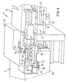
- Figure 3 shows a perspective view of the connection arrangement from Figure 1 in the unplugged state, the Components of the connection arrangement partially cut are shown
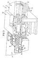
- Figure 4 shows the connection arrangement from Figure 3 in locked state
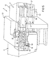
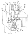
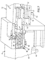
- Figure 5, Figure 6, Figure 7 and Figure 8 show the connection arrangement from Figure 3 in different positions between a released and a locked state.
- FIG. 1 shows a connection arrangement 1 according to the invention exploded perspective view.
- the connection arrangement 1 is divided into a bushing housing 2, which is arranged on a carrier plate 3, in a Board housing 4, which is arranged on a circuit board 5, as well as in a first ferrule container 6 and in one second ferrule container 7.
- the connection arrangement 1 serves for connecting a first multiple optical waveguide 11 with a second multiple optical waveguide 11 'and one third multiple optical fiber 12 with a fourth Multiple optical fibers 12 ', each by only one Line of symmetry are shown.
- the first ferrule container 6 is designed so that it first multiple optical fiber 11 and the third Multiple optical fiber 12 can accommodate.
- first multiple optical fiber 11 and the third Multiple optical fiber 12 are the single fibers at the end of the first multiple optical fiber 11 and at the end of the third multiple optical fiber 12 side by side in a first ferrule 13 and recorded in a second ferrule 14 such that the ends of the individual fibers with a first end face 15 of the first ferrule 13 or with a second end face 16 of the second ferrule 14 flush to lock.
- the first ferrule 13 has two guide pins 17 and wherein the second ferrule 14 also has two guide pins 17 having. Only one of the four is in the drawing Guide pins 17 designated by a reference number.
- the emerging ends of the individual fibers of the first multiple optical waveguide 11 and the third multiple optical fiber 12 are only thin in the drawing Points indicated that are located within the first ferrule 13 and within the second ferrule 14 between each Extend guide pins 17.
- the first ferrule 13 and the second ferrule 14 have in Cross section transverse to the extension of the first multiple optical waveguide 11 and the third multiple optical fiber 12 each have a rectangular cross section.
- the second Multiple optical fiber 11 'and the fourth multiple optical fiber 12 ' also have ferrules that but are not shown in this view.
- the first ferrule container 6 is used to hold the first Ferrule 13 and the second ferrule 14.
- the first Ferrule container 6 has a substantially cuboid shape External shape and has a lower ferrule shaft inside 20 and an upper ferrule shaft 21 as best can be seen in Figure 2.
- the lower ferrule shaft 20 and the upper ferrule shaft 21 extend one above the other in the longitudinal direction of the first ferrule container 6.
- the lower ferrule shaft 20 has a lower ferrule outlet opening 22, while the upper ferrule shaft 21 has an upper ferrule outlet opening 23.
- the function of the detent opening 25 is in connection with a spring holder 26 shown in Figure 1 can be seen.
- the spring holder 26 With an end face 27 each a compression spring 28 in the direction of the outlet openings 21 and 22.
- To fix the spring holder 26 in the first Ferrule containers 6 are two starting from the End face 27 legs 29 extending rearward in a U-shape provided that outward to the boundary wall of the first ferrule container 6 protruding spring holder locking lugs Have 30, of which only an upper in Figure 1 Spring holder latch 30 can be seen.
- the first shows Total ferrule container 6 on its longer outer edges four spring tongues 31, which extend in the longitudinal direction of the Ferrule containers 6 extend and their ends transverse to the Longitudinal directions of the ferrule container 6 are movable.
- snap hooks 32 are provided at the ends of the spring tongues 31, each one to the rear to the detent opening 25 have directed locking edge 33.
- the snap hooks 32 taper towards the front Exit openings 22 and 23 out.
- the snap hooks 32 are designed so that in the idle state shown in FIG is shown, with its outer edges over the outer Surfaces of the lateral boundary surfaces of the first Protruding ferrule containers 6. They are still like this formed that when the snap hook 32 transverse to the longitudinal direction of the first ferrule container 6 Spring tongue 31 yields, so that the snap hook 32 in one Edge opening 34 of the first ferrule container 6 engages.
- the first ferrule container 6 also has one lateral spring tongue 35 with a lateral snap hook 36 on.
- the side snap hook 36 has on its rear End of a side locking edge 37 and runs towards the front tapering.
- the side snap hook 36 protrudes the outer surface of a side boundary wall 38 of the first ferrule container 6 and can be under one of these acting force in one in the side Delimiting wall 38 provided lateral opening 39 be pushed in.
- the snap hooks have the same geometries and Dimensions, however, are on opposite sides appropriate.
- the second ferrule container 7 corresponds essentially to that first ferrule container 6. As shown in the illustration in Figure 2 sees best, the second ferrule container 7th but no lower or upper ferrule shaft, rather, a left ferrule shaft 40 and one right ferrule shaft 41.
- the left ferrule shaft 40 and the right ferrule shaft 41 correspond in terms of Dimensions of the lower ferrule shaft 20 and the upper Ferrule shaft 21, but they are in terms of their Alignment with the longitudinal axis of the second Ferrule container 7 by 90 ° with respect to the orientation of the lower ferrule shaft 20 and the upper ferrule shaft 21 rotated.
- the same components are the same Ferrule container 7 given the same reference numerals as the first ferrule container 6.
- the second one Ferrule container 7 has a lateral boundary wall 38, one side spring tongue with one side Snap hook and a side locking edge which the lateral spring tongue 35, the lateral snap hook 36 and the lateral locking edge 37 of the first ferrule container 6 in terms of location and orientation and dimensions correspond identically.
- the upper boundary wall 24 of the second ferrule container 7 has none Latch opening. This latch opening of the second Rather, ferrule container 7 is located on one corresponding position in the lateral boundary wall 38 as well as in the other boundary wall opposite of the second ferrule container 7. Because of the special Arrangement of the lateral spring tongues 35 in the first Ferrule container 6 and 7 in the second ferrule container whose orientation-based coding causes.
- the on-board housing 4 can best be seen in FIG. 1.
- the On-board housing 4 is an essentially cuboid housing formed the one upper wall 42 and two to each other has symmetrical side walls 43. At the bottom of one bottom wall 44 four plug pins 45 are formed with which the on-board housing 4 in corresponding openings in the Printed circuit board 5 is firmly pressed.
- the end walls of the Board housing 4 are open on both sides, the inside the on-board housing 4 and from the walls 42, 43 and 44 enclosed cavity by a central wall 46 into a first through channel 47 and into a second Through channel 48 is divided.
- the first through channel 47 and the second through channel 48 are of dimensions ago held so that the first ferrule container 6 in the first Through channel 47 is receivable, while the second Ferrule container 7 can be accommodated in the second through channel 48 is.
- lateral locking lug openings 49 provided, of which in the view in Figure 1 only lateral detent opening 49 of the first through-channel 47 you can see.
- the lateral locking lug openings 49 are designed such that them with the first and second state in place Ferrule containers 6 and 7 with the side snap hooks 36 work together.
- the on-board housing ejector structure 50 designed so that when inserted State of the first and second ferrule containers 6, 7 in the first through channel 47 and into the second through channel 48 cooperates with the snap hooks 32 located above.
- the bushing housing 2 is divided into a ferrule area 51 and in a board receiving area 52, each seen as a cuboid outer shape of different sizes.
- the ferrule area 51 for receiving the second multiple optical waveguide 11 'and the third multiple optical waveguide 12' is, in cross section transverse to the course of the multiple optical fibers 11 'and 12' kept smaller than the board receiving area 52.
- the carrier plate 3 has a substantially rectangular opening on, the outline of which essentially corresponds to the external dimensions of the Ferrule area 51 coincides. This is the passage of the ferrule region 51 through the carrier plate 3 guaranteed.
- this shows Feed-through housing 2 on the inside feed-through locking lugs 54 and three feed-through ejector structures 55 on, from which can only be seen in FIG. 3 because the symmetrically opposite other feed-through ejector structure is covered by other components. Between these outside lead-through ejector structures 55 there is still a central bushing ejector structure that for releasing the "inside" snap hooks Ferrule container ensures.
- the bushing locking lugs 54 act with appropriate snap hooks on the edges of the Ferrule containers 6, 7 together while the feed-through ejector structure 55 on the side snap hooks 36 of the Ferrule container 6, 7 acts.
- FIG. 3 In the illustration in figure 3 is a third ferrule 56 in the ferrule region 51 shown inserted, the third ferrule 56 also cut longitudinally in the area of a guide bore 57 is shown.
- the guide bore 57 takes when assembled State of the third ferrule 56 with the first Ferrule 13 has a guide pin 17 so that the front ends the third ferrule 56 and the first ferrule 13 exactly to each other are positioned, which results in a low insertion loss the optical connection of the individual fibers of the optical fibers 11 and 11 'guaranteed.
- FIG 3 shows the assembled system of the connection arrangement 1 from Figure 1 in a still unplugged state. There cuts have been introduced to illustrate the processes can.
- the ferrule container 6 is in this state with the side snap hooks 36 in the side Locking nose openings 49 of the board housing 4 locked.
- Feed-through ejector structures 55 straight in this state on the side snap hooks 36 of the ferrule container 6 on.
- the board housing ejector structures 50 lie in this State just on the snap hooks 32 of the ferrule container 6, 7, which, however, cannot be seen in FIG. 4.
- FIG. 7 shows the case of a maximum further movement of the Board housing 4 in the direction of the bushing 2.
- the board housing 4 moves together with the circuit board 5 in a direction from Feed-through housing 2 away.
- the board housing ejector structures occur with in the area of the snap hooks 32 provided starting paragraphs 58 in contact so that the Snap hook 32 while bending the spring clip 31 inwards can be pressed, as best seen in Figure 8. As a result, the snap hooks 32 detach from the lead-through latches 54.
- the side snap hooks 36 lie with one forward section 59 on a corresponding wall the side locking lug opening 49, which prevents the ferrule container 6 when pulling out the board housing 4 from the bushing housing 2 in the bushing housing 2 remains. Rather, when pulling out the board case 4 in the state shown in Figure 8 due to the Interaction of paragraph 59 with the lateral Latch opening 49 of the ferrule container 6 with the Board housing 4 moved. After pulling out the Board housing 4 from the bushing 2 is located the connection arrangement 1 again in that shown in Figure 3 Status.
- connection arrangement 1 Another advantage of the connection arrangement 1 is in that the position of the ferrules 13, 14 and 56 after Lock regardless of the position of the circuit board 5 is held to each other with respect to the support plate 3. On in this way, the compression springs 28 Tolerance distance to be compensated to a defined maximum value set.
- connection arrangement 1 can be used achieve high packing densities.
Landscapes
- Physics & Mathematics (AREA)
- General Physics & Mathematics (AREA)
- Optics & Photonics (AREA)
- Mechanical Coupling Of Light Guides (AREA)
Claims (24)
- Conteneur de ferrules (6, 7) destiné à recevoir plusieurs fibres optiques multiples (11, 12) agencées respectivement dans des ferrules (13, 14),des cavités à ferrules à extension parallèle (20, 21; 40, 41) étant destinées à recevoir les ferrules (13, 14),les cavités à ferrules (20, 21; 40, 41) comportant au moins un dispositif de retenue des ferrules en particulier à actionnement (25, 26, 28, 30) pour fixer les ferrules (13, 14),le dispositif de retenue des ferrules étant subdivisé en un support de ressort (26) pouvant être reçu dans une cavité à ferrules (20, 21; 40, 41), en un ressort de pression (28) ainsi qu'en des pattes d'arrêt du support de ressort (30) agencées dans une cavité à ferrules ou dans un support de ressort (26) et en des pattes d'arrêt du support de ressort (30) s'engageant dans des ouvertures des pattes d'arrêt (25) agencées dans la cavité à ferrules (20, 21; 40, 41) ou sur le support de ressort, le support de ressort pouvant comporter en particulier un codage d'orientation par l'intermédiaire de l'agencement des ouvertures des pattes d'arrêt (25) et des pattes d'arrêt du support de ressort (30).
- Conteneur de ferrules selon la revendication 1, caractérisé en ce que les pattes d'arrêt du support de ressort (30) ont une configuration à actionnement.
- Conteneur de ferrules selon l'une des revendications précédentes, caractérisé en ce que des éléments de verrouillage (32, 36) sont agencés à l'extérieur et configurés de sorte que le conteneur de ferrules (6, 7) peut être fixé dans un boítier de plaquette (4) ou dans un boítier de connexion (2).
- Conteneur de ferrules selon la revendication 3, caractérisé en ce que les éléments de verrouillage (32, 36) sont configurés de sorte que le conteneur de ferrules (6, 7) peut être fixé de manière amovible.
- Conteneur de ferrules selon l'une des revendications précédentes, caractérisé en ce que:il comporte plusieurs cavités à ferrules (20, 21; 40, 41),les cavités à ferrules (20, 21; 40, 41) ont une forme interne essentiellement rectangulaire en section transversale.
- Conteneur à ferrules selon la revendication 5, caractérisé en ce que deux cavités à ferrules (20, 21; 40, 41) sont agencées de sorte à être directement juxtaposées, respectivement en section transversale d'un de leurs bords internes plus longs.
- Conteneur de ferrules selon l'une des revendications 1 à 6, caractérisé en ce que le conteneur de ferrules a une forme externe essentiellement carrée en section transversale.
- Conteneur de ferrules selon la revendication 7, caractérisé en ce que des éléments de codage du conteneur de ferrules sont agencés sur le côté externe du conteneur de ferrules et configurés de sorte à permettre la fixation d'une orientation d'insertion du conteneur de ferrules dans un boítier de plaquette ou dans un boítier de connexion.
- Conteneur de ferrules selon l'une des revendications 1 à 8, caractérisé en ce que le conteneur de ferrules a une forme externe rectangulaire en section transversale.
- Conteneur de ferrules selon l'une des revendications précédentes, caractérisé en ce qu'un blindage contre les influences électromagnétiques est agencé dans la région des cavités à ferrules et/ou du côté externe du conteneur de ferrules.
- Conteneur de ferrules selon l'une des revendication précédentes, caractérisé en ce qu'au moins un alésage de guidage, dans lequel peut être insérée une broche de guidage est agencé dans la région d'un côté frontal du conteneur de ferrules.
- Assemblage de connexion pour connecter des fibres optiques, caractérisé en ce qu'il comportes:au moins un premier conteneur de ferrules (6, 7) selon la revendication 1, destiné à recevoir au moins une fibre optique multiple (11, 12) agencée dans une première ferrule (13, 14),au moins un boítier de plaquette (4), pouvant en particulier être agencée sur une platine (5) pour recevoir le premier conteneur de ferrules (6, 7),au moins un boítier de passage, agencé en particulier sur un fond de panier (3), pour recevoir au moins une deuxième fibre optique multiple (11') agencée dans une deuxième ferrule (56),le boítier de plaquette (4) et le boítier de passage (2) ayant une configuration à connexion telle qu'un côté frontal (15, 16) de la première ferrule (13, 14) est adjacent à un côté frontal de la deuxième ferrule (56), le premier conteneur de ferrules (6, 7), le boítier de plaquette (4) et le boítier de passage (2) étant en outre configurés de sorte que dans l'état connecté du boítier de plaquette (4) et du boítier de passage (2) il existe une connexion entre la première ferrule (13, 14) et la deuxième ferrule (56),un premier dispositif de verrouillage à dégagement (36, 49) destiné à connecter le premier conteneur de ferrules (6, 7) et le boítier de plaquette (4), et un deuxième dispositif de verrouillage à dégagement (32, 54) pour connecter le premier conteneur de ferrules (6, 7) et le boítier de passage (2),le premier dispositif de verrouillage étant configuré de sorte que dans l'état connecté du boítier de plaquette (4) et du boítier de passage (2) le premier dispositif de verrouillage (36, 49) se trouve dans l'état dégagé, le deuxième dispositif de verrouillage (32, 54) se trouvant dans l'état verrouillé,et/ou le premier dispositif de verrouillage (36, 49) se trouve dans l'état verrouillé lorsque le boítier de plaquette (4) et le boítier de passage (2) sont séparés.
- Assemblage de connexion selon la revendication 12, caractérisé en ce que le premier dispositif de verrouillage (36, 49) est configuré de sorte qu'un déplacement du boítier de plaquette (4) dans une direction l'écartant du boítier de passage (2) le place d'un état dégagé dans un état verrouillé.
- Assemblage de connexion selon la revendication 13, caractérisé en ce que le premier dispositif de verrouillage (36, 49) est configuré de sorte qu'au cours d'un déplacement du boítier de plaquette (4) dans une direction l'écartant du boítier de passage (2) il est placé automatiquement dans un état verrouillé.
- Assemblage de connexion selon l'une des revendications 12 à 14, caractérisé en ce que le premier dispositif de verrouillage (36, 49) est configuré de sorte qu'au cours d'un déplacement du boítier de plaquette (4) en direction du boítier de passage (2) il peut être mis dans un état dégagé.
- Assemblage de connexion selon la revendication 15, caractérisé en ce que le premier dispositif de verrouillage (36, 49) est configuré de sorte qu'au cours d'un déplacement du boítier de plaquette (4) en direction du boítier de passage (2), il passe automatiquement dans un état dégagé.
- Assemblage de connexion selon l'une des revendications 12 à 16, caractérisé en ce que le deuxième dispositif de verrouillage (32, 54) est configuré de sorte qu'au cours d'un déplacement du boítier de plaquette (4) en direction du boítier de passage (2) il peut être mis dans un état verrouillé.
- Assemblage de connexion selon la revendication 17, caractérisé en ce que le deuxième dispositif de verrouillage (32, 54) est configuré de sorte qu'au cours d'un déplacement du boítier de plaquette (4) en direction du boítier de passage (2) il passe automatiquement dans un état verrouillé.
- Assemblage de connexion selon l'une des revendications 12 à 18, caractérisé en ce que le deuxième dispositif de verrouillage (32, 54) est configuré de sorte que lors d'un déplacement du boítier de plaquette (4) à l'écart du boítier de passage (2) il peut être mis dans un état dégagé.
- Assemblage de connexion selon la revendication 19, caractérisé en ce que le premier dispositif de verrouillage (36, 49) est configuré de sorte que lors d'un déplacement du boítier de plaquette (4) à l'écart du boítier de passage (2), il passe automatiquement dans un état dégagé.
- Assemblage de connexion selon l'une des revendications 12 à 20, caractérisé en ce que le premier dispositif de verrouillage comporte des crochets d'enclenchement (36) agencés dans la région du conteneur de ferrules (6, 7) et des pattes d'arrêt du boítier de plaquette (49) agencées dans la région du boítier de plaquette (4).
- Assemblage de connexion selon la revendication 21, caractérisé en ce que le premier dispositif de verrouillage comporte des premières pattes d'éjection (55) agencées dans la région du boítier de passage (2).
- Assemblage de connexion selon l'une des revendications 12 à 22, caractérisé en ce que le deuxième dispositif de verrouillage comporte des crochets d'enclenchement (32) agencés dans la région du conteneur de ferrules (6, 7) et des pattes d'arrêt du boítier de passage (54) agencées dans la région du boítier de passage (2).
- Assemblage de connexion selon la revendication 23, caractérisé en ce que le deuxième dispositif de verrouillage comporte des deuxièmes pattes d'éjection (50) dans la région du boítier de plaquette (4).
Applications Claiming Priority (3)
| Application Number | Priority Date | Filing Date | Title |
|---|---|---|---|
| DE19726854 | 1997-06-24 | ||
| DE19726854 | 1997-06-24 | ||
| PCT/DE1998/001479 WO1998059271A1 (fr) | 1997-06-24 | 1998-05-29 | Contenant a ferrules et dispositif servant a assembler des fibres optiques multiples |
Publications (2)
| Publication Number | Publication Date |
|---|---|
| EP0991969A1 EP0991969A1 (fr) | 2000-04-12 |
| EP0991969B1 true EP0991969B1 (fr) | 2001-08-01 |
Family
ID=7833532
Family Applications (1)
| Application Number | Title | Priority Date | Filing Date |
|---|---|---|---|
| EP98934833A Expired - Lifetime EP0991969B1 (fr) | 1997-06-24 | 1998-05-29 | Contenant a ferrules et dispositif servant a assembler des fibres optiques multiples |
Country Status (6)
| Country | Link |
|---|---|
| US (1) | US6513989B1 (fr) |
| EP (1) | EP0991969B1 (fr) |
| JP (1) | JP2002505016A (fr) |
| CA (1) | CA2294930A1 (fr) |
| DE (1) | DE59801132D1 (fr) |
| WO (1) | WO1998059271A1 (fr) |
Families Citing this family (29)
| Publication number | Priority date | Publication date | Assignee | Title |
|---|---|---|---|---|
| US6240228B1 (en) | 1998-10-15 | 2001-05-29 | Molex Incorporated | Duplex fiber optic connector system and method of fabrication |
| EP1091614B1 (fr) * | 1999-10-06 | 2004-12-15 | Nortel Networks Limited | Commutateur pour des signaux optiques |
| US6419399B1 (en) * | 1999-12-01 | 2002-07-16 | 3M Innovative Properties Company | Optical fiber connector system |
| US6789950B1 (en) | 1999-12-01 | 2004-09-14 | 3M Innovative Properties Company | Optical fiber connector system |
| US7076144B2 (en) | 1999-12-01 | 2006-07-11 | 3M Innovative Properties Company | Apparatus and method for controlling the bend radius of an optical fiber cable |
| US6698937B2 (en) | 2001-07-11 | 2004-03-02 | Lucent Technologies Inc. | Optical connector mechanism |
| US6830382B1 (en) * | 2001-12-20 | 2004-12-14 | National Semiconductor Corporation | Miniature form-factor connecter for fiber optic modules |
| US6712521B1 (en) * | 2002-12-20 | 2004-03-30 | Japan Aviation Electronics Industry, Limited | Optical connector enabling multicore structure by efficiently utilizing space |
| US20040189321A1 (en) * | 2003-03-26 | 2004-09-30 | Drexler Gregory M. | Fiber optic MT ferrule connector |
| US6986607B2 (en) * | 2003-09-26 | 2006-01-17 | Roth Richard F | Protective covers for fiber optic connector to modular protective covers for fiber optic connector assembly |
| EP1851578A1 (fr) * | 2005-02-08 | 2007-11-07 | Molex Incorporated | Systeme de connecteur hermaphrodite pour fibre optique |
| JP4639315B2 (ja) * | 2006-09-06 | 2011-02-23 | 日本電信電話株式会社 | 光コネクタ |
| WO2009045562A1 (fr) | 2007-04-13 | 2009-04-09 | Adc Telecommunications, Inc. | Kit de terminaison de champ de fibre optique |
| US7534050B2 (en) * | 2007-04-13 | 2009-05-19 | Adc Telecommunications, Inc. | Field terminatable fiber optic connector assembly |
| DE102007033246A1 (de) * | 2007-07-17 | 2009-01-22 | Euromicron Werkzeuge Gmbh | Stecker zum Abschließen optischer Übertragungsmedien |
| WO2009073500A1 (fr) | 2007-11-30 | 2009-06-11 | Adc Telecommunications, Inc. | Système de connecteur hybride fibre optique/cuivre et procédé |
| US8636425B2 (en) | 2011-03-15 | 2014-01-28 | Adc Telecommunications, Inc. | Fiber optic connector |
| US20140321810A1 (en) * | 2012-01-31 | 2014-10-30 | Kevin B. Leigh | Connector detection |
| WO2013117589A2 (fr) | 2012-02-07 | 2013-08-15 | Tyco Electronics Raychem Bvba | Ensemble terminaison de câble et procédé pour des connecteurs |
| US9176285B2 (en) | 2012-05-03 | 2015-11-03 | Adc Telecommunications, Inc. | Fiber optic connector |
| US9229177B1 (en) * | 2014-07-16 | 2016-01-05 | Sanwa Denki Kogyo Co., Ltd. | Backlash prevention mechanism of adapter for optical connector |
| US10359579B2 (en) * | 2017-04-13 | 2019-07-23 | Te Connectivity Corporation | Multi-ferrule connector |
| US10168488B1 (en) * | 2017-08-30 | 2019-01-01 | Te Connectivity Corporation | Tool-less ferrule retainer |
| CN115201974B (zh) * | 2017-12-19 | 2024-04-30 | 美国康涅克有限公司 | 具有推拉极性机构和载体的微型双工连接器 |
| US11971584B2 (en) * | 2019-01-30 | 2024-04-30 | Us Conec Ltd. | Small form factor connector and adapter |
| EP4031915B1 (fr) * | 2019-09-17 | 2024-12-11 | US Conec, Ltd | Poussoir de ferrule |
| US12210196B2 (en) | 2019-12-13 | 2025-01-28 | Us Conec Ltd. | Cover for a fiber optic ferrule and ferrule push |
| EP4136488B1 (fr) | 2020-04-15 | 2025-10-08 | Corning Research & Development Corporation | Système d'interconnexion et son procédé d'installation |
| US12197014B2 (en) | 2021-02-19 | 2025-01-14 | Us Conec Ltd. | Fiber optic connector adapter with non-invasive integral external latches for attachment to an adapter panel |
Family Cites Families (14)
| Publication number | Priority date | Publication date | Assignee | Title |
|---|---|---|---|---|
| US4725120A (en) * | 1984-10-25 | 1988-02-16 | American Telephone And Telegraph Company, At&T Bell Laboratories | Connector apparatus |
| GB9106183D0 (en) | 1991-03-22 | 1991-05-08 | Bicc Plc | Optical guide connection |
| GB9307488D0 (en) * | 1993-04-08 | 1993-06-02 | Amp Holland | Optical fibre connector latching mechanism |
| US5600747A (en) | 1994-08-12 | 1997-02-04 | The Furukawa Electric Co., Ltd. | Method of collectively connecting multiple optical connectors and aligning and positioning jig for multiple optical connectors used in the method |
| CH690867A5 (de) * | 1994-12-23 | 2001-02-15 | Diamond Sa | Steckergehäuse für ein optisches Steckerpaar. |
| US5588079A (en) | 1995-02-17 | 1996-12-24 | Nec Corporation | Optical connector |
| GB9515607D0 (en) | 1995-07-29 | 1995-09-27 | Smiths Industries Plc | Connectors and assemblies |
| EP1006378B1 (fr) * | 1996-03-12 | 2003-05-02 | Diamond SA | Connexion enfichable comportant une pluralité de guides d'onde disposés en parallel |
| US5796896A (en) * | 1996-03-14 | 1998-08-18 | Minnesota Mining And Manufacturing Company | Multi-ferrule fiber optic connector for high density backplane applications |
| EP0805366A1 (fr) * | 1996-05-02 | 1997-11-05 | Harting KGaA | Connecteur |
| NL1003147C2 (nl) * | 1996-05-17 | 1997-11-18 | Framatome Connectors Belgium | Backpanel connectorsysteem. |
| US5712938A (en) * | 1996-05-30 | 1998-01-27 | Tai Jin Mold Mfg. Co. | Optical fiber connector |
| US5689598A (en) * | 1996-06-11 | 1997-11-18 | Siecor Corporation | Connector block and method for simultaneously mating a plurality of optical fiber connector pairs |
| JP3535952B2 (ja) * | 1997-05-08 | 2004-06-07 | 古河電気工業株式会社 | バックパネルコネクタ |
-
1998
- 1998-05-29 CA CA002294930A patent/CA2294930A1/fr not_active Abandoned
- 1998-05-29 JP JP50353599A patent/JP2002505016A/ja active Pending
- 1998-05-29 EP EP98934833A patent/EP0991969B1/fr not_active Expired - Lifetime
- 1998-05-29 DE DE59801132T patent/DE59801132D1/de not_active Expired - Fee Related
- 1998-05-29 WO PCT/DE1998/001479 patent/WO1998059271A1/fr not_active Ceased
-
1999
- 1999-12-27 US US09/472,219 patent/US6513989B1/en not_active Expired - Fee Related
Also Published As
| Publication number | Publication date |
|---|---|
| JP2002505016A (ja) | 2002-02-12 |
| WO1998059271A1 (fr) | 1998-12-30 |
| CA2294930A1 (fr) | 1998-12-30 |
| DE59801132D1 (de) | 2001-09-06 |
| EP0991969A1 (fr) | 2000-04-12 |
| US6513989B1 (en) | 2003-02-04 |
Similar Documents
| Publication | Publication Date | Title |
|---|---|---|
| EP0991969B1 (fr) | Contenant a ferrules et dispositif servant a assembler des fibres optiques multiples | |
| DE69105922T2 (de) | Optische Verbindung zu Rückwandplatinen. | |
| EP0681708B1 (fr) | Dispositif de connexion optique | |
| DE60114279T2 (de) | Schwimmende Steckanordnung | |
| DE3587487T2 (de) | Faseroptischer Stecker hoher Präzision. | |
| DE69724011T2 (de) | Optischer steckverbinder | |
| DE60131723T2 (de) | Schwimmend montierte Verbinderanordnung | |
| EP1151338B1 (fr) | Connecteur optique enfichable | |
| DE69026472T2 (de) | Optischer Stecker | |
| DE60102615T2 (de) | Zwischensteckerverbindung | |
| DE19533295C1 (de) | Hybrider Steckverbinder mit modularen elektrischen und Lichtwellenleiter-Steckverbindungen | |
| DE69307018T2 (de) | Steckeranordnung | |
| DE60224877T2 (de) | Optische Verbindungsvorrichtung zum Koppeln von Verbindern an ein Gerät mit mehreren Anschlüssen | |
| DE102013216589B4 (de) | Verfahren und Systeme zum Blindstecken von multioptischen Faserkonnektormodulen | |
| EP0886798B1 (fr) | Dispositif de connexion par paires de cables à fibres optiques avec une pluralité de fibres optiques disposées en parallele | |
| EP3598188B1 (fr) | Accouplement permettant de former une connection optique | |
| DE102015101395A1 (de) | Verfahren, Vorrichtungen und Systeme zum Blindstecken von multioptischen Faserkonnektormodulen | |
| DE60131714T2 (de) | Stecker oder Adapter für optisches Kabel | |
| EP1034445A1 (fr) | Systeme connecteur optique | |
| DE69131026T2 (de) | Optischer Steckverbinder mit Adapter mit Vorrichtung zum Schliessen und Trennen des optischen Kontakts | |
| DE19857622A1 (de) | Optische Steckverbindung | |
| WO2001055762A2 (fr) | Systeme de couplage optique a canaux multiples | |
| DE19539549C1 (de) | Optischer Steckverbinder | |
| EP1450186B1 (fr) | Connecteur miniature multiple pour fibres optiques | |
| DE9403210U1 (de) | Gehäuse, das aus einem Basisgehäuseteil und einer Gehäuseabdeckung gebildet ist |
Legal Events
| Date | Code | Title | Description |
|---|---|---|---|
| PUAI | Public reference made under article 153(3) epc to a published international application that has entered the european phase |
Free format text: ORIGINAL CODE: 0009012 |
|
| 17P | Request for examination filed |
Effective date: 19991217 |
|
| AK | Designated contracting states |
Kind code of ref document: A1 Designated state(s): BE DE FR GB IE IT SE |
|
| GRAG | Despatch of communication of intention to grant |
Free format text: ORIGINAL CODE: EPIDOS AGRA |
|
| RAP1 | Party data changed (applicant data changed or rights of an application transferred) |
Owner name: TYCO ELECTRONICS LOGISTICS AG |
|
| 17Q | First examination report despatched |
Effective date: 20000929 |
|
| GRAG | Despatch of communication of intention to grant |
Free format text: ORIGINAL CODE: EPIDOS AGRA |
|
| GRAH | Despatch of communication of intention to grant a patent |
Free format text: ORIGINAL CODE: EPIDOS IGRA |
|
| GRAH | Despatch of communication of intention to grant a patent |
Free format text: ORIGINAL CODE: EPIDOS IGRA |
|
| GRAA | (expected) grant |
Free format text: ORIGINAL CODE: 0009210 |
|
| AK | Designated contracting states |
Kind code of ref document: B1 Designated state(s): BE DE FR GB IE IT SE |
|
| PG25 | Lapsed in a contracting state [announced via postgrant information from national office to epo] |
Ref country code: IT Free format text: LAPSE BECAUSE OF FAILURE TO SUBMIT A TRANSLATION OF THE DESCRIPTION OR TO PAY THE FEE WITHIN THE PRESCRIBED TIME-LIMIT;WARNING: LAPSES OF ITALIAN PATENTS WITH EFFECTIVE DATE BEFORE 2007 MAY HAVE OCCURRED AT ANY TIME BEFORE 2007. THE CORRECT EFFECTIVE DATE MAY BE DIFFERENT FROM THE ONE RECORDED. Effective date: 20010801 Ref country code: IE Free format text: LAPSE BECAUSE OF FAILURE TO SUBMIT A TRANSLATION OF THE DESCRIPTION OR TO PAY THE FEE WITHIN THE PRESCRIBED TIME-LIMIT Effective date: 20010801 |
|
| REG | Reference to a national code |
Ref country code: IE Ref legal event code: FG4D Free format text: GERMAN |
|
| REF | Corresponds to: |
Ref document number: 59801132 Country of ref document: DE Date of ref document: 20010906 |
|
| GBT | Gb: translation of ep patent filed (gb section 77(6)(a)/1977) |
Effective date: 20010918 |
|
| ET | Fr: translation filed | ||
| REG | Reference to a national code |
Ref country code: GB Ref legal event code: IF02 |
|
| PLBE | No opposition filed within time limit |
Free format text: ORIGINAL CODE: 0009261 |
|
| STAA | Information on the status of an ep patent application or granted ep patent |
Free format text: STATUS: NO OPPOSITION FILED WITHIN TIME LIMIT |
|
| 26N | No opposition filed | ||
| PGFP | Annual fee paid to national office [announced via postgrant information from national office to epo] |
Ref country code: DE Payment date: 20040528 Year of fee payment: 7 |
|
| PGFP | Annual fee paid to national office [announced via postgrant information from national office to epo] |
Ref country code: FR Payment date: 20050517 Year of fee payment: 8 |
|
| PGFP | Annual fee paid to national office [announced via postgrant information from national office to epo] |
Ref country code: SE Payment date: 20050519 Year of fee payment: 8 |
|
| PGFP | Annual fee paid to national office [announced via postgrant information from national office to epo] |
Ref country code: GB Payment date: 20050525 Year of fee payment: 8 |
|
| PGFP | Annual fee paid to national office [announced via postgrant information from national office to epo] |
Ref country code: BE Payment date: 20050624 Year of fee payment: 8 |
|
| PG25 | Lapsed in a contracting state [announced via postgrant information from national office to epo] |
Ref country code: DE Free format text: LAPSE BECAUSE OF NON-PAYMENT OF DUE FEES Effective date: 20051201 |
|
| PG25 | Lapsed in a contracting state [announced via postgrant information from national office to epo] |
Ref country code: GB Free format text: LAPSE BECAUSE OF NON-PAYMENT OF DUE FEES Effective date: 20060529 |
|
| PG25 | Lapsed in a contracting state [announced via postgrant information from national office to epo] |
Ref country code: SE Free format text: LAPSE BECAUSE OF NON-PAYMENT OF DUE FEES Effective date: 20060530 |
|
| PG25 | Lapsed in a contracting state [announced via postgrant information from national office to epo] |
Ref country code: BE Free format text: LAPSE BECAUSE OF NON-PAYMENT OF DUE FEES Effective date: 20060531 |
|
| EUG | Se: european patent has lapsed | ||
| GBPC | Gb: european patent ceased through non-payment of renewal fee |
Effective date: 20060529 |
|
| REG | Reference to a national code |
Ref country code: FR Ref legal event code: ST Effective date: 20070131 |
|
| BERE | Be: lapsed |
Owner name: *TYCO ELECTRONICS LOGISTICS A.G. Effective date: 20060531 |
|
| PG25 | Lapsed in a contracting state [announced via postgrant information from national office to epo] |
Ref country code: FR Free format text: LAPSE BECAUSE OF NON-PAYMENT OF DUE FEES Effective date: 20060531 |