EP0991987B1 - Dispositif de controle d'une installation - Google Patents
Dispositif de controle d'une installation Download PDFInfo
- Publication number
- EP0991987B1 EP0991987B1 EP98933743A EP98933743A EP0991987B1 EP 0991987 B1 EP0991987 B1 EP 0991987B1 EP 98933743 A EP98933743 A EP 98933743A EP 98933743 A EP98933743 A EP 98933743A EP 0991987 B1 EP0991987 B1 EP 0991987B1
- Authority
- EP
- European Patent Office
- Prior art keywords
- parametrised
- task
- installation
- data
- controlling
- Prior art date
- Legal status (The legal status is an assumption and is not a legal conclusion. Google has not performed a legal analysis and makes no representation as to the accuracy of the status listed.)
- Revoked
Links
- 238000009434 installation Methods 0.000 title claims description 66
- 238000012544 monitoring process Methods 0.000 claims description 37
- 238000000034 method Methods 0.000 claims description 23
- 230000005540 biological transmission Effects 0.000 claims description 20
- 238000004891 communication Methods 0.000 claims description 16
- 230000004913 activation Effects 0.000 claims description 6
- 230000008569 process Effects 0.000 claims description 5
- 238000012545 processing Methods 0.000 claims description 4
- 230000002401 inhibitory effect Effects 0.000 claims description 3
- 230000008878 coupling Effects 0.000 claims description 2
- 238000010168 coupling process Methods 0.000 claims description 2
- 238000005859 coupling reaction Methods 0.000 claims description 2
- 238000013500 data storage Methods 0.000 claims 1
- IJGRMHOSHXDMSA-UHFFFAOYSA-N Atomic nitrogen Chemical compound N#N IJGRMHOSHXDMSA-UHFFFAOYSA-N 0.000 description 21
- 238000005259 measurement Methods 0.000 description 13
- 229910052757 nitrogen Inorganic materials 0.000 description 10
- 239000007788 liquid Substances 0.000 description 9
- 230000001276 controlling effect Effects 0.000 description 6
- 238000011088 calibration curve Methods 0.000 description 3
- 238000006243 chemical reaction Methods 0.000 description 3
- 238000007710 freezing Methods 0.000 description 3
- 230000004048 modification Effects 0.000 description 3
- 238000012986 modification Methods 0.000 description 3
- 238000005057 refrigeration Methods 0.000 description 3
- 230000001960 triggered effect Effects 0.000 description 3
- 230000008901 benefit Effects 0.000 description 2
- 230000033228 biological regulation Effects 0.000 description 2
- 230000008859 change Effects 0.000 description 2
- 230000008014 freezing Effects 0.000 description 2
- 230000006870 function Effects 0.000 description 2
- 230000005764 inhibitory process Effects 0.000 description 2
- BASFCYQUMIYNBI-UHFFFAOYSA-N platinum Chemical compound [Pt] BASFCYQUMIYNBI-UHFFFAOYSA-N 0.000 description 2
- 230000003068 static effect Effects 0.000 description 2
- 239000006200 vaporizer Substances 0.000 description 2
- 238000006677 Appel reaction Methods 0.000 description 1
- 241001080024 Telles Species 0.000 description 1
- 230000006978 adaptation Effects 0.000 description 1
- 238000009529 body temperature measurement Methods 0.000 description 1
- 230000015556 catabolic process Effects 0.000 description 1
- 230000009849 deactivation Effects 0.000 description 1
- 230000001419 dependent effect Effects 0.000 description 1
- 238000001514 detection method Methods 0.000 description 1
- 238000011161 development Methods 0.000 description 1
- 238000010586 diagram Methods 0.000 description 1
- 230000000694 effects Effects 0.000 description 1
- 235000021183 entrée Nutrition 0.000 description 1
- 235000013305 food Nutrition 0.000 description 1
- 239000007789 gas Substances 0.000 description 1
- 230000010365 information processing Effects 0.000 description 1
- 230000010354 integration Effects 0.000 description 1
- 230000007257 malfunction Effects 0.000 description 1
- 238000007726 management method Methods 0.000 description 1
- 238000004519 manufacturing process Methods 0.000 description 1
- 238000012806 monitoring device Methods 0.000 description 1
- 229910052697 platinum Inorganic materials 0.000 description 1
- 230000001105 regulatory effect Effects 0.000 description 1
- 239000000523 sample Substances 0.000 description 1
- 238000012384 transportation and delivery Methods 0.000 description 1
Images
Classifications
-
- G—PHYSICS
- G05—CONTROLLING; REGULATING
- G05B—CONTROL OR REGULATING SYSTEMS IN GENERAL; FUNCTIONAL ELEMENTS OF SUCH SYSTEMS; MONITORING OR TESTING ARRANGEMENTS FOR SUCH SYSTEMS OR ELEMENTS
- G05B23/00—Testing or monitoring of control systems or parts thereof
- G05B23/02—Electric testing or monitoring
- G05B23/0205—Electric testing or monitoring by means of a monitoring system capable of detecting and responding to faults
- G05B23/0208—Electric testing or monitoring by means of a monitoring system capable of detecting and responding to faults characterized by the configuration of the monitoring system
- G05B23/0213—Modular or universal configuration of the monitoring system, e.g. monitoring system having modules that may be combined to build monitoring program; monitoring system that can be applied to legacy systems; adaptable monitoring system; using different communication protocols
-
- G—PHYSICS
- G05—CONTROLLING; REGULATING
- G05B—CONTROL OR REGULATING SYSTEMS IN GENERAL; FUNCTIONAL ELEMENTS OF SUCH SYSTEMS; MONITORING OR TESTING ARRANGEMENTS FOR SUCH SYSTEMS OR ELEMENTS
- G05B2223/00—Indexing scheme associated with group G05B23/00
- G05B2223/06—Remote monitoring
Definitions
- the invention relates to a device for controlling a installation, comprising means for monitoring and / or controlling the operation of said installation, and a central unit connected to said monitoring and / or control means for reading, sending and / or process information concerning the operation of the installation.
- control devices to monitor and control the operation of autonomous installations such as by example of nitrogen generators equipped with a liquid nitrogen tank of help.
- Such a known device comprises on the one hand means for measurement of parameters relating to the operation of the installation, such as example a level sensor or a generator monitoring device, as well as control means intended to act on the operation of the installation according to the measurement results, and on the other hand a programmed automaton, connected to each of said means of measurement and ordered.
- the machine includes means of communication allowing for example the transmission of an alert signal to a remote monitoring of a supplier to trigger replenishment tank or to alert the supplier of a malfunction of the generator that he made available to his client.
- the PLC is programmed so that it performs a number of tasks to collect, send and / or process information relating to the operation of the installation.
- Such tasks include, for example, collecting measured values delivered by sensors, comparison of values measured with predefined thresholds to detect alarms to be triggered or the triggering of alarm procedures consisting in transmitting the alarms at a supplier's remote monitoring center.
- the present invention aims to overcome these various drawbacks by proposing a device for controlling an installation which provides more great flexibility in adapting to different types of installations and which allows to be adapted later in order to be able to monitor and / or order, for example, a new additional module of the installation.
- the invention relates to a control device an installation, comprising means of monitoring and / or control of the operation of said installation, and a central unit of information processing, adapted to communicate with said means of monitoring and / or control to identify, send and / or process information concerning the operation of the installation, characterized in that that the central unit comprises a means of memorizing at least one parameterized task acting on said information concerning the operation of the installation, a means of memorizing at least one table, each table being associated with a parameterized task and comprising values of the parameters of the task considered for the execution of the latter, and, connected to each storage means, execution means of said tasks configured using said values stored in said table or tables during the execution of said configured tasks.
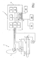
- This installation 2 shown diagrammatically, includes a tank 3 of liquid nitrogen and a freezing tunnel 4 in which move products 5 to be frozen on a strip 6 driven by a motor 7 in the direction of arrow 7A.
- the reservoir 3 is connected to the tunnel 4 by a conduit 8, the end of which opens into the tunnel carries a 8A liquid nitrogen vaporizer.
- a predefined quantity liquid nitrogen is injected into the tunnel 4 to freeze the products 5.
- the control device 1 comprises various means 9 to 13 for monitoring and controlling the operation of the refrigeration installation 2, namely a sensor 9 of the storage level of the liquid nitrogen contained in the tank 3, a sensor 10 of the nitrogen flow liquid feeding the tunnel 4, which is installed in the conduit 8, and two sensors 11 and 12 of the temperature prevailing in the tunnel 4 which are arranged respectively at the 8A vaporizer and at the outlet of the tunnel 4.
- a motor regulation unit 13 7 for change the tape speed of tape 6 and therefore the time products 5 in the tunnel 4.
- the sensor 9 is for example a pressure sensor differential, and the sensor 10 is a Vortex effect flow meter.
- the sensors 11 and 12 are for example platinum type temperature probes PT100.
- the signals supplied by means 9 to 13 can be of any suitable type.
- the sensors 9 and 10 are of the type to deliver a analog measurement signal of intensity between 4 and 20 mA while that the sensors 11 and 12 are of the type to deliver a measurement signal digital.
- the device 1 comprises a central unit 14 connected to each of the monitoring and control means 9 to 13 for collect, send and / or process information relating to the operation of installation 2.
- the unit 14 comprises means 15 for execution of configured tasks, and, connected to these, a means 16 for memorizing these configured tasks as well as a means of memorizing 17 tables of parameter values associated with the configured tasks.
- the means 15 furthermore have inputs / outputs which are connected to each of the means 9 to 13 for monitoring and control.
- the means 15 comprise for example a micro-controller or a microprocessor.
- the storage means 16 are either a disc hard, or a flash-EPROM type memory.
- the means 17 of memorization is for example a hard disk or a memory of the static RAM type.
- the parameter values are for example variable names, figures such as for example an alert threshold, arithmetic operators or any other information relating to a parameter of a parameterized task and necessary for its execution.
- the unit 14 comprises, connected to the means execution 15, a memory 18, for example of the RAM type, intended for the memorization of a parameterized task order according to which the tasks must be executed in closed loop and defining a general task continuous monitoring of the installation 2.
- the central unit 14 is further equipped with means 19 for communication linked to the means of execution and adapted to exchange information relating to the operation of installation 2, such as measured values or alarms, with different centers 20A and 20B of remote monitoring of the supplier, each specialized in one aspect of installation control 2.
- the 20A center is for example specialized in the temperature monitoring and control in tunnel 4 and / or the speed of the conveyor passing through it while the center 20B is specialized in monitoring the level of liquid nitrogen storage in the reservoir 3.
- the centers 20A and 20B are connected to the means of telecommunication 19 via the fixed or mobile telephone network.
- the means 19 are suitable for communicating with an interrogation station 20C the operating status of installation 2, which is located at the customer near installation 2 by standard wired or radio link 485.
- the telecommunication means 19 are for example communication ports in RS485 standard or MODEM in format PCMCIA or the like.
- control of the installation 2 can also be provided by a single remote monitoring center, but the specialization proves to be judicious for example in the case where the supplier puts at the different types of facilities available to its customers, many of which have a common module such as a nitrogen storage tank liquid.
- a single center be responsible for monitoring the levels of storage in the various reservoirs and replenishment thereof upon receipt of a replenishment order for all similar facilities in a given geographic area.
- the communication of the central unit 14 with these centers 20A and 20B of the supplier is carried out for example via a telephone network and that with extension 20C via a cable connection. Knowing that the networks are vulnerable from a communication breakdown point of view and also from a data transmission quality point of view, reduce the exchange of information with each center 20A and 20B to minimum.
- the communication means 19 are equipped means 21 for selecting the information to be sent to each center 20A, 20B.
- These means 21 comprise on the one hand means 22 for execution a mathematical algorithm for comparing information to be sent with the corresponding information that is available in each center 20A, 20B, and on the other hand means 23 for inhibiting a transmission of information controlled by said means 22.
- the mathematical comparison algorithm executed by the means 22 includes for example "proof by 9".
- the means 22 send to the means 23 a transmission inhibition signal information. Otherwise, the means 22 send to the means 23 a deactivation signal to allow the transmission of information.
- the central unit 14 is further equipped with means 24 for storage of information, such as a hard drive or RAM-type memory static.
- This information is in particular a history of information, recorded by means 9 to 13 of surveillance and / or communication in view the use of this data for, for example, forecast management of the installation.
- the information stored in the means 24 constitutes a database reflecting the state of installation 2, and can be interviewed by centers 20A and 20B. Via his post 20C, the client also has access to interrogate on the spot, at least partially, the information stored in the means 24.
- the unit 14 comprises means 25 for executing scheduled tasks.
- scheduled task is meant a task specific to installation 2 which cannot be configured because it relates for example to a particular processing of a measurement value.
- the means 25 are connected to the execution means 15 and to the means 17 of memorization of tables to for example dynamically change the value of a parameter in a table according to a scheduled task specific.
- Such a scheduled task concerns for example the conversion of a voltage value measured into a value of another quantity physics or the adjustment of a time interval between two instants of temperature measurement. It can also be the result of integration with respect to the time of a flow which is compensated by a multiplying factor dependent on temperature in order to obtain the volume of gas equivalent to a normalized temperature.
- the execution of a scheduled task is for example triggered by a configured task, following the detection of an event, at predetermined time intervals or even continuously.
- the means 25 for carrying out tasks programmed are further connected to the information storage means 24 to perform specific operations on the information stored in these means 24.
- the central unit 14 comprises for example a microcomputer equipped with one or more modems adapted to communicate with centers 20A and 20B via a telephone network and with extension 20C via a cable or radio link, and adapted interfaces for exchanging information with means 9 to 13.
- the microcomputer further comprises a memory for memorizing said tables and the configured tasks and a processor designed to perform tasks with suitable time sharing but also the scheduled tasks.
- control device 1 For means control, such as the unit 13 for regulating the drive motor 7, the device 1 operates in a corresponding manner.
- a parameterized task stored in the means 16 and to be performed by the means 15 relates to the acquisition, at predefined time intervals, measured values delivered by each sensors 9 to 12.
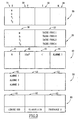
- the values of the parameters X, Y, Z and M are saved in the storage means 17 in the form of an associated table 30 to the aforementioned parametric task and represented in FIG. 2.
- Table 30 has four columns 31 to 34 or more in which respectively show the values of the parameters X, Y, Z and M as defined above about the task set "Acquisition of measured values". Each row of table 30 is associated with one of the sensors 9 to 12.
- the means 15 execute the task parameterized above by taking the values of parameters X, Y, Z and M of the table 30 of each line, from the first to the last.
- the advantage of such a parameterized task is that in the modification of the installation to be checked, for example the installation an additional sensor, the device 1 can be easily adapted.
- the means 15 execute the parameterized task "acquisition of measured values" of the first until the last row of table 30 and takes into account the parameter values of the new additional sensor.
- control device 1 easily adapts to any type of installation, because the measurement sensors and transducers control used to monitor and / or control the operation of a installation are generally of the type to deliver a voltage corresponding to the value of a physical quantity measured, or to receive a voltage or a current corresponding to a regulation command.
- the measurement sensors and transducers control used to monitor and / or control the operation of a installation are generally of the type to deliver a voltage corresponding to the value of a physical quantity measured, or to receive a voltage or a current corresponding to a regulation command.
- For each type of installation simply memorize the task configured "acquisition of measured values "in means 16 and to declare for each sensor the required values of the parameters defined in a table associated with this task configured and stored in the medium 17.
- the storage level N had been acquired in the form of a voltage delivered by the sensor 9 and stored in digital form at the memory location carrying the address 6 of the storage means 24.
- this voltage value is converted into "m 3 " by means of the programmed task "prog task. 1 ”which takes into account the calibration curve of sensor 9, and recorded in the memory location bearing address 6.
- Table 40 relates to a parameterized comparison task values converted during the execution of the configured task relating to table 35, to predefined thresholds for activation possible an alarm procedure.
- Table 40 has four columns 41 to 44 in which the parameter values appear respectively like the name of the measured variable, a predefined threshold, an operator comparison arithmetic and variable name of an alarm procedure which takes the value "1" if the alarm procedure in question must be activated, and "0" in the case of a negative comparison result.
- the first line of table 40 it is a comparison of the storage level N of the reservoir 3 with a predefined threshold equal to 10m 3 .
- the storage level N measured by the sensor 9 must be greater than 10m 3 . If it is less than or equal to 10m 3 , the variable named "alarm 1" takes the value "1" and a corresponding alarm procedure must be activated.
- Table 50 relates to alarm procedures "alarms 1 at 3 "to be activated depending on the comparison results obtained during the execution of the parameterized comparison task associated with the table 40.
- Table 50 has three columns 51, 52 and 53. In the first Column 51 shows the variable name of the alarm procedure and in the second 52 and third 53 columns are the names of the centers of remote monitoring which must be called in the event of activation of one of the "alarm 1 to 3".
- Table 50 has the particularity that during its execution, it calls up a parameterized "sub-task" for calling each 20A and 20B remote monitoring center whose values of parameters are defined in table 60.
- Table 60 has three columns 61, 62 and 63 in which the names of the call centers, telephone number and exchange protocol information.
- the links between the tables 30, 35, 40, 50 and 60 for monitoring the storage level N in the tank 3 are represented by arrows 70, 71, 72 and 73.
- alarm 1 In the case where the N value read and converted into "m 3 " by the sensor 9 is less than 10m 3 , alarm 1 must be activated, which consists of transmitting an alarm to the center 20B. The alarm is transmitted by calling the telephone number 0148 68 1278 using protocol 2.
- a continuous monitoring task is defined the installation by the order in which the configured tasks must be executed in closed loop, which is stored in memory 18.
- This order consists for example of first executing the associated parameterized task at table 30, then those associated with tables 35 and 40 and finally that associated with table 50 with the subtask associated with table 60.
- the means of execution 15 take into account each task configured one by one according to this predefined order, and each task is executed taking into account, line by line, the values of the parameters of the table associated with the task parameterized considered.
- Another parameterized task includes, for example, instructions for means 9 to 13 for monitoring and / or command for the regular storage of information revealed by the means 9 to 13 in the storage means 24 so as to constitute a information history.
- the information that is recorded in the means 24 can be interrogated remotely by one of the 20A centers, 20B from the supplier or by the customer by means of the interrogation station 20C.
- the means 21 for selection When transmitting data such as values measurement, towards one of the centers 20A, 20B, the means 21 for selection reduce the exchange of information to be sent in order to make the data transmission between the device 1 and each of the centers 20A, 20B More reliable.
- the means 22 apply the algorithm comparison mathematics both to the information to send and to corresponding information stored in centers 20A and 20 B. In depending on the result of the comparison, the means 22 send or not to the means 23 a signal to inhibit the transmission of information.
Landscapes
- Physics & Mathematics (AREA)
- General Physics & Mathematics (AREA)
- Engineering & Computer Science (AREA)
- Automation & Control Theory (AREA)
- Arrangements For Transmission Of Measured Signals (AREA)
- Testing And Monitoring For Control Systems (AREA)
- Control By Computers (AREA)
- Selective Calling Equipment (AREA)
Description
- au moins une valeur d'un paramètre d'une tâche paramétrée est un pointeur,
- il comprend, reliée aux moyens d'exécution des tâches, une mémoire d'un ordre selon lequel les tâches paramétrées doivent être exécutées en boucle fermée et définissant une tâche générale de contrôle,
- une tâche paramétrée comprend des requêtes de relevé d'informations par lesdits moyens de surveillance et/ou de commande du fonctionnement de ladite installation,
- une tâche paramétrée comprend des commandes destinées auxdits moyens de surveillance et/ou de commande,
- il comprend des moyens de stockage d'un historique d'informations relevées par les moyens de surveillance et/ou de commande, et au moins une tâche paramétrée comprend la mémorisation de ces informations dans les moyens de stockage,
- au moins une tâche paramétrée comprend l'activation d'une procédure d'alarme,
- il comprend des moyens de communication adaptés pour échanger des informations relatives au fonctionnement de l'installation avec au moins un centre de surveillance à distance de ladite installation et une tâche paramétrée comprend la transmission d'informations,
- la tâche paramétrée de transmission d'informations comprend la transmission d'au moins une alarme,
- les moyens de communication comprennent des moyens de sélection des informations à envoyer,
- lesdits moyens de sélection comprennent des moyens d'exécution d'un algorithme mathématique de comparaison des informations à envoyer avec les informations correspondantes qui sont disponibles dans le ou chaque centre de surveillance et des moyens d'inhibition d'une transmission d'informations commandés par lesdits moyens d'exécution de l'algorithme mathématique de comparaison,
- l'unité centrale comprend des moyens d'exécution de tâches programmées et au moins une tâche paramétrée fait appel à au moins une tâche programmée,
- les moyens d'exécution des tâches programmées sont reliés aux moyens de stockage d'informations pour exécuter des opérations sur les informations stockées dans ceux-ci,
- il comporte un micro-ordinateur comprenant une mémoire pour mémoriser lesdites tables et tâches paramétrées, et au moins une interface de couplage auxdits moyens de surveillance et/ou de commande du fonctionnement de ladite installation ainsi qu'une interface de communication avec le ou chaque centre de surveillance à distance, et dans lequel est chargé un programme adapté d'une part pour exécuter les tâches programmées et les tâches paramétrées en utilisant lesdites valeurs paramétrées mémorisées dans ladite ou lesdites tables, et d'autre part pour sélectionner les informations à envoyer.
- le paramètre X est le nom d'une variable, telle que N pour le niveau de stockage dans le réservoir 3 relevé par le capteur 9, D pour le débit d'azote liquide circulant dans le conduit 8, T1 pour la température mesurée par le capteur 11 et T2 pour la température mesurée par le capteur 12;
- le paramètre Y est l'adresse d'un des capteurs 9 à 12 et correspond à une entrée des moyens 15,
- le paramètre Z indique le type de signal à acquérir, par exemple analogique dans quel cas une conversion en une valeur numérique doit être effectuée par les moyens 15 au moyen d'un convertisseur analogique numérique intégré, ou numérique,
- le paramètre M correspond à une adresse d'un emplacement de mémoire des moyens 24 de stockage dans lequel la valeur saisie doit être enregistrée.
Claims (21)
- Dispositif (1) de contrôle d'une installation (2), comportant des moyens (9, 10, 11, 12, 13) de surveillance et/ou de commande du fonctionnement de ladite installation (2), et une unité centrale (14) de traitement d'informations, adapté pour communiquer avec lesdits moyens (9, 10, 11, 12, 13) de surveillance et/ou de commande pour relever, envoyer et/ou traiter des informations concernant le fonctionnement de l'installation (2), caractérisé en ce que l'unité centrale (14) comprend un moyen de mémorisation (16) d'au moins une tâche paramétrée agissant sur lesdites informations concernant le fonctionnement de l'installation (2), un moyen de mémorisation (17) d'au moins une table (30; 35, 40; 50; 60), chaque table (30; 35, 40; 50; 60) étant associée à une tâche paramétrée et comportant des valeurs des paramètres de la tâche considérée pour l'exécution de celle-ci, et, reliés à chaque moyen (16, 17) de mémorisation, des moyens (15) d'exécution desdites tâches paramétrées en utilisant lesdites valeurs mémorisées dans ladite ou lesdites tables lors de l'exécution desdites tâches paramétrées.
- Dispositif de contrôle selon la revendication 1, caractérisé en ce qu'au moins une valeur d'un paramètre d'une tâche paramétrée est un pointeur.
- Dispositif de contrôle selon la revendication 1 ou 2, caractérisé en ce qu'il comprend, reliée aux moyens (15) d'exécution des tâches, une mémoire (18) d'un ordre selon lequel les tâches paramétrées doivent être exécutées en boucle fermée et définissant une tâche générale de contrôle.
- Dispositif de contrôle selon l'une quelconque des revendications 1 à 3, caractérisé en ce qu'une tâche paramétrée comprend des requêtes de relevé d'informations par lesdits moyens (9, 10, 11, 12, 13) de surveillance et/ou de commande du fonctionnement de ladite installation (2).
- Dispositif de contrôle selon l'une quelconque des revendications 1 à 4, caractérisé en ce qu'une tâche paramétrée comprend des commandes destinées auxdits moyens (9, 10, 11, 12, 13) de surveillance et/ou de commande.
- Dispositif de contrôle selon l'une quelconque des revendications 1 à 5, caractérisé en ce qu'il comprend des moyens (24) de stockage d'un historique d'informations relevées par les moyens (9, 10, 11, 12, 13) de surveillance et/ou de commande, et en ce qu'au moins une tâche paramétrée comprend la mémorisation de ces informations dans les moyens de stockage.
- Dispositif de contrôle selon l'une quelconque des revendications 1 à 6, caractérisé en ce qu'au moins une tâche paramétrée comprend l'activation d'une procédure d'alarme.
- Dispositif de contrôle selon l'une quelconque des revendications 1 à 7, caractérisé en ce qu'il comprend des moyens (19) de communication adaptés pour échanger des informations relatives au fonctionnement de l'installation avec au moins un centre (20A, 20B) de surveillance à distance de ladite installation (2) et en ce qu'une tâche paramétrée comprend la transmission d'informations.
- Dispositif de contrôle selon la revendication 8, caractérisé en ce que la tâche paramétrée de transmission d'informations comprend la transmission d'au moins une alarme.
- Dispositif de contrôle selon la revendication 8 ou 9, caractérisé en ce que les moyens de communication (19) comprennent des moyens (21) de sélection des informations à envoyer.
- Dispositif de contrôle selon la revendication 10, caractérisé en ce que lesdits moyens (21) de sélection comprennent des moyens (22) d'exécution d'un algorithme mathématique de comparaison des informations à envoyer avec les informations correspondantes qui sont disponibles dans le ou chaque centre de surveillance (20A, 20B) et des moyens (23) d'inhibition d'une transmission d'informations commandés par lesdits moyens (22) d'exécution de l'algorithme mathématique de comparaison.
- Dispositif de contrôle selon l'une quelconque des revendications 1 à 11, caractérisé en ce que l'unité centrale (14) comprend des moyens (25) d'exécution de tâches programmées et en ce qu'au moins une tâche paramétrée fait appel à au moins une tâche programmée.
- Dispositif de contrôle selon la revendication 13, caractérisé en ce que les moyens (25) d'exécution des tâches programmées sont reliés aux moyens (24) de stockage d'informations pour exécuter des opérations sur les informations stockées dans ceux-ci.
- Dispositif de contrôle selon la revendication 12 ou 13, caractérisé en qu'il comporte un micro-ordinateur comprenant une mémoire pour mémoriser lesdites tables (30; 35, 40; 50; 60) et tâches paramétrées, et au moins une interface de couplage auxdits moyens de surveillance et/ou de commande du fonctionnement de ladite installation (2) ainsi qu'une interface de communication avec le ou chaque centre (20A, 20B) de surveillance à distance, et dans lequel est chargé un programme adapté d'une part pour exécuter les tâches programmées et les tâches paramétrées en utilisant lesdites valeurs paramétrées mémorisées dans ladite ou lesdites tables, et d'autre part pour sélectionner les informations à envoyer.
- Procédé de contrôle d'une installation (2), utilisant des moyens (9, 10, 11, 12, 13) de surveillance et/ou de commande du fonctionnement de ladite installation (2), et une unité centrale (14) de traitement d'informations, adapté pour communiquer avec lesdits moyens (9, 10, 11, 12, 13) de surveillance et/ou de commande pour relever, envoyer et/ou traiter des informations concernant le fonctionnement de l'installation (2), caractérisé en ce qu'il comporte les étapes de :mémoriser, dans l'unité centrale (14), au moins une tâche paramétrée agissant sur lesdites informations concernant le fonctionnement de l'installation (2),mémoriser dans l'unité centrale (14) au moins une table (30; 35, 40; 50; 60), chaque table (30; 35, 40; 50; 60) étant associée à une tâche paramétrée et comportant des valeurs des paramètres de la tâche considérée pour l'exécution de celle-ci, et,exécuter lesdites tâches paramétrées en utilisant lesdites valeurs mémorisées dans ladite ou lesdites tables lors de l'exécution desdites tâches paramétrées.
- Procédé de contrôle selon la revendication 15, caractérisé en ce qu'au moins une valeur d'un paramètre d'une tâche paramétrée est un pointeur.
- Procédé de contrôle selon la revendication 15 ou 16, caractérisé en ce qu'une tâche paramétrée comprend des requêtes de relevé d'informations par lesdits moyens (9, 10, 11, 12, 13) de surveillance et/ou de commande du fonctionnement de ladite installation (2).
- Procédé de contrôle selon l'une quelconque des revendications 15 à 17, caractérisé en ce qu'une tâche paramétrée comprend des commandes destinées auxdits moyens (9, 10, 11, 12, 13) de surveillance et/ou de commande.
- Procédé de contrôle selon l'une quelconque des revendications 15 à 18, caractérisé en ce qu'il comprend une étape de stockage d'un historique d'informations relevées par les moyens (9, 10, 11, 12, 13) de surveillance et/ou de commande, et en ce qu'au moins une tâche paramétrée comprend la mémorisation de ces informations.
- Procédé de contrôle selon l'une quelconque des revendications 15 à 19, caractérisé en ce qu'au moins une tâche paramétrée comprend l'activation d'une procédure d'alarme.
- Procédé de contrôle selon l'une quelconque des revendications 15 à 20, caractérisé en ce que l'unité centrale (14) exécute des tâches programmées et en ce qu'au moins une tâche paramétrée fait appel à au moins une tâche programmée.
Applications Claiming Priority (3)
| Application Number | Priority Date | Filing Date | Title |
|---|---|---|---|
| FR9708030 | 1997-06-26 | ||
| FR9708030A FR2765365B1 (fr) | 1997-06-26 | 1997-06-26 | Dispositif de controle d'une installation |
| PCT/FR1998/001373 WO1999000715A1 (fr) | 1997-06-26 | 1998-06-26 | Dispositif de controle d'une installation |
Publications (2)
| Publication Number | Publication Date |
|---|---|
| EP0991987A1 EP0991987A1 (fr) | 2000-04-12 |
| EP0991987B1 true EP0991987B1 (fr) | 2003-09-17 |
Family
ID=9508491
Family Applications (1)
| Application Number | Title | Priority Date | Filing Date |
|---|---|---|---|
| EP98933743A Revoked EP0991987B1 (fr) | 1997-06-26 | 1998-06-26 | Dispositif de controle d'une installation |
Country Status (13)
| Country | Link |
|---|---|
| US (1) | US6321130B1 (fr) |
| EP (1) | EP0991987B1 (fr) |
| JP (1) | JP2002508097A (fr) |
| CN (1) | CN1265201A (fr) |
| AR (1) | AR016096A1 (fr) |
| AT (1) | ATE250238T1 (fr) |
| AU (1) | AU744732B2 (fr) |
| BR (1) | BR9810474A (fr) |
| CA (1) | CA2294263A1 (fr) |
| DE (1) | DE69818262D1 (fr) |
| FR (1) | FR2765365B1 (fr) |
| TW (1) | TW416536U (fr) |
| WO (1) | WO1999000715A1 (fr) |
Families Citing this family (6)
| Publication number | Priority date | Publication date | Assignee | Title |
|---|---|---|---|---|
| RU2160919C1 (ru) * | 2000-05-10 | 2000-12-20 | Бурба Александр Алексеевич | Устройство для контроля параметров |
| CA2822893C (fr) | 2010-12-29 | 2019-03-05 | Dow Agrosciences Llc | Systemes et procedes contre les derives de pulverisation, comprenant un dispositif d'entree |
| HUE034531T2 (en) | 2010-12-29 | 2018-02-28 | Dow Agrosciences Llc | Permeability Control System and Procedure |
| DE102014010189B4 (de) * | 2014-07-10 | 2019-03-28 | Diehl Metering Gmbh | Zählervorrichtung mit Rechenwerk und Volumengeber, Modul und Verfahren zum Betrieb einer Zählervorrichtung |
| DE102015225617A1 (de) * | 2015-02-06 | 2016-08-11 | Robert Bosch Gmbh | Verfahren zur Überwachung eines Drive-by-Wire-Systems eines Kraftfahrzeugs |
| NL2035025B1 (en) * | 2023-06-07 | 2024-12-19 | Exel Ind | Spray nozzle for an agricultural device, spraying system with said nozzle, an agricultural device with said nozzle and a method for dispensing a liquid |
Family Cites Families (13)
| Publication number | Priority date | Publication date | Assignee | Title |
|---|---|---|---|---|
| JPS5874847A (ja) * | 1981-10-30 | 1983-05-06 | Hitachi Ltd | 電子式エンジン制御装置 |
| US4654806A (en) * | 1984-03-30 | 1987-03-31 | Westinghouse Electric Corp. | Method and apparatus for monitoring transformers |
| FR2642547B1 (fr) * | 1989-01-09 | 1991-05-17 | Aerospatiale | Systeme modulaire de surveillance d'installations industrielles |
| SE463338B (sv) * | 1989-06-14 | 1990-11-05 | Ludwik Liszka | Saett att oevervaka och/eller diagnosticera aktuella drifttillstaand hos komplicerade maskiner |
| GB2247757B (en) * | 1990-09-06 | 1994-05-04 | Delco Electronics Corp | Electronic controller for vehicle |
| DE4325860A1 (de) * | 1992-08-01 | 1994-02-03 | Siemens Ag | Verfahren und leittechnisches System zum Steuern, Überwachen und Regeln insbesondere von komplexen industriellen Prozessen, wie z. B. in einem Kernkraftwerk |
| JPH06203040A (ja) * | 1992-12-28 | 1994-07-22 | Honda Motor Co Ltd | 製造経歴管理システム |
| SG42898A1 (en) * | 1993-01-11 | 1997-10-17 | Hitachi Ltd | Production control system |
| US5659781A (en) * | 1994-06-29 | 1997-08-19 | Larson; Noble G. | Bidirectional systolic ring network |
| US5602757A (en) * | 1994-10-20 | 1997-02-11 | Ingersoll-Rand Company | Vibration monitoring system |
| IT1275465B (it) * | 1995-07-03 | 1997-08-07 | Tiziano Barea | Dispositivo di controllo dell'alimentazione di una pluralita' di fili o filati ad una macchina tessile avente mezzi sensori codificati e metodo per il suo controllo |
| DE69529907T2 (de) * | 1995-11-17 | 2003-12-18 | Tornos S.A., Moutier | Verfahren und Programm einer numerischen Steuerung einer Werkzeugmaschine und numerische Steuerung, die mit Mitteln dieses Programms arbeitet |
| US5892690A (en) * | 1997-03-10 | 1999-04-06 | Purechoice, Inc. | Environment monitoring system |
-
1997
- 1997-06-26 FR FR9708030A patent/FR2765365B1/fr not_active Expired - Fee Related
-
1998
- 1998-06-26 BR BR9810474-8A patent/BR9810474A/pt not_active IP Right Cessation
- 1998-06-26 JP JP50534699A patent/JP2002508097A/ja active Pending
- 1998-06-26 US US09/105,198 patent/US6321130B1/en not_active Expired - Fee Related
- 1998-06-26 TW TW087215997U patent/TW416536U/zh not_active IP Right Cessation
- 1998-06-26 AT AT98933743T patent/ATE250238T1/de not_active IP Right Cessation
- 1998-06-26 CN CN98807495A patent/CN1265201A/zh active Pending
- 1998-06-26 WO PCT/FR1998/001373 patent/WO1999000715A1/fr not_active Ceased
- 1998-06-26 CA CA002294263A patent/CA2294263A1/fr not_active Abandoned
- 1998-06-26 EP EP98933743A patent/EP0991987B1/fr not_active Revoked
- 1998-06-26 AR ARP980103083A patent/AR016096A1/es active IP Right Grant
- 1998-06-26 AU AU83456/98A patent/AU744732B2/en not_active Ceased
- 1998-06-26 DE DE69818262T patent/DE69818262D1/de not_active Expired - Lifetime
Also Published As
| Publication number | Publication date |
|---|---|
| TW416536U (en) | 2000-12-21 |
| AR016096A1 (es) | 2001-06-20 |
| CN1265201A (zh) | 2000-08-30 |
| FR2765365A1 (fr) | 1998-12-31 |
| JP2002508097A (ja) | 2002-03-12 |
| EP0991987A1 (fr) | 2000-04-12 |
| AU8345698A (en) | 1999-01-19 |
| ATE250238T1 (de) | 2003-10-15 |
| DE69818262D1 (de) | 2003-10-23 |
| FR2765365B1 (fr) | 1999-08-06 |
| WO1999000715A1 (fr) | 1999-01-07 |
| BR9810474A (pt) | 2000-09-19 |
| US6321130B1 (en) | 2001-11-20 |
| CA2294263A1 (fr) | 1999-01-07 |
| AU744732B2 (en) | 2002-02-28 |
Similar Documents
| Publication | Publication Date | Title |
|---|---|---|
| EP0650169B1 (fr) | Système de surveillance d'une installation industrielle | |
| EP0129482B1 (fr) | Installation modulaire pour l'assemblage et/ou l'usinage de pièces, avec dispositifs claviers-afficheurs à chaque poste | |
| EP0905498B1 (fr) | Procédé de génération d'au moins un signal d'alerte relatif au niveau dans un réservoir de stockage d'un produit et dispositif pour la mise en oeuvre du procédé | |
| FR2828945A1 (fr) | Systeme et procede multi-niveaux de maintenance predictive et de diagnostic a distance extensible a un tres grand nombre de machines | |
| FR2481833A1 (fr) | Appareil de compilation et de controle de donnees pendant l'essai d'un puits souterrain | |
| EP0991987B1 (fr) | Dispositif de controle d'une installation | |
| CA2114634A1 (fr) | Procede de diagnostic d'un processus evolutif | |
| EP0534876A1 (fr) | Procédé et installation de remplissage de bouteilles de gaz liquide et de contrôle desdites bouteilles après remplissage | |
| FR2544518A1 (fr) | Appareil electronique de commande pour installation de propulsion | |
| EP0903264B1 (fr) | Système d'affichage d'informations pour véhicule automobile | |
| FR2722597A1 (fr) | Dispositif de controle des parametres d'un processus de fabrication | |
| EP0076766B1 (fr) | Perfectionnements aux dispositifs de contrôle de niveau de liquide contenu dans un réservoir | |
| EP0926429A1 (fr) | Dispositif de distribution d'un gaz de travail et installation de fourniture d'un gaz de travail equipée d'un tel dispositif | |
| FR2565714A1 (fr) | Procede et systeme de surveillance et de gestion a distance exploites et consultes par terminal videotex | |
| EP0661673A1 (fr) | Procédé de gestion de la maintenance d'un véhicule, ordinateur de bord et station de diagnostic associée mettant en oeuvre le procédé | |
| EP0432033B1 (fr) | Procédé de mise en oeuvre d'une ronde de surveillance d'installations nucléaires | |
| EP1390819A1 (fr) | Systeme de diagnostic predictif dans un automate programmable | |
| CA2294628A1 (fr) | Installation de surveillance a distance d'un parc d'appareils heterogenes de production industrielle | |
| EP0181259A1 (fr) | Procédé et dispositif de mesure de consommation relative d'énergie de chauffage des logements d'un immeuble collectif | |
| FR2630384A1 (fr) | Procede d'automatisation de la commande de stations de lavage rapide a libre service pour vehicules automobiles | |
| EP1388830B1 (fr) | Système et procédé de gestion à distance d'équipements | |
| LU87244A1 (fr) | Procede d'automatisation de la commande de stations de lavage rapide a libre service pour vehicules automobiles | |
| FR2795164A1 (fr) | Systeme pour l'exploitation et la gestion d'un parc de conteneurs refrigeres | |
| WO2002086777A1 (fr) | Dispositif de controle et de gestion de l'approvisionnement et de la distribution de carburants dans les stations-service | |
| EP0847954A1 (fr) | Système de surveillance du fonctionnement d'au moins un ascenseur |
Legal Events
| Date | Code | Title | Description |
|---|---|---|---|
| PUAI | Public reference made under article 153(3) epc to a published international application that has entered the european phase |
Free format text: ORIGINAL CODE: 0009012 |
|
| 17P | Request for examination filed |
Effective date: 19991231 |
|
| AK | Designated contracting states |
Kind code of ref document: A1 Designated state(s): AT BE CH CY DE DK ES FI FR GB GR IE IT LI LU MC NL PT SE |
|
| RAP1 | Party data changed (applicant data changed or rights of an application transferred) |
Owner name: L'AIR LIQUIDE, S.A. A DIRECTOIRE ET CONSEIL DE SUR |
|
| GRAH | Despatch of communication of intention to grant a patent |
Free format text: ORIGINAL CODE: EPIDOS IGRA |
|
| GRAH | Despatch of communication of intention to grant a patent |
Free format text: ORIGINAL CODE: EPIDOS IGRA |
|
| GRAA | (expected) grant |
Free format text: ORIGINAL CODE: 0009210 |
|
| AK | Designated contracting states |
Kind code of ref document: B1 Designated state(s): AT BE CH CY DE DK ES FI FR GB GR IE IT LI LU MC NL PT SE |
|
| PG25 | Lapsed in a contracting state [announced via postgrant information from national office to epo] |
Ref country code: NL Free format text: LAPSE BECAUSE OF FAILURE TO SUBMIT A TRANSLATION OF THE DESCRIPTION OR TO PAY THE FEE WITHIN THE PRESCRIBED TIME-LIMIT Effective date: 20030917 Ref country code: LI Free format text: LAPSE BECAUSE OF NON-PAYMENT OF DUE FEES Effective date: 20030917 Ref country code: IT Free format text: LAPSE BECAUSE OF FAILURE TO SUBMIT A TRANSLATION OF THE DESCRIPTION OR TO PAY THE FEE WITHIN THE PRESCRIBED TIME-LIMIT;WARNING: LAPSES OF ITALIAN PATENTS WITH EFFECTIVE DATE BEFORE 2007 MAY HAVE OCCURRED AT ANY TIME BEFORE 2007. THE CORRECT EFFECTIVE DATE MAY BE DIFFERENT FROM THE ONE RECORDED. Effective date: 20030917 Ref country code: IE Free format text: LAPSE BECAUSE OF FAILURE TO SUBMIT A TRANSLATION OF THE DESCRIPTION OR TO PAY THE FEE WITHIN THE PRESCRIBED TIME-LIMIT Effective date: 20030917 Ref country code: GB Free format text: LAPSE BECAUSE OF FAILURE TO SUBMIT A TRANSLATION OF THE DESCRIPTION OR TO PAY THE FEE WITHIN THE PRESCRIBED TIME-LIMIT Effective date: 20030917 Ref country code: FI Free format text: LAPSE BECAUSE OF FAILURE TO SUBMIT A TRANSLATION OF THE DESCRIPTION OR TO PAY THE FEE WITHIN THE PRESCRIBED TIME-LIMIT Effective date: 20030917 Ref country code: CY Free format text: LAPSE BECAUSE OF FAILURE TO SUBMIT A TRANSLATION OF THE DESCRIPTION OR TO PAY THE FEE WITHIN THE PRESCRIBED TIME-LIMIT Effective date: 20030917 Ref country code: CH Free format text: LAPSE BECAUSE OF NON-PAYMENT OF DUE FEES Effective date: 20030917 Ref country code: AT Free format text: LAPSE BECAUSE OF FAILURE TO SUBMIT A TRANSLATION OF THE DESCRIPTION OR TO PAY THE FEE WITHIN THE PRESCRIBED TIME-LIMIT Effective date: 20030917 |
|
| REG | Reference to a national code |
Ref country code: GB Ref legal event code: FG4D Free format text: NOT ENGLISH |
|
| REG | Reference to a national code |
Ref country code: CH Ref legal event code: EP |
|
| REF | Corresponds to: |
Ref document number: 69818262 Country of ref document: DE Date of ref document: 20031023 Kind code of ref document: P |
|
| REG | Reference to a national code |
Ref country code: IE Ref legal event code: FG4D Free format text: FRENCH |
|
| PG25 | Lapsed in a contracting state [announced via postgrant information from national office to epo] |
Ref country code: SE Free format text: LAPSE BECAUSE OF FAILURE TO SUBMIT A TRANSLATION OF THE DESCRIPTION OR TO PAY THE FEE WITHIN THE PRESCRIBED TIME-LIMIT Effective date: 20031217 Ref country code: GR Free format text: LAPSE BECAUSE OF FAILURE TO SUBMIT A TRANSLATION OF THE DESCRIPTION OR TO PAY THE FEE WITHIN THE PRESCRIBED TIME-LIMIT Effective date: 20031217 Ref country code: DK Free format text: LAPSE BECAUSE OF FAILURE TO SUBMIT A TRANSLATION OF THE DESCRIPTION OR TO PAY THE FEE WITHIN THE PRESCRIBED TIME-LIMIT Effective date: 20031217 |
|
| PG25 | Lapsed in a contracting state [announced via postgrant information from national office to epo] |
Ref country code: DE Free format text: LAPSE BECAUSE OF FAILURE TO SUBMIT A TRANSLATION OF THE DESCRIPTION OR TO PAY THE FEE WITHIN THE PRESCRIBED TIME-LIMIT Effective date: 20031218 |
|
| PG25 | Lapsed in a contracting state [announced via postgrant information from national office to epo] |
Ref country code: PT Free format text: LAPSE BECAUSE OF FAILURE TO SUBMIT A TRANSLATION OF THE DESCRIPTION OR TO PAY THE FEE WITHIN THE PRESCRIBED TIME-LIMIT Effective date: 20031226 |
|
| PG25 | Lapsed in a contracting state [announced via postgrant information from national office to epo] |
Ref country code: ES Free format text: LAPSE BECAUSE OF FAILURE TO SUBMIT A TRANSLATION OF THE DESCRIPTION OR TO PAY THE FEE WITHIN THE PRESCRIBED TIME-LIMIT Effective date: 20031228 |
|
| NLV1 | Nl: lapsed or annulled due to failure to fulfill the requirements of art. 29p and 29m of the patents act | ||
| GBV | Gb: ep patent (uk) treated as always having been void in accordance with gb section 77(7)/1977 [no translation filed] |
Effective date: 20030917 |
|
| REG | Reference to a national code |
Ref country code: IE Ref legal event code: FD4D |
|
| PLBI | Opposition filed |
Free format text: ORIGINAL CODE: 0009260 |
|
| PLBQ | Unpublished change to opponent data |
Free format text: ORIGINAL CODE: EPIDOS OPPO |
|
| PG25 | Lapsed in a contracting state [announced via postgrant information from national office to epo] |
Ref country code: MC Free format text: LAPSE BECAUSE OF NON-PAYMENT OF DUE FEES Effective date: 20040630 |
|
| PLAX | Notice of opposition and request to file observation + time limit sent |
Free format text: ORIGINAL CODE: EPIDOSNOBS2 |
|
| 26 | Opposition filed |
Opponent name: LINDE AKTIENGESELLSCHAFT Effective date: 20040601 |
|
| PLAX | Notice of opposition and request to file observation + time limit sent |
Free format text: ORIGINAL CODE: EPIDOSNOBS2 |
|
| PLBB | Reply of patent proprietor to notice(s) of opposition received |
Free format text: ORIGINAL CODE: EPIDOSNOBS3 |
|
| PGFP | Annual fee paid to national office [announced via postgrant information from national office to epo] |
Ref country code: CH Payment date: 20050519 Year of fee payment: 8 |
|
| PGFP | Annual fee paid to national office [announced via postgrant information from national office to epo] |
Ref country code: LU Payment date: 20050601 Year of fee payment: 8 |
|
| PGFP | Annual fee paid to national office [announced via postgrant information from national office to epo] |
Ref country code: BE Payment date: 20050606 Year of fee payment: 8 |
|
| PGFP | Annual fee paid to national office [announced via postgrant information from national office to epo] |
Ref country code: FR Payment date: 20060511 Year of fee payment: 9 |
|
| RDAF | Communication despatched that patent is revoked |
Free format text: ORIGINAL CODE: EPIDOSNREV1 |
|
| REG | Reference to a national code |
Ref country code: CH Ref legal event code: PL |
|
| RDAG | Patent revoked |
Free format text: ORIGINAL CODE: 0009271 |
|
| STAA | Information on the status of an ep patent application or granted ep patent |
Free format text: STATUS: PATENT REVOKED |
|
| 27W | Patent revoked |
Effective date: 20061023 |