EP0992143B1 - Intelligentes nachrichtensystem - Google Patents
Intelligentes nachrichtensystem Download PDFInfo
- Publication number
- EP0992143B1 EP0992143B1 EP98930014A EP98930014A EP0992143B1 EP 0992143 B1 EP0992143 B1 EP 0992143B1 EP 98930014 A EP98930014 A EP 98930014A EP 98930014 A EP98930014 A EP 98930014A EP 0992143 B1 EP0992143 B1 EP 0992143B1
- Authority
- EP
- European Patent Office
- Prior art keywords
- data
- interchange
- message
- electronic data
- electronic
- Prior art date
- Legal status (The legal status is an assumption and is not a legal conclusion. Google has not performed a legal analysis and makes no representation as to the accuracy of the status listed.)
- Expired - Lifetime
Links
Images










Classifications
-
- G—PHYSICS
- G06—COMPUTING OR CALCULATING; COUNTING
- G06Q—INFORMATION AND COMMUNICATION TECHNOLOGY [ICT] SPECIALLY ADAPTED FOR ADMINISTRATIVE, COMMERCIAL, FINANCIAL, MANAGERIAL OR SUPERVISORY PURPOSES; SYSTEMS OR METHODS SPECIALLY ADAPTED FOR ADMINISTRATIVE, COMMERCIAL, FINANCIAL, MANAGERIAL OR SUPERVISORY PURPOSES, NOT OTHERWISE PROVIDED FOR
- G06Q10/00—Administration; Management
- G06Q10/10—Office automation; Time management
Definitions
- the present invention refers to systems and methods for electronic data interchange messaging, i.e. for the interchange of electronic messages comprising and transferring data provided in a predefined, preferably standardized structure or form in such a way that said data may be identified and used as data element values or strings in further processing functions by the receiving system or application.
- EDIFACT Electronic Data Interchange For Administration, Commerce and Transport
- EDIFACT is well established in Europe, and electronic data interchange system, EDIFACT provides a set of rules for, for example, the syntax and message meaning/sentence to be used within the EDIFACT system.
- X.12 is a similar standardized system used in the USA.
- An object of the invention is to increase the speed and simplicity of the design, construction, implementation, management, maintenance and use of electronic data interchange systems and processes.
- a computer software application preferably comprises: a data definition defining the information that has to be successively stored and recalled by the application, said data definition being used for data mapping in relation to incoming/outgoing messages; a process describing the expected sequence of messages, event rules to be applied on the message data for detection of certain conditions, timers supervising deadlines of certain events or updates, and events to be issued due to timer expiring or other conditions; data mapping from message data to application data (IMA data); and data mapping from application data (IMA data) to event data when issuing an event.
- terms such as electronic data interchange, electronic data interchange message, and the like refer to electronic messages comprising and transferring data provided in a predefined, preferably standardized structure or form in such a way that said data may be identified and used as data element values or strings in further processing functions by the receiving system or application.
- process execution is in the context of the present invention referring to the execution of a process from its initial start all the way to its end. That is, the executional steps made by a process after an event causes the process to resume execution, or before an event causes the process to make a temporary halt in the execution, are not considered as a process execution, but merely as a part thereof.
- a regular email text body does not constitute an electronic data interchange message according to the invention unless the body comprises data arranged in a predefined structure so that the receiving system or application may derive or extract said data therefrom. Note however that this does not mean that the sending/receiving of such unstructured text bodies may not be included in a process according to the invention, as an addition to the sending/receiving of true electronic data interchange messages.
- a computer application provides an electronic data interchange process working in intimate interaction with a data instance of a data definition associated with the specific process.
- the data definition for the process is defined in advance and is set to include primarily such data that are needed in downstream steps in the process.
- a process as a whole may deal with an amount of incoming or outgoing data, either in relation to electronic data interchange messages or in relation to a relational database, such as a SQL (Standard Query Language) database, or other formats, as well as processing data derived and/or used in the process itself.
- a relational database such as a SQL (Standard Query Language) database, or other formats, as well as processing data derived and/or used in the process itself.
- SQL Standard Query Language
- the use of a SQL relational database requires the execution of a series of requests or query steps for retrieving of the desired information.
- such data is preferably stored in a process specific, sequential and collected data instance of a process data definition, preferably stored in a sequential file system, preferably using predefined indices, so as to be easy and fast retrievable for the process execution.
- a data definition including a set of data elements to be provided with data needed for expedient execution of the entire process, is defined in advance in relation to the definition of the process.
- a new data instance of the data definition is created for each execution of the process.
- all or part of the information successively provided in the data instance may be e.g. stored in a relational database at the end of the process, thereby reducing need for real-time process-database-interaction.
- data received in for example a transportation order message is consecutively stored in one or more tables in a database, each table comprising a list of rows corresponding to all received transportation orders.
- Data provided in a later received delivery confirmation for example, is consecutively stored in one or more rows relating to one or more tables in the database, each table comprising a list of rows corresponding to all received delivery confirmations.
- non of said tables provides information as to the overall processed case, merely to one part of the overall process case.
- the use of a relational database for storage requires requesting and data mapping programs intermediate the process and the database.
- the data instance As the data instance, preferably stored in a sequential file system, will be successively provided with electronic data interchange messaging data as the process proceeds, the data instance may be said to represent the entire process in a time flow perspective.
- the invention solves the problem of how to store and look up data that are related to a series of predefined activities in a specific process case. The invention hence provides a better control of the process time perspective.
- an electronic data interchange process of the kind mentioned above is constructed using a limited set of function blocks of the kind disclosed herein.
- said function blocks may be visualized on a computer monitor in the form of symbols, each symbol being associated with a respective function block.
- Two or more function blocks forming an entire process or part thereof can preferably be grouped to a composite function block being more complex than the original function blocks.
- a user accomplishes this through the user interface by grouping at least two existing symbols, each symbol being associated with a respective function block, to a new symbol definition to be stored preferably together with the existing symbol definition resources of the system.
- the user also has the possibility to add one or more data definitions comprising one or more set of data elements to the new symbol definition. In this way the solution to a complex problem, and the design thereof, can be stored in a repository for future distribution or modification in connection with designing an electronic data interchange messaging process.
- one advantage of the invention is that it provides simplified transformation of a process design into a technical implementation, whereas prior art techniques make this transformation very difficult.
- Another advantage of the invention is that it saves time and costs with respect to the process design, the technical implementation, as well as the maintenance and processing of the system. The invention also makes it easier to connect process design activities and process implementation activities.
- a synchronizing function comprising: to define an expected number of events; to count the number of occurred events; and to end said function as soon as one of the following two conditions are fulfilled: a) said number of occurred events is equal to said expected number of events; b) a synchronizing timer is expired.
- the synchronizing function preferably includes one or several of the following function blocks: a waiting block executing the function of stopping the process in awaiting whichever comes first: the occurrence of a predefined number of expected events or the expiring of a timer; a message sending block executing the function of sending an electronic data interchange message and setting a timer to be used in a following synchronizing block, said message comprising information stored in at least one data element of a data instance of said data definition.
- Other preferred function blocks include: a starting block performing the function of awaiting the receiving of an electronic data interchange message and storing data included in said message in at least one designated data element of a data instance of said data definition; and a starting block performing the function of allocating a data instance of the data definition for the execution of the process.
- Fig. 1 shows an emblem of an Intelligent Messaging Application, IMA, according to the present invention.
- the application may be viewed as an underlying messaging process, involving electronic data interchange, associated with an IMA process data instance following the process.
- the intelligent messaging application is a special type of application that helps synchronize EDI message activities (messages to/from applications and to/from persons) into one manageable process. Most of the activities in the intelligent messaging application are automated processing of information, although the processing in single cases may involve manual interaction.
- an intelligent messaging application comprising an electronic data interchange process, hence includes one or more electronic data interchange message dialogs between different computer systems or applications.
- Fig. 2 shows an emblem of an Intelligent Messaging Application data instance (IMA data instance) according to the invention.
- the data instance is a collection of data which is related to a specific case in a process, such as a business process, a transportation process or a technical process.
- the data instance may include a collection of all data that is related to, and essential for, the control and attest of an invoice, the control of a work flow of a production factory or machine, or the like, such control involving electronic data interchange.
- the data instance may include the invoice data, the order data related to the invoice, payment authorization data, signature data and notes data made by the person attesting the invoice.
- the data instance will follow a flow, or process, in an intelligent messaging application.
- the application is preferably designed so as to be able to handle several data instances at the same time.
- An IMA data instance is preferably created based upon an underlying data definition every time an electronic data interchange message or another type of event, such as the expiring of a timer, the receiving of a clock signal or the changing of a monitored state starts an electronic data interchange process.
- the process work flow will dynamically change depending on decisions taken in the process.
- the data in the data instance will change accordingly for every IMA data instance.
- the application can add, change and remove information to/from the data instance.
- every data instance is given a unique reference number.
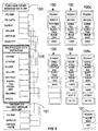
- FIG. 3 shows an example of the relationship between data received or transmitted in electronic data interchange messages in a process, data mapping, a data definition for the process and data instances of the data definition according to the invention.
- an IMA process data definition 105 relates to a predefined electronic data interchange process (not shown), in this case a purchase transaction process.
- the application is to receive a purchase order from a buyer in the form of an electronic data interchange message.
- This message will contain purchase order data in a predefined structure according to a purchase order message data definition 100.
- purchase data will be provided in a structured, predefined manner in the purchase message, thus enabling the application to derive the purchase data from the message.
- the purchase order message data definition 100 will include, according to the predefined structure, a purchase order reference (PO ref), a purchase order date (PO date) a designated buyer (Buyer) (in this case the sender of the message), a designated seller (Seller) (in this case the receiver of the message), an ordered article (Article) and a quantity (Quantity) thereof.
- PO ref purchase order reference
- PO date purchase order date
- Buyer, Seller, Article and Quantity data of the purchase order data definition need to be stored in a data instance 105a, 105b, 105c of the IMA process data definition 105, each data instance 105a, 105b, 105c corresponding to a respective execution of the process.
- these five entities are to be mapped into a data instance of the IMA process data definition 105, as is indicate by the box connecting lines in Fig. 3.
- the application is to send an Uncomplete Delivery message to the buyer, also in the form of an electronic data interchange message, in case the seller cannot deliver the ordered quantity at the delivery date.
- this Uncomplete Delivery data will also be provided in a structured, predefined manner in the Uncomplete Delivery message based upon a predefined Uncomplete Delivery message data definition 101.
- the Uncomplete Delivery message data definition includes the purchase order reference (PO ref), the ordered article that was uncomplete (Article) and a calculated difference (Difference).
- an automated function block will decide how many articles that actually can be delivered and then update the IMA data instance with such data, i.e. the promised number of articles (Promised), the promised delivery date (Delivery), and the agreed prize (Prize).
- the data to be contained in the Uncomplete Delivery message may be derived and mapped from the data instance of the IMA data definition 105 into the EDI message, in this case using process logic to calculate said difference.
- the entire process and the related IMA process data definition 105 When constructing the entire process and the related IMA process data definition 105, the entire process for example comprising further steps than the one described above, it has been decided in the example shown in Fig. 3. that the IMA process data definition shall contain the entities PO ref, Status, Buyer, Seller, Article, Expected, Promised, Delivery and Price. Hence, the IMA process data definition preferably defines such information that has to be recalled by the application in later steps in the process.
- Fig. 3 there are shown three examples of executions of the process.
- a purchase order 100a has been received by the application, designating the ordering of 3000 15w light bulbs.
- the data instance 105a of the IMA process data definition 105 shows the situation when merely having received this purchase order message. Hence, it can be seen that no promised delivery has been made and the status of the IMA data instance is "Ordered" (IMA process not complete).
- a purchase order 100b has been received by the application, designation the ordering of 10000 40w light bulbs.
- the IMA data instance 105b of the IMA process data definition 105 shows the situation when having accepted this order. Since in this case it has been decided in the process that the delivery can be made at a given date, the order has been accepted without the need to send any Uncomplete Delivery message. Hence, it can be seen that a promise of a delivery of 10000 units on January 13. 1997 at the prize of $1.79 has been made and that the status of the data instance is "Accepted" (IMA process complete).
- a purchase order 100c has been received by the application, designation the ordering of 2000 60w light bulbs.
- the IMA data instance 105c of the IMA process data definition 105 shows the situation when having accepted this order. Since in this case it has been decided in the process that a complete delivery cannot be made at the moment, the order has been accepted with a reservation in the form of an Uncomplete Delivery message 101c. Hence, it can be seen that a promise of delivery of 1200 units on February 1. 1997 at the prize of $1.79 has been made, resulting in an Uncomplete Delivery Message designating the difference of 800 60w light bulbs, and that the status of the data instance is "Accepted" (IMA process complete).
- each execution of the process i.e. each purchase transaction, is associated with a respective data instance of the IMA process data definition.
- each IMA data instance is successively provided with information preferably to be used in later processing steps, wherein data in some data elements of the data instance may change during the process.
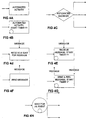
- Fig. 4a-4h shows different function objects, symbols or blocks to be used in an electronic data interchange process according to the invention.
- the set of function blocks shown in Fig. 4a-4h has been found to be very advantageous when used to form complete electronic data interchange processes. Hence intelligent messaging applications and processes are preferably developed and constructed using the function blocks described below.
- the function blocks in Fig. 4a-4h have generic functionality and becomes specialized when put into a specific process or application.
- Fig. 4a shows an automated activity function block.
- An automated activity function block performs at least one predefined function in relation to the IMA data instance associated with the present execution of the process.
- the predefined function may for example include the performing of an automated logical operation on the IMA data instance, for example using of some type of programming code (C, C++, Java), the addressing of another routine, the creation of the IMA data instance, or the like.
- Fig. 4b shows an automated activity, start timer function block.
- An automated activity, start timer function block performs at least one predefined function in relation to the IMA data instance associated with the present execution of the process, as is discussed above with reference to Fig. 4a, and starts a timer (timer yl in Fig. 4b).
- the automated activity, start timer function may for example: create the IMA data instance if the automated activity, start timer function is placed first in the process; declare an event and start a timer telling that within a certain time frame a specific event is supposed to happen (which will be discussed further with reference to Fig. 4h below).
- Fig. 4c shows an automated decision function block.
- An automated decision function block will dynamically change the flow of the data instance through the process. The change of the flow is based upon a predefined rule, for example the flow will change in relation to the outcome of an automated logical or arithmetic operation on the IMA data instance.
- the rule is setup in the automated decision function block and preferably uses data in the IMA data instance associated with the present execution of the process. Even though three outcomes or outgoing process paths from the automated decision function block are shown in Fig 4c, the true number of outcomes or outgoing process paths is arbitrary and may be set in dependence of desired process. Each outgoing process path will lead to the issuing of new events.
- Fig. 4d shows a receive and wait for message function block.
- a receive and wait for message function block will wait for an electronic data interchange message and, when this is received, load the IMA data instance associated with the present execution of the process with data received in the message.
- a receive and wait for message function block is often preferably placed first in an electronic data interchange process according to the invention. If placed first in the process, the receive and wait for message function block preferably also creates the IMA data instance associated with the present execution of the process.
- Fig. 4e shows a receive message, start timer function block.
- a receive message, start timer function block will start a timer set to a predefined time frame (timer yl in Fig. 4e) and will expect to receive an electronic data interchange message within the given time frame.
- the receive message, start timer function block declares the expected receiving of an EDI message and starts a timer telling that within the given time frame the message is supposed to be received. If the message is not received within the given time frame, an exemption event will be generated, as will be discussed further with reference to Fig. 4h below.
- the receive message, start timer function block, as well as the other blocks disclosed herein, will also provide the required mapping rules for transferring message data from the message to the IMA data instance.
- Fig. 4f shows a send message function block.
- a send message function block will send an electronic data interchange message and preferably use data stored of the IMA data instance associated with the present execution of the process to create the message to be sent. Hence, as discussed above, the function block will provide the required mapping rules for transferring message data from the IMA data instance to the message.
- Fig. 4g shows a send and receive message, start timer function block.
- a send and receive message, start timer function block will perform exactly the same functions as the send message block (Fig. 4f) and the receive message, start timer function block (Fig. 4e) put together.
- the send and receive message, start timer function block will send an electronic data interchange message, start a timer set to a predefined time frame (timer yl in Fig. 4g), and expect to receive an answer in the form of an electronic data interchange message within the given time frame.
- the send and receive message, start timer function block sends an EDI message, declares the expected receiving of an EDI message answer, and starts a timer telling that within the given time frame the answer is supposed to be received. If the answer is not received within the given time frame, an exemption event will be generated, as will be discussed further with reference to Fig. 4h below.
- function blocks discussed in relation to Fig. 4d, 4e, 4f and 4g may also be used to provide information read from a database, received via email, inputted/sent via a user interface, or inputted/sent via Java, C++, C or other programming language, to/from the data instance, i.e. not exclusively using EDI messages in the truest sense.
- Fig. 4h shows a wait for (n) event function block according to the invention.
- the wait for (n) event function block will stop the process and wait for the occurrence of a predefined expected number of events or the expiring of a predefined timer setup in one or more of the above mentioned function blocks.
- start timer function block (Fig. 4b); or the receiving of one or more messages that was earlier setup/declared in a receive message, start timer function block (Fig. 4e) or a send and receive message, start timer function block (Fig. 4g).
- the process will continue as soon as the timer designated in the wait for (n) event function block expires or the number of expected events designated in the wait for (n) event function block has occurred.
- this function block there are two possible outcomes of this function block: all expected events occur within the time frame given by the designated timer, and the process consequently continues before the expiring of the timer; or fewer events than the expected number of events occur within the time frame given by the designated timer, and the process continues as the timer expires despite the fact that not all expected events has occurred.
- One specific possibility of the latter outcome is that no event occur within the time frame given by the designated timer and the process continues as the timer expires despite the fact that no event has occurred.
- the timer-expired-outcome may be designed as one single flow path or several flow paths, since this outcome may in some cases accommodate several different possibilities.
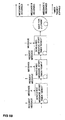
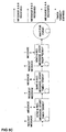
- Fig. 5a, 5b and 5c show three different examples of process management of multiple answers.
- start timer function blocks are used to request three answers to be received as message A, message B and message C, respectively, and to start a timer "Demol"
- the wait for (n) event function block is set to wait for all three events, i.e. the receiving of all three messages, in consideration of the timer "Demo1".
- the process will follow two different paths, a first path if all three messages are received before the timer expires and a second path if the timer expires before all three messages have been received.
- the second path hence accommodates three possibilities: the timer expires after the receiving of two messages; the timer expires after the receiving of one message; or the timer expires before the receiving of any message, even though these three possibilities have been illustrated as one single outcome.
- the wait for (n) event function block is set to wait for only one event of the three events, i.e. the receiving of only one message, in consideration of the timer "Demol".
- the process will follow four different paths: a first path if message A is received first and before the expiring of the timer; a second path if message B is received first and before the expiring of the timer; a third path if message C is received first and before the expiring of the timer; and a fourth path if no message is received before the expiring of the timer.
- the wait for (n) event function block is set to wait for only two event of the three events, i.e. the receiving of only two message, in consideration of the timer "Demol".
- the process will follow four different paths: a first path if messages A and B are received first and before the expiring of the timer; a second path if messages B and C are received first and before the expiring of the timer; a third path if messages C and A are received first as and before the expiring of the timer; and a fourth path if no message or only one message is received before the expiring of the timer.
- the wait for (n) event function block makes it possible to managed multiple events in many different ways, creating different types of process paths and configurations.
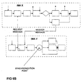
- Fig. 6a and 6b shows two different ways of providing synchronization and management of parallel electronic data interchange processes according to the invention.
- a first electronic data interchange process IMAx starts two parallel electronic data interchange processes, IMAy and IMAz, by sending two starting messages thereto.
- the processes IMAy and IMAz are preferably started by or synchronized with the first process IMAz using a receive message block such as the one shown in Fig. 4d, 4e or 4g.
- a send and receive message, start timer function block is used in a second process IMAy, together with a wait for one event function block, to synchronize the second process IMAy to a first process IMAx.
- the wait for (n) event function block is of great benefit when synchronizing or controlling the process flow, this block is also referred to as a synchronizing block.
- an electronic data interchange process according to the invention may be divided into two or more sub processes, and two or more processes may be put together to form an overall process.
- an IMA data instance may be divided into two or more sub data instances, and two or more IMA data instances may be put together to form an overall IMA data instance, all depending on the actual application and situation.
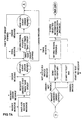
- an "Invoice Control" process is started by the receiving of an invoice message in a first block, this causing the creation of an IMA data instance for the present execution of the invoice control process, the IMA data instance for example being provided with relevant invoice data.
- the order message relating to the present invoice message is requested from the order application to be received within a time frame set by a timer "Wait Order". If no order is received within the given time, person 1 is informed in a next block and the order waiting step is repeated.
- the process continues to an automated decision block, wherein it is decided, based upon process rules, whether or not the content of the invoice corresponds to the order. If so, an "Attest" process is started by the sending of a start attest message. However, if the content of the order does not match the invoice, an "invoice not accepted” message is sent to the supplier and person 2 is informed via email. In both cases, the created data instance is stored before the process is ended. In most of the blocks shown in Fig. 7a, the process makes use of the IMA data instance, either by writing data into the IMA data instance, as in the first and last blocks, or by reading data from the IMA data instance, as in the block deciding if the invoice content is equal to the order content.
- FIG. 7b Another example of an electronic data interchange process will now be described with reference to Fig. 7b.
- Fig. 7b an "Attest" process is started by the receiving of the start attest message shown in Fig. 7a.
- a new IMA data instance is created in the first block in Fig. 7b, preferably using invoice information provided in the start attest message.
- the process in Fig. 7b continues to an automated decision block, wherein it is decided whether or not the invoice amounts to more or less than $1000. If the invoice refers to less than $1000, no attest is required, while relying on the already performed invoice control, and the process continues directly to a pay message block. However, if the invoice refers to more than $1000, the process goes to a block which sends an email to person 3, requesting an attest within a certain time frame.
- the process goes to a similar block which sends an email to person 4, requesting the attest message.
- the process continues to the above mentioned pay message block, wherein a message is sent to the account system to pay the invoice.
- an accept message is requested within a given time frame, and this accept message is monitored until received.
- information from the data instance is stored.
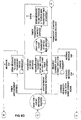
- Fig. 8 shows the invoice control process of Fig. 7a when described using SDL (Specification and Description Language) symbols and language.
- SDL is an international standard issued by ITU-T (former CCITT), containing instructions for storing and defining the behavior of a system with parallel activities. Since the invoice attest process already has been described above with reference to Fig. 7a, and since the symbols used in Fig. 8 are well known to one skilled in the art, further description thereof will be omitted. However, it is well understood that the initial three steps S11, S12 and S13 in Fig.
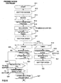
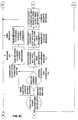
- FIG. 19a shows an overview of the main partners involved (Supplier, Receiver and Carrier) and which EDI messages that are exchanged (204, 214, 856, 990). It is clear that the exemplified procedure shown in Fig. 9b-9e is executed at the Supplier. The process will handle all electronic data interchange messaging to/from the external partners.
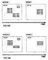
- Fig. 10a shows two EDI messages which for example could be the messages received by the invoice control process previously described with reference to Fig. 7a, hence they have been named Invoice 1 and Order 1, respectively.
- the invoice message for example received by the first block in Fig. 7a, causing the creation of an IMA data instance denoted A for the flow of the invoice control process, contains the invoice data elements A1...D1 with invoice data.
- the order message for example received either by the second or the fourth block in Fig. 7a, contains the order data elements E1...G1 with order data.
- Fig. 10a shows two EDI messages which for example could be the messages received by the invoice control process previously described with reference to Fig. 7a, hence they have been named Invoice 1 and Order 1, respectively.
- the invoice message for example received by the first block in Fig. 7a, causing the creation of an IMA data instance denoted A for the flow of the invoice control process, contains the invoice data elements A1...D1 with invoice data.
- the order message for example
- the created IMA data instance A is stored using only one single table, i.e. all the data elements are stored sequentially in one time sequential table.
- the invoice data elements A1...D1 from the invoice message are stored, and after reception of the order message these elements are followed by the order data elements E1...G1.
- an IMA process can handle several IMA data instances at the same time it may receive a second invoice message followed by a second order message while the IMA data instance A is still being handled by the process flow.
- These latter received messages shown in Fig. 10b and denoted Invoice 2 and Order 2, respectively, result in the creation of an IMA data instance B.
- the IMA data instance B is stored in another table in the same sequential way as the IMA data instance A but in a table separated from the table of IMA data instance A.
- Fig. 11 also shows the time sequential table for IMA data instance B, and the time axis further indicates that the creation of the data instance B occurs later than the creation of the data instance A, but that the storage of data elements partly takes place at the same time for the two data instances.
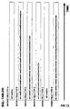
- Fig. 12 shows the tables of an SQL database, which is another way to organize and store data.
- the data is sorted in tables according to the type of the fields or data elements in a message.
- the field A1 from message Invoice 1 and the field A2 from message Invoice 2 are stored in one table.
- the fields B1 from Invoice 1 and the fields B2 from Invoice 2 are stored in another table with the keys to the right Invoice A1 or A2 and so on.
- Fig. 11 and Fig. 12 shows two different schemes of how to organize and store the EDI message data.
- each IMA data instance is stored in only one sequential IMA data instance table
- an SQL database in accordance with Fig. 12 the collection of data in each message is stored in several SQL tables.
- SQL tables When comparing these schemes it is easily understood that the utilization of SQL tables requires more computer resources since the data is split into several tables. Assume, for example, that the process from Fig. 7a wishes to compare the invoice fields B1 with the order fields G1.
- IMA data instance tables only one single table, including both B1 and G1, needs to be located and locked by a transaction function, the latter in order to keep the data in the table consistent.
- this particular example requires that two tables, one including B1 and one including G1, are located and locked by means of SQL transaction functions. This difference becomes even more apparent when there are a lot more messages and IMA data instances to handle and store than just the ones in the example above.
- Fig. 13 shows a computer system according to an embodiment of the present invention.
- the computer system comprises a computer 1 including: processing means 2, in the form of a CPU, for executing an electronic data interchange process 3 (in Fig. 13, one process has been indicated, however, as is understood, several different processes may be executed by the processing means) and for reading data from, and writing data into, data elements of a data instance during process execution; storing means 4, in the form of a memory, with a sequential memory file for storing data instances of different data definitions belonging to different processes (in Fig. 13, a data instance 5 corresponding to the process 3 has been indicated); communication means 6, in the form of a port on an interface circuit, for receiving and sending 7 electronic data interchange messages 8 from/to a receiver; and a relational database 9 for storing a data instance at the end of a process.
- the system also comprises terminals or computers 10 utilized by the staff for interacting with the electronic data interchange processes.
- Fig. 13 data instance 5 based upon an underlying data definition is created and stored in a sequential memory file 4 when an electronic data interchange message 8 or another type of event initially starts a process 3 corresponding to the data definition.
- Data included in an electronic data interchange message 8 received by the port 6 is written by the process 3 into the data elements of the data instance 5 corresponding to said process 3, and data to be included in an electronic data interchange message 8 to be sent from the port 6 is read by the process 3 from the data elements of the corresponding data instance 5.
- information can be added, changed and removed to/from the data instance 5 in the sequential memory file 4, and at the. end of the process information in the data instance may be stored in a relational database 9.
- a staff member may, for example, give the process 3 commands or data, or he/she may receive information, for example, in the form of an e-mail sent from the process 3 to the terminal or computer 10.
- Fig. 14 shows an embodiment of a system for designing an electronic data interchange messaging process. Elements already described with reference to Fig. 13 are denoted with the same numerals, and further description thereof is omitted for ease of description. Hence, in addition to what has been described with reference to Fig. 13, the system in Fig.
- display means 10 in the form of a computer screen, for displaying symbols 11, representing electronic data interchange process blocks;.interface means 12, in the form of a keyboard and a mouse, for a user to design a sequence of symbols by associating said symbols to each other in a desired sequence 13 on said screen 10; and interpretation and data definition defining means 14, in the form of an interpreter realized as an executable software module, for interpreting said sequence 13 of symbols and, based thereupon, defining an electronic data interchange process 3 based upon the electronic data interchange process blocks represented by said associated symbols.
- the symbols 11 displayed on the screen 10 represent, and are associated with, all the respective function blocks that an electronic data interchange process can include, such as: the automated activity function block; the automated activity, start timer function block; the automated decision function block; the receive and wait for message function block; the receive message, start timer function block; the send message function block; the send and receive message, start timer function block; the wait for (n) event function block, and different complex composite function blocks, as described above with reference to Fig. 4a-4h.
- a user selects symbols representing those function blocks that are needed to design a process of a certain desired behaviour. Via the keyboard and/or the mouse 12 the user may also define one or more data definitions that should be related to the designed process.
- the selected symbols are associated with each other in certain desired sequence 13 making up a part of a, or a complete, process. Since each symbol is associated with a particular function block, the sequence of symbols, together with the possibly defined data definitions, is interpreted by the interpreter 14 in order to define an electronic data interchange process based on the function blocks and their relative positions in accordance with the sequence of symbols.
- the interpreter 14 defines the data definitions based on what a user may input with the keyboard and/or mouse regarding the desired type of data to be associated with the electronic data interchange process.
- the electronic data interchange process is either immediately upon creation or afterwards transferred to the computer system 1.
- An article of manufacture 15 in the form of a computer readable disc may store any software means needed for a system or a computer to be able to; display symbols; design a sequence of symbols; interpret a sequence of symbols; define an electronic data interchange process from a set of symbols; and to execute an electronic data interchange process. All these means stored on the disc is then made available to the system or the computer by loading the software stored on the disc.
Landscapes
- Engineering & Computer Science (AREA)
- Business, Economics & Management (AREA)
- Strategic Management (AREA)
- Entrepreneurship & Innovation (AREA)
- Human Resources & Organizations (AREA)
- Operations Research (AREA)
- Economics (AREA)
- Marketing (AREA)
- Data Mining & Analysis (AREA)
- Quality & Reliability (AREA)
- Tourism & Hospitality (AREA)
- Physics & Mathematics (AREA)
- General Business, Economics & Management (AREA)
- General Physics & Mathematics (AREA)
- Theoretical Computer Science (AREA)
- Information Transfer Between Computers (AREA)
- Multi Processors (AREA)
Claims (27)
- Verfahren für elektronische Datenaustausch-Mitteilungsübertragung, bei dem ein elektronischer Datenaustauschprozess (3) im Zusammenhang mit elektronischen Daten ausgeführt wird, die bei der Ausführung des Prozesses nacheinander zu übertragen oder zu verarbeiten sind, dadurch gekennzeichnet, dass die elektronischen Daten in einer prozessspezifischen Dateninstanz (5) einer vorgegebenen Datendefinition gespeichert sind, wobei die Datendefinition einen Satz von Datenelementen für elektronische Daten definiert, die von dem Prozess nacheinander zu speichern und abzurufen sind, und wobei der Prozess während der Ausführung des Prozesses automatisch in einer empfangenen elektronischen Datenaustausch-Mitteilung (8) enthaltene Daten in vorgegebene Datenelemente der Dateninstanz der Datendefinition schreibt und Daten für den elektronischen Datenaustausch daraus liest, und wobei der elektronische Datenaustauschprozess einen Satz vorgegebener Funktionsblöcke umfasst, wobei die Blöcke einen Warteblock enthalten, der die Funktion ausführt, abzuwarten, welches der folgenden Ereignisse zuerst eintritt: das Auftreten einer vorgegebenen Anzahl erwarteter Ereignisse oder das Ablaufen eines Zeitgebers.
- Verfahren nach Anspruch 1, wobei jede Ausführung des Prozesses mit einer entsprechenden Dateninstanz der Datendefinition verbunden ist.
- Verfahren nach Anspruch 1 oder 2, das das sequentielle Speichern der Datenelemente der Dateninstanz in einer sequentiellen Speicherdatei (4) während des Prozesses umfasst.
- Verfahren nach Anspruch 1, 2 oder 3, das das Speichern eines Teilsatzes der in der Dateninstanz enthaltenen Daten am Ende des Prozesses umfasst.
- Verfahren nach Anspruch 1,2, 3 oder 4, wobei die Ereignisse das Empfangen einer elektronischen Datenaustausch-Mitteilung umfassen.
- Elektronisches Datenaustausch-Mitteilungsübertragungssystem, das umfasst:dadurch gekennzeichnet, dass das System enthält:eine Verarbeitungseinrichtung (2), die einen elektronischen Datenaustauschprozess (3) ausführt, wobei bei jeder Ausführung des Prozesses elektronische Daten übertragen oder verarbeitet werden; undeine Einrichtung (6), die elektronische Datenaustausch-Mitteilungen (8) empfängt und sendet;wobei die Verarbeitungseinrichtung einen Zeitgeber enthält und den Prozess ausführt, indem sie einen Satz vorgegebener Funktionsblöcke ausführt, wobei die Blöcke einen Warteblock enthalten, der die Funktion ausführt, abzuwarten, welches der folgenden Ereignisse zuerst eintritt: das Auftreten einer vorgegebenen Anzahl erwarteter Ereignisse oder das Ablaufen des Zeitgebers.eine Speichereinrichtung (4), die eine prozessspezifische Dateninstanz (5) einer vorgegebenen Datendefinition speichert, die einen vorgegebenen Satz von Datenelementen für elektronische Daten enthält, die von dem Prozess (3) nacheinander zu speichern und abzurufen sind; undeine Einrichtung (2), die während der Ausführung des Prozesses (3) automatisch in einer empfangenen elektronischen Datenaustausch-Mitteilung enthaltene Daten in die entsprechenden Datenelemente der Dateninstanz (5) schreibt und Daten für das Senden elektronischer Datenaustausch-Mitteilungen daraus liest,
- System nach Anspruch 6, wobei jede Ausführung des Prozesses mit einer entsprechenden Dateninstanz der Datendefinition verbunden ist.
- System nach Anspruch 6 oder 7, das eine sequentielle Speicherdatei (4) zum sequentiellen Speichern der Datenelemente der Dateninstanz während des Prozesses umfasst.
- System nach Anspruch 6, 7 oder 8, das eine Einrichtung (9) umfasst, die am Ende des Prozesses einen Teilsatz der in der Dateninstanz enthaltenden Daten speichert.
- System nach einem der Ansprüche 6 - 9, wobei die Verarbeitungseinrichtung mit der Ausführung des Prozesses beginnt, wenn sie eine vorgegebene elektronische Datenaustausch-Mitteilung empfängt.
- System nach einem der Ansprüche 6 - 9, wobei die Verarbeitungseinrichtung mit der Ausführung des Prozesses beim Ablaufen eines Zeitgebers oder bei der Veränderung eines Zustandes beginnt, der von der Verarbeitungseinrichtung überwacht wird.
- System nach einem der Ansprüche 6 - 11, wobei die Ereignisse das Empfangen einer elektronischen Datenaustausch-Mitteilung umfassen.
- System zum Entwickeln eines elektronischen Datenaustausch-Mlttellungsübertragungsprozesses, das umfasst:eine Anzeigeeinrichtung (10), die Symbole (11) anzeigt, die elektronische Datenaustausch-Prozessblöcke darstellen;eine Schnittstelleneinrichtung (12) für einen Benutzer zum Entwickeln einer Sequenz (13) von Symbolen durch Zuordnen der Symbole zueinander in einer gewünschten Sequenz auf der Anzeigeeinrichtung;eine Interpretationseinrichtung (14), die die Sequenz von Symbolen interpretiert und auf dieser Grundlage einen elektronischen Datenaustauschprozess (3) definiert, der auf den elektronischen Datenaustausch-Prozessblöcken basiert, die durch die zugeordneten Symbole dargestellt werden; undeine Datendefinitionseinrichtung (14), die eine Datendefinition in Bezug auf den entwickelten elektronischen Datenaustauschprozess (3) definiert, wobei die Datendefinition einen Satz Datenelemente umfasst, die bei jeder Ausführung des Prozesses auszutauschen sind, und die Datendefinitionseinrichtung die Datendefinition automatisch auf der Grundlage vorgegebener eingegebener und ausgegebener elektronischer Datenaustausch-Mitteilungsdaten des Prozesses definiert.
- System nach Anspruch 13, wobei die Schnittstelleneinrichtung den Benutzer in die Lage versetzt, die Datendefinition zu definieren.
- System nach Anspruch 13 oder 14, die eine Verarbeitungseinrichtung (2) umfasst, die den elektronischen Datenaustauschprozess (3) ausführt.
- System nach Anspruch 15, wobei jede Ausführung des Datenaustauschprozesses mit einer Dateninstanz (5) einer Datendefinition für den Prozess verbunden ist.
- System nach Anspruch 16, das eine sequentielle Speicherdatei (4) zum sequentiellen Speichern der Datenelemente der Dateninstanz während des Prozesses umfasst.
- System nach einem der Ansprüche 13 - 17, wobei der entwickelte Prozess während der Ausführung des Prozesses automatisch in einer elektronischen Datenaustausch-Mitteilung enthaltene Daten in die entsprechenden Datenelemente einer Dateninstanz der Datendefinition schreibt und Daten für den elektronischen Datenaustausch daraus liest.
- System nach einem der Ansprüche 13 -18, wobei die Symbole ein Symbol umfassen, das einem Warteblock entspricht, der die Funktion ausführt, abzuwarten, welches der folgenden Ereignisse zuerst eintritt: das Auftreten einer vorgegebenen Anzahl erwarteter Ereignisse oder das Ablaufen eines Zeitgebers.
- System nach einem der Ansprüche 14 - 19, das eine Speichereinrichtung (9) umfasst, die am Ende des Prozesses einen Teilsatz der in der Dateninstanz enthaltenen Daten speichert.
- Herstellungsgegenstand (15), der eine Einrichtung umfasst, die einen Computer veranlasst:auf einer Anzeigeeinrichtung (10) Symbole (11) anzuzeigen, die elektronische Datenaustausch-Prozessblöcke darstellen;einem Benutzer eine Einrichtung (12) zum Entwickeln einer Sequenz (13) von Symbolen durch Zuordnung der Symbole auf der Anzeigeeinrichtung zueinander zur Verfügung zu stellendie von dem Benutzer entwickelte Sequenz von Symbolen zu interpretieren und auf dieser Grundlage einen elektronischen Datenaustauschprozess (3) zu definieren, der auf den elektronischen Datenaustauschblöcken basiert, die durch die zugeordneten Symbole dargestellt werden; undeine Datendefinition in Bezug auf den entwickelten elektronischen Datenaustauschprozess zu definieren, die einen Satz von Datenelementen umfasst, die von definierten Datenelementtypen sind und bei jeder Ausführung des Prozesses auszutauschen sind.
- Herstellungsgegenstand nach Anspruch 21, der eine Einrichtung umfasst, die einen Computer veranlasst, den elektronischen Datenaustauschprozess auszuführen.
- Herstellungsgegenstand nach Anspruch 22, der eine Einrichtung umfasst, die den Computer veranlasst, eine Dateninstanz (5) der Datendefinition für jede Ausführung des Prozesses zuzuweisen.
- Herstellungsgegenstand nach einem der Ansprüche 21 - 23, der eine Einrichtung umfasst, die den Computer veranlasst, die Ausführung des Prozesses durch den Empfang einer vorgegebenen elektronischen Datenaustausch-Mitteilung auszulösen.
- Herstellungsgegenstand nach einem der Ansprüche 21- 24, wobei der entwickelte Prozess bei der Ausführung des Prozesses automatisch elektronische Mitteilungsdaten (8) in die entsprechenden Datenelemente einer Dateninstanz der Datendefinition schreibt und elektronische Mitteilungsdaten daraus liest.
- Herstellungsgegenstand nach einem der Ansprüche 21 - 25, der eine Einrichtung umfasst, die den Computer veranlasst, am Ende der Ausführung des Prozesses einen Teilsatz der in der Dateninstanz der Datendefinition enthaltenen Daten zu speichern.
- Herstellungsgegenstand nach einem der Ansprüche 21 - 26, wobei der Herstellungsgegenstand die Form eines computerlesbaren Speichers hat.
Applications Claiming Priority (5)
| Application Number | Priority Date | Filing Date | Title |
|---|---|---|---|
| SE9702432 | 1997-06-25 | ||
| SE9702432A SE9702432L (sv) | 1997-06-25 | 1997-06-25 | Elektroniska meddelanden |
| US940024 | 1997-09-29 | ||
| US08/940,024 US6256667B1 (en) | 1997-09-29 | 1997-09-29 | Intelligent messaging |
| PCT/SE1998/001197 WO1998059480A1 (en) | 1997-06-25 | 1998-06-18 | Intelligent messaging |
Publications (2)
| Publication Number | Publication Date |
|---|---|
| EP0992143A1 EP0992143A1 (de) | 2000-04-12 |
| EP0992143B1 true EP0992143B1 (de) | 2001-12-12 |
Family
ID=26663019
Family Applications (1)
| Application Number | Title | Priority Date | Filing Date |
|---|---|---|---|
| EP98930014A Expired - Lifetime EP0992143B1 (de) | 1997-06-25 | 1998-06-18 | Intelligentes nachrichtensystem |
Country Status (6)
| Country | Link |
|---|---|
| EP (1) | EP0992143B1 (de) |
| JP (1) | JP2001508905A (de) |
| AU (1) | AU727293B2 (de) |
| DE (1) | DE69802932D1 (de) |
| IL (1) | IL133664A0 (de) |
| WO (1) | WO1998059480A1 (de) |
Families Citing this family (3)
| Publication number | Priority date | Publication date | Assignee | Title |
|---|---|---|---|---|
| GB2369973B (en) | 2000-12-06 | 2002-12-04 | Open Business Exchange Ltd | Communication Router |
| KR100830725B1 (ko) | 2004-01-07 | 2008-05-20 | 노키아 코포레이션 | 인증 방법 |
| GB0400270D0 (en) | 2004-01-07 | 2004-02-11 | Nokia Corp | A method of authorisation |
-
1998
- 1998-06-18 IL IL13366498A patent/IL133664A0/xx unknown
- 1998-06-18 WO PCT/SE1998/001197 patent/WO1998059480A1/en not_active Ceased
- 1998-06-18 EP EP98930014A patent/EP0992143B1/de not_active Expired - Lifetime
- 1998-06-18 AU AU79496/98A patent/AU727293B2/en not_active Ceased
- 1998-06-18 DE DE69802932T patent/DE69802932D1/de not_active Expired - Lifetime
- 1998-06-18 JP JP50430999A patent/JP2001508905A/ja active Pending
Also Published As
| Publication number | Publication date |
|---|---|
| AU7949698A (en) | 1999-01-04 |
| EP0992143A1 (de) | 2000-04-12 |
| DE69802932D1 (de) | 2002-01-24 |
| JP2001508905A (ja) | 2001-07-03 |
| AU727293B2 (en) | 2000-12-07 |
| WO1998059480A1 (en) | 1998-12-30 |
| IL133664A0 (en) | 2001-04-30 |
| HK1027460A1 (en) | 2001-01-12 |
Similar Documents
| Publication | Publication Date | Title |
|---|---|---|
| US6256667B1 (en) | Intelligent messaging | |
| EP0788631B1 (de) | Verteiltes arbeitsfluss-management | |
| US7788319B2 (en) | Business process management for a message-based exchange infrastructure | |
| AU2001249273B2 (en) | Method and system for top-down business process definition and execution | |
| van der Aalst et al. | Beyond workflow management: product-driven case handling | |
| RU2400814C2 (ru) | Иерархические проекты в системе и способе управления проектом, обеспечиваемые компьютером | |
| JP4429908B2 (ja) | セントラルマスタデータ管理 | |
| US8526316B2 (en) | System and method for dynamically modifying synchronized business information server interfaces | |
| CN1601541B (zh) | 用于自维护的实时数据聚集的方法和数据处理装置 | |
| US7836103B2 (en) | Exchanging project-related data between software applications | |
| US8443036B2 (en) | Exchanging project-related data in a client-server architecture | |
| US20020065701A1 (en) | System and method for automating a process of business decision and workflow | |
| US20060212543A1 (en) | Modular applications for mobile data system | |
| AU2001249273A1 (en) | Method and system for top-down business process definition and execution | |
| CA2332401A1 (en) | Work-flow system for web-based applications | |
| EP0992143B1 (de) | Intelligentes nachrichtensystem | |
| US20030177279A1 (en) | Creation of middleware adapters from paradigms | |
| EP1246054A1 (de) | Erstellen von Software-Programmen aus Software-Komponenten | |
| HK1027460B (en) | Intelligent messaging | |
| US20040122749A1 (en) | System and method for managing manufacturing orders | |
| Yoo | An industrial application of agents for dynamic planning and scheduling | |
| AU2021101551A4 (en) | System and Method for Context-Aware Computing | |
| Bosworth | Data Routing Rather than Databases: The Meaning of the Next Wave of the Web Revolution to Data Management. | |
| JP2025109369A (ja) | 情報処理システム、情報処理装置、サーバ装置、プログラム、クラウド、又は方法 | |
| JP2002189842A (ja) | ワークフロー管理制御システムとその方法並びにワークフロー管理制御プログラムを記録した記録媒体 |
Legal Events
| Date | Code | Title | Description |
|---|---|---|---|
| PUAI | Public reference made under article 153(3) epc to a published international application that has entered the european phase |
Free format text: ORIGINAL CODE: 0009012 |
|
| 17P | Request for examination filed |
Effective date: 20000118 |
|
| AK | Designated contracting states |
Kind code of ref document: A1 Designated state(s): BE DE FR GB NL SE |
|
| GRAG | Despatch of communication of intention to grant |
Free format text: ORIGINAL CODE: EPIDOS AGRA |
|
| 17Q | First examination report despatched |
Effective date: 20010212 |
|
| GRAG | Despatch of communication of intention to grant |
Free format text: ORIGINAL CODE: EPIDOS AGRA |
|
| GRAH | Despatch of communication of intention to grant a patent |
Free format text: ORIGINAL CODE: EPIDOS IGRA |
|
| GRAH | Despatch of communication of intention to grant a patent |
Free format text: ORIGINAL CODE: EPIDOS IGRA |
|
| GRAA | (expected) grant |
Free format text: ORIGINAL CODE: 0009210 |
|
| RIN1 | Information on inventor provided before grant (corrected) |
Inventor name: NILSSON, MIKAEL Inventor name: SKOG, ANDERS Inventor name: WAHLANDER, CHRISTER |
|
| AK | Designated contracting states |
Kind code of ref document: B1 Designated state(s): BE DE FR GB NL SE |
|
| PG25 | Lapsed in a contracting state [announced via postgrant information from national office to epo] |
Ref country code: NL Free format text: LAPSE BECAUSE OF FAILURE TO SUBMIT A TRANSLATION OF THE DESCRIPTION OR TO PAY THE FEE WITHIN THE PRESCRIBED TIME-LIMIT Effective date: 20011212 Ref country code: FR Free format text: LAPSE BECAUSE OF FAILURE TO SUBMIT A TRANSLATION OF THE DESCRIPTION OR TO PAY THE FEE WITHIN THE PRESCRIBED TIME-LIMIT Effective date: 20011212 Ref country code: BE Free format text: LAPSE BECAUSE OF FAILURE TO SUBMIT A TRANSLATION OF THE DESCRIPTION OR TO PAY THE FEE WITHIN THE PRESCRIBED TIME-LIMIT Effective date: 20011212 |
|
| REG | Reference to a national code |
Ref country code: GB Ref legal event code: IF02 |
|
| REF | Corresponds to: |
Ref document number: 69802932 Country of ref document: DE Date of ref document: 20020124 |
|
| PG25 | Lapsed in a contracting state [announced via postgrant information from national office to epo] |
Ref country code: DE Free format text: LAPSE BECAUSE OF FAILURE TO SUBMIT A TRANSLATION OF THE DESCRIPTION OR TO PAY THE FEE WITHIN THE PRESCRIBED TIME-LIMIT Effective date: 20020313 |
|
| NLV1 | Nl: lapsed or annulled due to failure to fulfill the requirements of art. 29p and 29m of the patents act | ||
| PG25 | Lapsed in a contracting state [announced via postgrant information from national office to epo] |
Ref country code: GB Free format text: LAPSE BECAUSE OF NON-PAYMENT OF DUE FEES Effective date: 20020618 |
|
| PG25 | Lapsed in a contracting state [announced via postgrant information from national office to epo] |
Ref country code: SE Free format text: LAPSE BECAUSE OF NON-PAYMENT OF DUE FEES Effective date: 20020619 |
|
| EN | Fr: translation not filed | ||
| PLBE | No opposition filed within time limit |
Free format text: ORIGINAL CODE: 0009261 |
|
| STAA | Information on the status of an ep patent application or granted ep patent |
Free format text: STATUS: NO OPPOSITION FILED WITHIN TIME LIMIT |
|
| 26N | No opposition filed | ||
| EUG | Se: european patent has lapsed | ||
| GBPC | Gb: european patent ceased through non-payment of renewal fee |
Effective date: 20020618 |
|
| NLV1 | Nl: lapsed or annulled due to failure to fulfill the requirements of art. 29p and 29m of the patents act |