EP0992226A2 - Fauteuil roulant - Google Patents
Fauteuil roulant Download PDFInfo
- Publication number
- EP0992226A2 EP0992226A2 EP99118421A EP99118421A EP0992226A2 EP 0992226 A2 EP0992226 A2 EP 0992226A2 EP 99118421 A EP99118421 A EP 99118421A EP 99118421 A EP99118421 A EP 99118421A EP 0992226 A2 EP0992226 A2 EP 0992226A2
- Authority
- EP
- European Patent Office
- Prior art keywords
- steering wheel
- wheel adapter
- wheelchair according
- bearing
- adapter
- Prior art date
- Legal status (The legal status is an assumption and is not a legal conclusion. Google has not performed a legal analysis and makes no representation as to the accuracy of the status listed.)
- Withdrawn
Links
Images

Classifications
-
- A—HUMAN NECESSITIES
- A61—MEDICAL OR VETERINARY SCIENCE; HYGIENE
- A61G—TRANSPORT, PERSONAL CONVEYANCES, OR ACCOMMODATION SPECIALLY ADAPTED FOR PATIENTS OR DISABLED PERSONS; OPERATING TABLES OR CHAIRS; CHAIRS FOR DENTISTRY; FUNERAL DEVICES
- A61G5/00—Chairs or personal conveyances specially adapted for patients or disabled persons, e.g. wheelchairs
- A61G5/10—Parts, details or accessories
-
- B—PERFORMING OPERATIONS; TRANSPORTING
- B60—VEHICLES IN GENERAL
- B60B—VEHICLE WHEELS; CASTORS; AXLES FOR WHEELS OR CASTORS; INCREASING WHEEL ADHESION
- B60B33/00—Castors in general ; Anti-clogging castors
- B60B33/0002—Castors in general ; Anti-clogging castors assembling to the object, e.g. furniture
Definitions
- the invention relates to a wheelchair with a chassis frame, which has two side frame parts which are spaced from each other in the direction of travel rear drive wheel and by means of a steering wheel adapter a front steering wheel pivotable about a vertical axis are stored.
- a wheelchair has already been described in DE 296 D7 440 U, where the front steering wheels by means of special Steering wheel adapter can be swiveled to the vertical axis lateral frame parts of the chassis frame so stored are that in the interest of good straight running properties of the wheelchair a camber adjustment of the steering wheels within predetermined limits succeed.
- a wheelchair is to be created by the invention be, at which the Vertical axes of the steering wheels are adjustable so that they are in the run essentially vertically and any angular errors can be compensated for based on manufacturing tolerances, assembly inaccuracies or changes in inclination of the whole May be based in a wheelchair.
- the invention thus makes it easier on wheelchairs Way of mounting bracket was created, the position settings within the limits that are considered the steering wheel vertical axes allows such that these are largely vertical. This is on Manufacturing tolerances and / or assembly inaccuracies declining inclinations of the steering wheel vertical axles as well compensable as on changes in inclination of the whole Sloping stands based on wheelchairs.
- spur gears in the contact surfaces concentric to the the angular adjustability of the Steering wheel adapter compared to the bearing brackets receiving them enabling axes are arranged.
- these spur gears should have small pitches have so that an angle adjustment of the steering wheel adapter opposite the associated storage consoles in small steps is possible.
- Another development provides that the steering wheel adapter and storage consoles each by means of a second Clamping screw are clamped against each other, which are spaced from which the bearing axis for pivoting a steering wheel adapter compared to the storage console that accommodates them forms the first clamping screw.
- the second clamping screw expediently extends through a guide recess that is elongated trained and concentric to the first clamping screw in one of the two parts that can be braced against each other is arranged.
- the locking means are expedient arranged in the area of the second clamping screw.
- a structurally simple training of the bearing blocks for Bearing the steering wheels around their vertical axes results when there is one for each of the bearing brackets Steering wheel adapter around on a frame tube of a side Part of the frame releasably attached clamps.
- the clamps expediently include and a clamp counterpart the frame tube on each other opposite sides, and are by means of clamping screws releasably fixed on the frame tube by clamping it.
- bearing brackets each on a horizontal, vertical or inclined extending frame tube of a side frame part are attached. It is therefore within the scope of the invention the entire assembly "steering wheel” on any running Frame tubes attachable, for which it is only the course of the frame adapted clamps and clamp counterparts requirement.
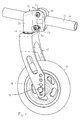
- the steering wheel 10 illustrated in the drawing is between the two legs 11, 11 'of a steering wheel fork 12 rotatable by means of a horizontally extending bearing axis 13 added.
- the legs 11, 11 'of the steering wheel fork are with several perforations spaced from each other 14 provided in the interest of a change in inclination of a wheelchair, not shown, different Allow installations of the steering wheel 10.
- the steering wheel adapter 16 is on a clamp 20 trained storage console in the following to be explained Way attached. Grips around the clamp 16 together with a clamp counterpart 21 a frame tube 23 of a side frame part 24 of the not shown wheelchair chassis frame and is on the Frame tube 23 releasably set. Through the frame tube 23 extends through a pin 25 which in recesses 26, 27 of the clamp 20 and the clamp counterpart 21 is included.
- the bearing bracket designed as a clamp 20 has on the technological counterpart of the clamp 21 Side a contact surface 28 and through over and under that Frame tube 23 projecting sections extend Through bores 29, 30 through that with corresponding Through holes 31, 32 in the clamp counterpart 21 are in line. Furthermore, the contact surface 28 the clamp 20 in the area of the lower through hole 30 provided with a spur 33, the arranged concentrically to the upper through hole 29 and is provided with teeth aligned with it.
- the steering wheel adapter 16 has a bearing part 36 which from the steering wheel fork 12 as a vertical axis projecting journal rotatably receives, and one of the bearing part 36 laterally projecting flange 37.
- the flange 37 is of a upper through hole 38 and a lower slot 39 broken through.
- the slot 39 is concentric the upper through hole 38 and the distance between the through hole 38 and the elongated hole 39 is equal to the distance between the through holes 29, 30 of the clamp 20.
- the Steering wheel adapter 16 on that facing away from the bearing part 36 Side of the flange 37 one of the contact surface 28 of the Clamp 20 adapted contact surface 40, which in Area of the elongated hole 39 with one in the drawing is not counter toothing shown to the spur toothing 33 the clamp 20 is equipped.
- the steering wheel adapter 16 is on with its contact surface 40 the contact surface 28 of the clamp 20 with the latter clamped by means of two clamping screws 41, 42, which by the flange 37 of the steering wheel adapter 16 and the clamp 20 and the clamp counterpart 21 extend through.
- the tensioning screws 41, 42 have heads protruding radially over the screw shafts, the with washers in between the edges of the Through hole 38 and the elongated hole 39 in the flange 37 reach behind the steering wheel adapter.
- the screw heads distal ends of the clamping screws 41, 42 are formed as threaded sections over the clamp counterpart 21 protrude and screwed onto the nuts are.
- the clamps are on the one hand 20 and the clamp counterpart 21 under clamping the frame tube 23 held firmly on this and the steering wheel adapter 16 is with its contact surface 40 with the Contact surface 28 of the clamp 20 clamped, the Counter toothing of the steering wheel adapter 16 in a form-fitting manner the end teeth 33 of the clamp 20 engages.
- the steering wheel adapter 16 is selected Mounting position held securely.
- the tensioning screws must first be used 41, 42 are solved so far that the counter-toothing of Steering wheel adapter 16 and the front teeth 33 of the clamp 20 disengaged. Then the steering wheel adapter 16 within the given by the slot 39 Limits pivotable about the clamping screw 41 as the bearing axis and by tightening the clamping screws again 41, 42 can be set in the new setting position, in turn the counter-toothing of the steering wheel adapter 16 in the Front toothing 33 of the clamping piece 20 engages positively.
- Such pivoting of the steering wheel adapter 16 relative to the clamp 20 is necessary, for example, if by moving the steering wheel 10 within the steering wheel fork 12 the inclination of the wheelchair in its entirety is changed, for example in the interest of an individual User needs to change seat inclination.
- By swiveling the steering wheel adapter 16 compared to the clamp 20 is reached that even after a change in the inclination of the wheelchair in its entirety the vertical axes of the steering wheels are largely extend vertically, which is in the interest of good driving characteristics a wheelchair is desired.
Landscapes
- Health & Medical Sciences (AREA)
- Life Sciences & Earth Sciences (AREA)
- Animal Behavior & Ethology (AREA)
- General Health & Medical Sciences (AREA)
- Public Health (AREA)
- Veterinary Medicine (AREA)
- Engineering & Computer Science (AREA)
- Mechanical Engineering (AREA)
- Steering Controls (AREA)
- Developing Agents For Electrophotography (AREA)
- Prostheses (AREA)
- Automatic Cycles, And Cycles In General (AREA)
Applications Claiming Priority (2)
| Application Number | Priority Date | Filing Date | Title |
|---|---|---|---|
| DE29817702U DE29817702U1 (de) | 1998-10-05 | 1998-10-05 | Rollstuhl |
| DE29817702U | 1998-10-05 |
Publications (2)
| Publication Number | Publication Date |
|---|---|
| EP0992226A2 true EP0992226A2 (fr) | 2000-04-12 |
| EP0992226A3 EP0992226A3 (fr) | 2001-01-03 |
Family
ID=8063460
Family Applications (1)
| Application Number | Title | Priority Date | Filing Date |
|---|---|---|---|
| EP99118421A Withdrawn EP0992226A3 (fr) | 1998-10-05 | 1999-09-17 | Fauteuil roulant |
Country Status (2)
| Country | Link |
|---|---|
| EP (1) | EP0992226A3 (fr) |
| DE (1) | DE29817702U1 (fr) |
Cited By (4)
| Publication number | Priority date | Publication date | Assignee | Title |
|---|---|---|---|---|
| CN102442623A (zh) * | 2011-12-17 | 2012-05-09 | 苏州先锋物流装备科技有限公司 | 一种堆垛车用可调节式平衡轮 |
| CN104495701A (zh) * | 2014-12-23 | 2015-04-08 | 苏州先锋物流装备科技有限公司 | 一种可调节高度的平衡轮结构 |
| CN113815350A (zh) * | 2021-10-14 | 2021-12-21 | 广州亚华五金设备厂 | 一种新型万向轮 |
| US12420587B2 (en) | 2023-09-29 | 2025-09-23 | Permobil, Inc. | Caster adjustment assembly for a wheelchair |
Families Citing this family (6)
| Publication number | Priority date | Publication date | Assignee | Title |
|---|---|---|---|---|
| DE19957579A1 (de) * | 1999-11-02 | 2001-05-03 | Rolko Kohlgrueber Gmbh | Radgabel, insbesondere Lenkgabel, für vorzugsweise Rollstühle oder dergleichen |
| DE102005051556B4 (de) * | 2005-10-26 | 2008-04-17 | Novakovic, Christine | Schubkarre mit Stützvorrichtung |
| DE602006012031D1 (de) * | 2006-06-30 | 2010-03-18 | Invacare Internat S A R L | Winkelverstellvorrichtung einer Schwenkrolle für einen Rollstuhl |
| EP2505384A1 (fr) * | 2011-04-01 | 2012-10-03 | Invacare International Sàrl | Fauteuil roulant doté d'un réglage de l'axe de pivotement de la roue pivotante |
| EP3620146B1 (fr) | 2018-09-06 | 2023-02-15 | Invacare International GmbH | Assemblage de support de roue orientable pour fauteuil roulant et fauteuil roulant comprenant un tel assemblage |
| EP3730113A1 (fr) * | 2019-04-23 | 2020-10-28 | Invacare International GmbH | Fauteuil roulant anti-basculement |
Citations (1)
| Publication number | Priority date | Publication date | Assignee | Title |
|---|---|---|---|---|
| DE29607440U1 (de) | 1996-04-24 | 1996-08-01 | Sopur Medizintechnik GmbH, 69254 Malsch | Rollstuhl |
Family Cites Families (5)
| Publication number | Priority date | Publication date | Assignee | Title |
|---|---|---|---|---|
| US4500102A (en) * | 1982-11-16 | 1985-02-19 | Invacare Corporation | Sports wheelchair |
| DE8631974U1 (de) * | 1986-11-28 | 1987-04-16 | MEYRA Wilhelm Meyer GmbH & Co KG, 4925 Kalletal | Krankenfahrstuhl |
| DE8914424U1 (de) * | 1989-12-07 | 1990-01-25 | MEYRA Wilhelm Meyer GmbH & Co KG, 4925 Kalletal | Rollstuhl |
| US5360224A (en) * | 1991-11-08 | 1994-11-01 | Medical Composite Technology, Inc. | Wheelchair frame assembly and components for use thereon |
| EP0702945A1 (fr) * | 1994-09-13 | 1996-03-27 | Ortopedia Gmbh | Fauteuil roulant avec cadre réglable |
-
1998
- 1998-10-05 DE DE29817702U patent/DE29817702U1/de not_active Expired - Lifetime
-
1999
- 1999-09-17 EP EP99118421A patent/EP0992226A3/fr not_active Withdrawn
Patent Citations (1)
| Publication number | Priority date | Publication date | Assignee | Title |
|---|---|---|---|---|
| DE29607440U1 (de) | 1996-04-24 | 1996-08-01 | Sopur Medizintechnik GmbH, 69254 Malsch | Rollstuhl |
Cited By (5)
| Publication number | Priority date | Publication date | Assignee | Title |
|---|---|---|---|---|
| CN102442623A (zh) * | 2011-12-17 | 2012-05-09 | 苏州先锋物流装备科技有限公司 | 一种堆垛车用可调节式平衡轮 |
| CN102442623B (zh) * | 2011-12-17 | 2016-04-13 | 苏州先锋物流装备科技有限公司 | 一种堆垛车用可调节式平衡轮 |
| CN104495701A (zh) * | 2014-12-23 | 2015-04-08 | 苏州先锋物流装备科技有限公司 | 一种可调节高度的平衡轮结构 |
| CN113815350A (zh) * | 2021-10-14 | 2021-12-21 | 广州亚华五金设备厂 | 一种新型万向轮 |
| US12420587B2 (en) | 2023-09-29 | 2025-09-23 | Permobil, Inc. | Caster adjustment assembly for a wheelchair |
Also Published As
| Publication number | Publication date |
|---|---|
| DE29817702U1 (de) | 1999-01-07 |
| EP0992226A3 (fr) | 2001-01-03 |
Similar Documents
| Publication | Publication Date | Title |
|---|---|---|
| DE69718418T2 (de) | Rollstuhl mit Radsturzeinstellung | |
| DE19853579C2 (de) | Vorrichtung zur Befestigung einer Achsmeßeinrichtung an einer Felge eines Rades an einem Kraftfahrzeug | |
| DE3619125C1 (de) | Aufnahmevorrichtung fuer eine verstellbare Lenksaeule eines Kraftwagens | |
| EP0538609A1 (fr) | Chaise roulante réglable | |
| EP0992226A2 (fr) | Fauteuil roulant | |
| DE60003808T2 (de) | Leiterausgleichsvorrichtung | |
| EP0538610B1 (fr) | Chaise roulante | |
| DE68902481T2 (de) | Vorrichtung fuer verstellbare stuehle. | |
| DE10310018A1 (de) | Vorrichtung zum Befestigen eines Gurtschlosses eines Sicherheitsgurtes an einem Fahrzeugsitz | |
| DE4309561A1 (de) | Gabelhubwagen mit einem Antriebsrad und seitlichen Stützrädern | |
| CH682649A5 (de) | Vorrichtung zur höheneinstellbaren Befestigung eines einen Schienenschalter aufnehmenden Gehäuses. | |
| DE19512284A1 (de) | Fahrzeugsitz, insbesondere Staplersitz | |
| DE8914424U1 (de) | Rollstuhl | |
| DE3045325A1 (de) | Haltevorrichtung fuer kotfluegel an lastkraftwagen, anhaengern oder sonstigen fahrzeugen | |
| DE29911151U1 (de) | Vorrichtung zum mehrlagigen Einbauen einer Straßendecke | |
| DE102016217111A1 (de) | Dachträgervorrichtung | |
| EP0944517A1 (fr) | Support pour bicyclettes | |
| DE29605439U1 (de) | Rollstuhl | |
| DE9414356U1 (de) | Hebebrücke mit einstellbaren Standfüßen | |
| DE3521836A1 (de) | Vorrichtung zum verstellen eines fahrzeugsitzes | |
| EP0463340B1 (fr) | Porte-bagages réglable pour véhicules à deux roues | |
| DE3501157C1 (de) | Halterung für einen Außenrückblickspiegel | |
| DE3237289C2 (fr) | ||
| DE4128277C1 (fr) | ||
| DE20214246U1 (de) | Zweierkombination vorzugsweise spiegelbildlich angeordneter Lenk- und Antriebseinheiten |
Legal Events
| Date | Code | Title | Description |
|---|---|---|---|
| PUAI | Public reference made under article 153(3) epc to a published international application that has entered the european phase |
Free format text: ORIGINAL CODE: 0009012 |
|
| AK | Designated contracting states |
Kind code of ref document: A2 Designated state(s): AT BE CH CY DE DK ES FI FR GB GR IE IT LI LU MC NL PT SE |
|
| AX | Request for extension of the european patent |
Free format text: AL;LT;LV;MK;RO;SI |
|
| PUAL | Search report despatched |
Free format text: ORIGINAL CODE: 0009013 |
|
| AK | Designated contracting states |
Kind code of ref document: A3 Designated state(s): AT BE CH CY DE DK ES FI FR GB GR IE IT LI LU MC NL PT SE |
|
| AX | Request for extension of the european patent |
Free format text: AL;LT;LV;MK;RO;SI |
|
| AKX | Designation fees paid |
Free format text: AT BE CH CY DE DK ES FI FR GB GR IE IT LI LU MC NL PT SE |
|
| STAA | Information on the status of an ep patent application or granted ep patent |
Free format text: STATUS: THE APPLICATION IS DEEMED TO BE WITHDRAWN |
|
| 18D | Application deemed to be withdrawn |
Effective date: 20010704 |