EP0992592A2 - System zur retardierten Kühlung mit körnigem Wärmedämmaterial - Google Patents
System zur retardierten Kühlung mit körnigem Wärmedämmaterial Download PDFInfo
- Publication number
- EP0992592A2 EP0992592A2 EP99307669A EP99307669A EP0992592A2 EP 0992592 A2 EP0992592 A2 EP 0992592A2 EP 99307669 A EP99307669 A EP 99307669A EP 99307669 A EP99307669 A EP 99307669A EP 0992592 A2 EP0992592 A2 EP 0992592A2
- Authority
- EP
- European Patent Office
- Prior art keywords
- rings
- insulation material
- granular insulation
- conveyor
- station
- Prior art date
- Legal status (The legal status is an assumption and is not a legal conclusion. Google has not performed a legal analysis and makes no representation as to the accuracy of the status listed.)
- Withdrawn
Links
Images


Classifications
-
- B—PERFORMING OPERATIONS; TRANSPORTING
- B21—MECHANICAL METAL-WORKING WITHOUT ESSENTIALLY REMOVING MATERIAL; PUNCHING METAL
- B21B—ROLLING OF METAL
- B21B37/00—Control devices or methods specially adapted for metal-rolling mills or the work produced thereby
- B21B37/28—Control of flatness or profile during rolling of strip, sheets or plates
- B21B37/30—Control of flatness or profile during rolling of strip, sheets or plates using roll camber control
- B21B37/32—Control of flatness or profile during rolling of strip, sheets or plates using roll camber control by cooling, heating or lubricating the rolls
-
- C—CHEMISTRY; METALLURGY
- C21—METALLURGY OF IRON
- C21D—MODIFYING THE PHYSICAL STRUCTURE OF FERROUS METALS; GENERAL DEVICES FOR HEAT TREATMENT OF FERROUS OR NON-FERROUS METALS OR ALLOYS; MAKING METAL MALLEABLE, e.g. BY DECARBURISATION OR TEMPERING
- C21D9/00—Heat treatment, e.g. annealing, hardening, quenching or tempering, adapted for particular articles; Furnaces therefor
- C21D9/52—Heat treatment, e.g. annealing, hardening, quenching or tempering, adapted for particular articles; Furnaces therefor for wires; for strips ; for rods of unlimited length
- C21D9/54—Furnaces for treating strips or wire
- C21D9/56—Continuous furnaces for strip or wire
- C21D9/573—Continuous furnaces for strip or wire with cooling
- C21D9/5732—Continuous furnaces for strip or wire with cooling of wires; of rods
-
- B—PERFORMING OPERATIONS; TRANSPORTING
- B21—MECHANICAL METAL-WORKING WITHOUT ESSENTIALLY REMOVING MATERIAL; PUNCHING METAL
- B21C—MANUFACTURE OF METAL SHEETS, WIRE, RODS, TUBES, PROFILES OR LIKE SEMI-MANUFACTURED PRODUCTS OTHERWISE THAN BY ROLLING; AUXILIARY OPERATIONS USED IN CONNECTION WITH METAL-WORKING WITHOUT ESSENTIALLY REMOVING MATERIAL
- B21C47/00—Winding-up, coiling or winding-off metal wire, metal band or other flexible metal material characterised by features relevant to metal processing only
- B21C47/26—Special arrangements with regard to simultaneous or subsequent treatment of the material
-
- C—CHEMISTRY; METALLURGY
- C21—METALLURGY OF IRON
- C21D—MODIFYING THE PHYSICAL STRUCTURE OF FERROUS METALS; GENERAL DEVICES FOR HEAT TREATMENT OF FERROUS OR NON-FERROUS METALS OR ALLOYS; MAKING METAL MALLEABLE, e.g. BY DECARBURISATION OR TEMPERING
- C21D1/00—General methods or devices for heat treatment, e.g. annealing, hardening, quenching or tempering
- C21D1/84—Controlled slow cooling
Definitions
- This invention relates to rolling mills producing hot rolled steel products such as rods, bars and the like, and is concerned in particular with an improved system and method for cooling such products at retarded cooling rates.
- the objective of the present invention is to overcome the drawbacks associated with the above described prior art systems by embedding the rings being transported on the conveyor in granular insulation material. By doing so, exposure of the ring surfaces to ambient air is significantly minimized, with a concomitant reduction in the development of surface scale.
- Collateral advantages include more uniform cooling, and an ability to more closely control cooling rates, for example by either heating or cooling the granular material prior to its application to the product rings.
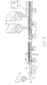
- a continuous belt 12 of sheet steel or other appropriate heat resistant material extends between rolls 14a, 14b at least one of which is driven by a conventional drive (not shown) to move the upper belt portion from left to right as viewed in the drawing.
- the belt is supported at spaced locations between the rolls 14a, 14b by rollers indicated typically at 16, which also may be driven.
- Hot rolled steel rod is received from a rolling mill and directed downwardly by a pinch roll unit 19 and rollerized guide mechanism 20 to a laying head 22 which forms the rod into a continuous series of rings 24.
- a feeder mechanism 26 deposits a base layer 28 of a preheated granular insulation material on the belt 12.
- the insulation material may typically comprise dolomite, silica, sand or the like having an average grain or particle size ranging from about 1 to 8 mm.
- the rings 24 emerging from the laying head 22 are deposited in an overlapping non-concentric pattern on the insulation base layer 28, and are immediately covered by a top layer 30 of preheated granular insulation material applied by second feeder mechanisms 32.
- the rod rings will be laid on the conveyor at an elevated temperature above about 500°C, and the granular insulation will be preheated to ⁇ 100°C of that laying temperature, thereby resulting in the rod being cooled on the conveyor at a retarded rate of the order of 0.05 to 1°C/sec. It will be understood, of course, that this is but one of a myriad of different retarded cooling processes that may be carried out with the disclosed system. Cooling rates will vary depending on the temperature of the rod being laid on the conveyor, the temperature and/or type of granular insulation, and other factors, including the optional use of insulating covers 34 or the like to further retard cooling. Under certain conditions, it may be desirable to cool rather than preheat the granular insulation material.
- the rings 24 pass over driven mutually spaced rollers 36 before being received in a reforming chamber 38 where they are gathered into upstanding cylindrical coils.
- the granular insulation material drops between the rollers 36 into a hopper 40.
- An auger 45 moves the insulation material laterally from the hopper to a bucket conveyor 44 or other like conveying mechanism which serves to recirculate the granular insulation material back to the feeder mechanism 32, and via an auxiliary conveyor 47 to the feeder mechanism 26.
- the granular insulation material will be continuously reheated by the heat given off by the rings on the conveyor, some additional reheating may be required, and to this end heaters 46 may be provided along the path of the conveyor 44 and/or beneath the belt 12.
- the upper end of the reforming chamber 38 is of a known design, as disclosed for example in US Patent Nos. 5,501,410 (Starvaski) and 5,735,477 (Shore et al), and includes a nose cone 40 suspended by an iris mechanism 42 which may be moved into and out of the path of ring descent.
- Insulated pots 44 are movable on driven roller conveyor segments 46a - 46d from a waiting station "A" to a coil receiving position "B" at the reforming chamber 38, and from there to a holding station "C".
- Each pot has an inner core 48 which co-operates with a surrounding insulated wall to define an annular chamber 50.
- Piston cylinder units 52 are operable to elevate the roller conveyor segment 46b, thereby raising the pot 44 supported thereon to place its core 48 in supportive contact with the nose cone 40. This frees the iris mechanism 42 for retraction, thereby allowing rings to descend over the nose cone 40 and into the annular chamber 50 of the underlying pot for collection into a coil.
- the iris mechanism 42 is closed and the conveyor segment 46b is lowered, resulting in the nose cone 40 being redeposited on the iris.
- the filled pot is then shifted to the holding station C where it is covered by a lid 54.
- another empty pot is moved into the coil receiving position B and the entire operation is repeated.
- the granular insulation material dropping between the spaced rollers 36 is directed downwardly into the annular chamber 50 of a pot at the waiting station A.
- the filled pot is then shifted to the coil receiving position B, and its place at the waiting station A is taken by another empty pot (not shown).
- the pots are provided with gate mechanisms 56 at the bottoms of the annular chambers 50.
- the gate mechanism of the pot at the receiving position B is opened to control the discharge of granular insulation material downwardly through the spaced rollers of the conveyor segment 46b onto a conveyor belt 58 for return to the bucket conveyor 44.
- the gradually lowering level of the granular insulation in the pot chamber serves as a descending coil support which maintains the top of the accumulating coil at a relatively constant level.
- the present invention offers a number of significant advantages not available with prior art systems.
- Of particular importance is the immediate embedding of the rings 24 emerging from the laying head 22 in the granular insulation material. By doing so, the development of surface scale is significantly minimized, while at the same time making it possible to achieve a more uniform and controllable rate of retarded cooling.
- the granular insulation material can either be recovered and recirculated back to its initial points of application, or it can serve a continued support function in the insulated pots being employed at the reforming chamber.
Landscapes
- Engineering & Computer Science (AREA)
- Chemical & Material Sciences (AREA)
- Mechanical Engineering (AREA)
- Physics & Mathematics (AREA)
- Thermal Sciences (AREA)
- Crystallography & Structural Chemistry (AREA)
- Materials Engineering (AREA)
- Metallurgy (AREA)
- Organic Chemistry (AREA)
- Heat Treatments In General, Especially Conveying And Cooling (AREA)
- Winding, Rewinding, Material Storage Devices (AREA)
Applications Claiming Priority (4)
| Application Number | Priority Date | Filing Date | Title |
|---|---|---|---|
| US10365798P | 1998-10-09 | 1998-10-09 | |
| US103657P | 1998-10-09 | ||
| US09/392,112 US6331219B1 (en) | 1998-10-09 | 1999-09-08 | Retarded cooling system with granular insulation material |
| US392112 | 1999-09-08 |
Publications (2)
| Publication Number | Publication Date |
|---|---|
| EP0992592A2 true EP0992592A2 (de) | 2000-04-12 |
| EP0992592A3 EP0992592A3 (de) | 2001-06-13 |
Family
ID=26800708
Family Applications (1)
| Application Number | Title | Priority Date | Filing Date |
|---|---|---|---|
| EP99307669A Withdrawn EP0992592A3 (de) | 1998-10-09 | 1999-09-29 | System zur retardierten Kühlung mit körnigem Wärmedämmaterial |
Country Status (8)
| Country | Link |
|---|---|
| US (1) | US6331219B1 (de) |
| EP (1) | EP0992592A3 (de) |
| JP (1) | JP3291277B2 (de) |
| KR (1) | KR100360637B1 (de) |
| CN (1) | CN1123406C (de) |
| BR (1) | BR9904454A (de) |
| CA (1) | CA2282973A1 (de) |
| TW (1) | TW436527B (de) |
Cited By (1)
| Publication number | Priority date | Publication date | Assignee | Title |
|---|---|---|---|---|
| US8635895B2 (en) | 2008-07-07 | 2014-01-28 | Siemens Aktiengesellschaft | Method for cooling a hot strip wound to a hot strip bundle, a device for cooling a hot strip, a control and/or a regulation device and metal strip |
Families Citing this family (3)
| Publication number | Priority date | Publication date | Assignee | Title |
|---|---|---|---|---|
| US20080019805A1 (en) * | 2006-07-19 | 2008-01-24 | Bowler Martyn A | Method of transporting and heat treating coils of hot rolled products in a rolling mill |
| RU2343029C1 (ru) * | 2007-04-09 | 2009-01-10 | ООО "Корад" | Способ регулируемого замедленного охлаждения горячекатаного толстого листа |
| CN110254801A (zh) * | 2019-06-05 | 2019-09-20 | 盐城市联鑫钢铁有限公司 | 一种高线集卷托板控圈装置 |
Family Cites Families (19)
| Publication number | Priority date | Publication date | Assignee | Title |
|---|---|---|---|---|
| FR81035E (fr) | 1962-01-30 | 1963-07-19 | Mi-bas ou chaussette avec talon en caoutchouc crêpé vulcanisé | |
| US3320101A (en) | 1963-05-24 | 1967-05-16 | Morgan Construction Co | Hot rolled steel rod |
| GB1040760A (en) * | 1962-12-21 | 1966-09-01 | Davy & United Eng Co Ltd | Improvements in or relating to heat treatment of steel rod |
| US3378248A (en) | 1966-04-26 | 1968-04-16 | United States Steel Corp | Coil support apparatus |
| US3525507A (en) | 1966-10-25 | 1970-08-25 | Huettenwerk Oberhausen Ag | Fluidized-bed system for patenting steel wire |
| US3506468A (en) * | 1967-08-07 | 1970-04-14 | Huettenwerk Oberhausen Ag | Method of patenting steel wire |
| US3930900A (en) | 1974-10-21 | 1976-01-06 | Morgan Construction Company | Process for cooling hot rolled steel rod |
| US3940961A (en) | 1974-11-18 | 1976-03-02 | Morgan Construction Company | Apparatus for cooling hot rolled steel rod by forced air convection or by supplying heat |
| JPS5395131A (en) * | 1977-01-31 | 1978-08-19 | Agency Of Ind Science & Technol | Removing method for scale of steel |
| US4382586A (en) | 1978-05-15 | 1983-05-10 | Reese Thurston F | Metal cooling bed for controlling rate of cooling |
| LU81035A1 (fr) * | 1979-03-12 | 1980-09-24 | Arbed | Procede et installation pour le refroidissement controle de produits siderurgiques |
| JPS6043808B2 (ja) * | 1979-12-14 | 1985-09-30 | 新日本製鐵株式会社 | 熱間圧延線材の冷却設備 |
| US4468262A (en) | 1980-09-10 | 1984-08-28 | Nippon Steel Corporation | Method of cooling hot-rolled wire rods |
| US4410373A (en) | 1981-09-30 | 1983-10-18 | Kemp Willard E | Process for heat treatment of a metal workpiece |
| DE3233533A1 (de) | 1982-09-10 | 1984-03-15 | Uhde Gmbh, 4600 Dortmund | Verfahren zur wiederaufheizung und foerderung eines koernigen waermetraegers sowie vorrichtung insbesondere zu dessen durchfuehrung |
| FR2575683B1 (fr) | 1985-01-04 | 1987-01-30 | Pont A Mousson | Procede et installation pour la fabrication continue de tuyaux en fonte a graphite spheroidal a structure controlee |
| US4861394A (en) | 1987-07-30 | 1989-08-29 | The Babcock & Wilcox Company | Controlled slow cooling of steel tubulars |
| US5101652A (en) | 1990-07-26 | 1992-04-07 | Allegheny Ludlum Corporation | Insulating heat retention system and method |
| JPH0899114A (ja) * | 1994-09-30 | 1996-04-16 | Nippon Steel Corp | 高温鋼材の泡沫冷却方法 |
-
1999
- 1999-09-08 US US09/392,112 patent/US6331219B1/en not_active Expired - Fee Related
- 1999-09-22 CA CA002282973A patent/CA2282973A1/en not_active Abandoned
- 1999-09-29 TW TW088116694A patent/TW436527B/zh active
- 1999-09-29 EP EP99307669A patent/EP0992592A3/de not_active Withdrawn
- 1999-10-07 BR BR9904454-4A patent/BR9904454A/pt not_active IP Right Cessation
- 1999-10-07 CN CN99121086A patent/CN1123406C/zh not_active Expired - Fee Related
- 1999-10-08 KR KR1019990043350A patent/KR100360637B1/ko not_active Expired - Fee Related
- 1999-10-08 JP JP28841499A patent/JP3291277B2/ja not_active Expired - Fee Related
Cited By (1)
| Publication number | Priority date | Publication date | Assignee | Title |
|---|---|---|---|---|
| US8635895B2 (en) | 2008-07-07 | 2014-01-28 | Siemens Aktiengesellschaft | Method for cooling a hot strip wound to a hot strip bundle, a device for cooling a hot strip, a control and/or a regulation device and metal strip |
Also Published As
| Publication number | Publication date |
|---|---|
| KR20000028920A (ko) | 2000-05-25 |
| BR9904454A (pt) | 2000-08-29 |
| TW436527B (en) | 2001-05-28 |
| US6331219B1 (en) | 2001-12-18 |
| JP2000158032A (ja) | 2000-06-13 |
| JP3291277B2 (ja) | 2002-06-10 |
| KR100360637B1 (ko) | 2002-11-13 |
| EP0992592A3 (de) | 2001-06-13 |
| CN1250694A (zh) | 2000-04-19 |
| CN1123406C (zh) | 2003-10-08 |
| CA2282973A1 (en) | 2000-04-09 |
Similar Documents
| Publication | Publication Date | Title |
|---|---|---|
| AU624831B2 (en) | Continuous production of steel strip and sheet based on continuous casting | |
| US4289944A (en) | Apparatus for reheating, storing and conveying cast bars | |
| AU737631B2 (en) | Method to control the axial position of slabs emerging from continuous casting and relative device | |
| AU701827B2 (en) | Method and device for introducing bulk material into a rotary-hearth furnace | |
| US6331219B1 (en) | Retarded cooling system with granular insulation material | |
| JP2001520364A (ja) | 回転炉床炉への装入装置 | |
| US4427371A (en) | Pusher furnace with soak zone lifter | |
| US5318276A (en) | Apparatus for conveying rolled stock wound into coils in the reeling installation area | |
| EP0354001B1 (de) | Vorrichtung zum Biegen von Glasscheiben | |
| EP0033194B1 (de) | Verfahren und Anlage zum Walzen von Stahl | |
| RU2188089C2 (ru) | Система и способ для охлаждения горячекатаного изделия с пониженной скоростью охлаждения | |
| JPS5820301A (ja) | 鋼材の熱間圧延方法および熱処理炉 | |
| KR20100005844A (ko) | 선재 권취장치 및 방법 | |
| MXPA99009311A (en) | Delayed cooling system with aislamie granular material | |
| US4807457A (en) | Line to cool wound bundles of rolled wire and rod | |
| US4042384A (en) | Production of metal strip from powder | |
| JP3777070B2 (ja) | 線材の巻取方法 | |
| AU631665B2 (en) | Production of flat products | |
| RU2037537C1 (ru) | Установка для отжига твч калиброванной стали | |
| CS216904B2 (en) | Appliance for continuous production of the metal band from the powder | |
| US3443605A (en) | Wire or rod handling method and apparatus | |
| JPH01306001A (ja) | 脱炭抑制を図った鉄鋼素材の熱間圧延方法 | |
| KR101008151B1 (ko) | 선재코일 집적기의 코일 정리장치 | |
| JPH01123034A (ja) | 熱間圧延線材の直接熱処理方法およびその装置 | |
| US6238210B1 (en) | Furnaces for reheating siderurgical products |
Legal Events
| Date | Code | Title | Description |
|---|---|---|---|
| PUAI | Public reference made under article 153(3) epc to a published international application that has entered the european phase |
Free format text: ORIGINAL CODE: 0009012 |
|
| AK | Designated contracting states |
Kind code of ref document: A2 Designated state(s): AT BE CH CY DE DK ES FI FR GB GR IE IT LI LU MC NL PT SE |
|
| AX | Request for extension of the european patent |
Free format text: AL;LT;LV;MK;RO;SI |
|
| RIN1 | Information on inventor provided before grant (corrected) |
Inventor name: PUCHOVSKY, MELICHER Inventor name: SHORE, MICHAEL T. |
|
| PUAL | Search report despatched |
Free format text: ORIGINAL CODE: 0009013 |
|
| RIC1 | Information provided on ipc code assigned before grant |
Free format text: 7C 21D 9/573 A, 7B 21C 47/26 B, 7C 21D 1/70 B |
|
| AK | Designated contracting states |
Kind code of ref document: A3 Designated state(s): AT BE CH CY DE DK ES FI FR GB GR IE IT LI LU MC NL PT SE |
|
| AX | Request for extension of the european patent |
Free format text: AL;LT;LV;MK;RO;SI |
|
| 17P | Request for examination filed |
Effective date: 20011127 |
|
| AKX | Designation fees paid |
Free format text: AT BE CH CY DE DK ES FI FR GB GR IE IT LI LU MC NL PT SE |
|
| 17Q | First examination report despatched |
Effective date: 20030602 |
|
| STAA | Information on the status of an ep patent application or granted ep patent |
Free format text: STATUS: THE APPLICATION IS DEEMED TO BE WITHDRAWN |
|
| 18D | Application deemed to be withdrawn |
Effective date: 20040719 |