EP0992650A2 - Porte souple - Google Patents
Porte souple Download PDFInfo
- Publication number
- EP0992650A2 EP0992650A2 EP99119472A EP99119472A EP0992650A2 EP 0992650 A2 EP0992650 A2 EP 0992650A2 EP 99119472 A EP99119472 A EP 99119472A EP 99119472 A EP99119472 A EP 99119472A EP 0992650 A2 EP0992650 A2 EP 0992650A2
- Authority
- EP
- European Patent Office
- Prior art keywords
- strip
- post
- flexible
- door according
- strips
- Prior art date
- Legal status (The legal status is an assumption and is not a legal conclusion. Google has not performed a legal analysis and makes no representation as to the accuracy of the status listed.)
- Withdrawn
Links
- 238000004804 winding Methods 0.000 claims abstract description 15
- 239000002184 metal Substances 0.000 claims abstract description 13
- 239000004744 fabric Substances 0.000 claims abstract description 10
- 230000003014 reinforcing effect Effects 0.000 claims abstract description 7
- 239000000463 material Substances 0.000 claims abstract description 5
- 229920003023 plastic Polymers 0.000 claims abstract description 5
- 239000004033 plastic Substances 0.000 claims abstract description 5
- 229920002994 synthetic fiber Polymers 0.000 claims abstract description 5
- 238000005096 rolling process Methods 0.000 claims description 5
- 229920003002 synthetic resin Polymers 0.000 claims description 4
- 239000000057 synthetic resin Substances 0.000 claims description 4
- 230000003247 decreasing effect Effects 0.000 claims description 2
- 229920001225 polyester resin Polymers 0.000 claims description 2
- 239000004645 polyester resin Substances 0.000 claims description 2
- 229920005749 polyurethane resin Polymers 0.000 claims description 2
- 229920000915 polyvinyl chloride Polymers 0.000 claims description 2
- 229920005989 resin Polymers 0.000 claims description 2
- 239000011347 resin Substances 0.000 claims description 2
- 230000006378 damage Effects 0.000 description 3
- 208000027418 Wounds and injury Diseases 0.000 description 1
- 238000010276 construction Methods 0.000 description 1
- 238000005470 impregnation Methods 0.000 description 1
- 208000014674 injury Diseases 0.000 description 1
Images


Classifications
-
- E—FIXED CONSTRUCTIONS
- E06—DOORS, WINDOWS, SHUTTERS, OR ROLLER BLINDS IN GENERAL; LADDERS
- E06B—FIXED OR MOVABLE CLOSURES FOR OPENINGS IN BUILDINGS, VEHICLES, FENCES OR LIKE ENCLOSURES IN GENERAL, e.g. DOORS, WINDOWS, BLINDS, GATES
- E06B9/00—Screening or protective devices for wall or similar openings, with or without operating or securing mechanisms; Closures of similar construction
- E06B9/02—Shutters, movable grilles, or other safety closing devices, e.g. against burglary
- E06B9/08—Roll-type closures
- E06B9/11—Roller shutters
- E06B9/13—Roller shutters with closing members of one piece, e.g. of corrugated sheet metal
-
- E—FIXED CONSTRUCTIONS
- E06—DOORS, WINDOWS, SHUTTERS, OR ROLLER BLINDS IN GENERAL; LADDERS
- E06B—FIXED OR MOVABLE CLOSURES FOR OPENINGS IN BUILDINGS, VEHICLES, FENCES OR LIKE ENCLOSURES IN GENERAL, e.g. DOORS, WINDOWS, BLINDS, GATES
- E06B9/00—Screening or protective devices for wall or similar openings, with or without operating or securing mechanisms; Closures of similar construction
- E06B9/56—Operating, guiding or securing devices or arrangements for roll-type closures; Spring drums; Tape drums; Counterweighting arrangements therefor
- E06B9/58—Guiding devices
- E06B9/581—Means to prevent or induce disengagement of shutter from side rails
-
- E—FIXED CONSTRUCTIONS
- E06—DOORS, WINDOWS, SHUTTERS, OR ROLLER BLINDS IN GENERAL; LADDERS
- E06B—FIXED OR MOVABLE CLOSURES FOR OPENINGS IN BUILDINGS, VEHICLES, FENCES OR LIKE ENCLOSURES IN GENERAL, e.g. DOORS, WINDOWS, BLINDS, GATES
- E06B9/00—Screening or protective devices for wall or similar openings, with or without operating or securing mechanisms; Closures of similar construction
- E06B9/56—Operating, guiding or securing devices or arrangements for roll-type closures; Spring drums; Tape drums; Counterweighting arrangements therefor
- E06B9/58—Guiding devices
- E06B2009/585—Emergency release to prevent damage of shutter or guiding device
Definitions
- the present invention relates to flexible doors of the type comprising:
- Flexible doors of the above-mentioned type include both known rolling doors in which the upper edge of the flexible sheet is fixed to the winding roller so that the sheet is rolled onto the roller, and known doors known as folding or stacking doors, in which the upper edge of the flexible sheet is connected to a fixed upper portion and the flexible sheet has a plurality of reinforcing cross-members of which the bottom one is connected to the winding roller by means of a plurality of vertical straps each of which is guided through through-holes of alternate reinforcing cross-members so that, when the straps are rolled around the winding roller, the flexible sheet is piled up in successive folds, forming a bundle beneath the winding roller.
- the invention relates to doors of the above-mentioned type in which the vertical movement of the flexible sheet is performed at high speed in order to satisfy requirements due to heavy traffic of people and vehicles through the doorway.
- the main object of the present invention is to provide a flexible door of the type indicated above which - in the event of a knock either against the flexible sheet or against the posts - does not have the disadvantages indicated above, and which is of simple and economical construction.
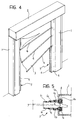
- a flexible rolling door comprises a metal support structure constituted by two vertical posts 1 connected by an upper cross-member 2 in which a winding roller (not shown), driven so as to rotate in two senses, is mounted rotatably in known manner.
- each of the posts 1 is a guide, generally indicated 5, in which the side edges of a flexible sheet 3 slide, the flexible sheet 3 having transverse reinforcing bars 4 and constituting the movable closure element of the door.
- the flexible sheet 3 has its upper edge connected to the winding roller so as to move vertically in two directions as a result of the rotation of the operating roller in the two senses.
- Each guide 5 terminates at the top a predetermined distance, indicated A in Figure 1, from the top of the post 1.
- each metal post 1 has a box-shaped cross-section and has a flat vertical wall 1a facing inwardly relative to the door.
- a vertical slot F formed in the wall 1a extends throughout the height of the post 1, its edges being parallel to one another for the major portion of the height of the post and being inclined so as to diverge outwardly in the upper end portion.
- the wall 1a of the post has a flange 1b bent inwardly at 90°.
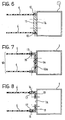
- Each guide 5 comprises two facing, parallel, flexible, vertical strips 6 each of which is fixed, at its outer longitudinal edge, to the metal post 1, and projects from the post towards the door opening.
- This fixing is achieved by the clamping of the longitudinal outer edge of each strip 6 against the bent flange 1b of the post by means of a metal strip 7 superimposed on that edge of the strip and fixed to the bent flange 1b by means of screws, bolts, rivets or the like, as indicated at 8.
- each strip 6 has an upper end portion 6a which is bent outwardly relative to the guide 5.
- each strip 6 has an end edge 9 which is inclined downwardly and inwardly relative to the strip from the upper end of the strip which is fixed to the post 1.
- each strip 6 is spaced vertically from the top of the post 1 (and hence from the cross-member 2) by a predetermined distance, indicated A.
- Each strip 6 is made of plastics material and is constituted by at least one layer of fabric which is made of synthetic fibres and has a high transverse stiffness much greater than its stiffness in the direction of the length of the strip, and which is impregnated with synthetic resin.
- each synthetic-fibre fabric layer comprises warp threads arranged longitudinally and each constituted by a plurality of filaments and weft threads arranged transversely and each constituted by a monofilament having a diameter of between 0.1 and 1 mm, preferably between 0.2 and 0.3 mm.
- the synthetic resin of which the threads of the fabric are made is preferably constituted by a polyester resin and the impregnation resin may be polyvinyl or polyurethane resin.
- each strip 6 deforms resiliently to allow the flexible sheet 3 to come out of the respective guide 5 when the sheet or one of the posts 1 is subjected to a knock, the strip 6 snapping back to its normal position immediately after the flexible sheet has come out.
- the flexible sheet 3 moves in contact with the outer surface of one of the two strips 6 of each guide 5 until, upon completion of the rolling, the lower end portion of the sheet 3 passes beyond the tops of the guides 5.
- the distance A between the tops of the guides 5 and the upper cross-member 2 is such as to allow the lower end portion of the sheet 3 which hangs from the winding roller to be arranged in the normal vertical sliding plane between the two guides 5.
- each of the two strips 6 which form each guide 5 is bent outwardly at its upper end 6a facilitates the above-mentioned re-entry of the sheet 3 into the guides 5.
- each guide 5 is constituted by three superimposed strips 6 1 , 6 2 , 6 3 of decreasing width, starting from the inner strip 6 1 .
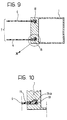
- the outer longitudinal edges of the two strips 6 are clamped by means of screws or the like between two outer strips 10 and an intermediate bar 11 which in turn is fixed to the flat face 1a of the post 1, which may have a closed cross-section, as shown, or an open cross-section.
- the two strips 6 constitute the side walls of a bent, U-shaped element, generally indicated 12.
- the outer edges of the two strips 6 are clamped, by means of screws, rivets or the like between the flanges of an outer channel-section profile 13 and the flanges of an inner channel-section profile 14.
- the base 12a of the bent, U-shaped element 12 is interposed between the base walls of the two sections 13 and 14 which are fixed to the wall 1a of the post 1 by means of screws, rivets or the like.
- each strip 6 has, at its outer longitudinal edge, a portion 15 which is bent at 90° and faces towards the other strip.
- the outer end and the bent portion 15 of each strip 6 are interposed between two angle-sections, indicated 16 and 17, respectively.
- each of the strips 6 which constitute the two guides 5 has an enlarged portion 18 at its outer edge, and the respective post 1 has a vertical slot 19 having a seat 19a of corresponding shape.
- each strip 6 is fixed to the respective post 1 simply by the slipping of the outer edge of the strip into the corresponding slot in the post.
Landscapes
- Engineering & Computer Science (AREA)
- Structural Engineering (AREA)
- Architecture (AREA)
- Civil Engineering (AREA)
- Securing Of Glass Panes Or The Like (AREA)
Applications Claiming Priority (2)
| Application Number | Priority Date | Filing Date | Title |
|---|---|---|---|
| ITTO980832 IT1305117B1 (it) | 1998-10-05 | 1998-10-05 | Porta flessibile ad arrotolamento per uso industriale. |
| ITTO980832 | 1998-10-05 |
Publications (2)
| Publication Number | Publication Date |
|---|---|
| EP0992650A2 true EP0992650A2 (fr) | 2000-04-12 |
| EP0992650A3 EP0992650A3 (fr) | 2000-06-28 |
Family
ID=11417078
Family Applications (1)
| Application Number | Title | Priority Date | Filing Date |
|---|---|---|---|
| EP99119472A Withdrawn EP0992650A3 (fr) | 1998-10-05 | 1999-09-30 | Porte souple |
Country Status (2)
| Country | Link |
|---|---|
| EP (1) | EP0992650A3 (fr) |
| IT (1) | IT1305117B1 (fr) |
Cited By (9)
| Publication number | Priority date | Publication date | Assignee | Title |
|---|---|---|---|---|
| WO2001053648A1 (fr) * | 2000-01-20 | 2001-07-26 | Bernard Simon | Lames semi-rigides pour porte de manutention a rideau souple |
| FR2817586A1 (fr) * | 2000-12-06 | 2002-06-07 | Orditec | Glissieres pour porte a relevage rapide du type a rideau souple avec tubes raidisseurs transversaux |
| WO2001092672A3 (fr) * | 2000-05-30 | 2002-06-27 | Rite Hite Holding Corp | Guide deformable pour portes |
| EP1247932A1 (fr) * | 2001-04-02 | 2002-10-09 | Dynaco International | Dispositif à volet souple |
| WO2003052235A1 (fr) * | 2001-12-14 | 2003-06-26 | Dynaco International S.A. | Dispositif a volet avec chemins de guidage |
| ES2191509A1 (es) * | 1994-06-21 | 2003-09-01 | Ballester Miguel Ange Iglesias | Cerramiento perfeccionado. |
| ES2223204A1 (es) * | 2001-08-10 | 2005-02-16 | Comercial Burgos, S.A. | Cerramiento rapido de cierre vertical perfeccionado. |
| EP2039872A2 (fr) | 2007-09-21 | 2009-03-25 | Oscar Ristolfi | Rail de guidage agencé verticalement et déformable élastiquement pour portes à enroulement avec un vantail flexible coulissant |
| EP1334255B2 (fr) † | 2000-09-25 | 2012-07-18 | Dynaco Europe NV | Dispositif a volet destine a la fermeture d'une baie |
Family Cites Families (3)
| Publication number | Priority date | Publication date | Assignee | Title |
|---|---|---|---|---|
| US4601320A (en) * | 1984-02-09 | 1986-07-22 | Douglas Taylor | Industrial door |
| BE906022A (fr) * | 1986-12-23 | 1987-04-16 | Coenraets B J | Dispositif a volet. |
| EP0775797B1 (fr) * | 1996-01-31 | 1997-06-04 | LAMSFUSS, Norbert | Porte de manutention |
-
1998
- 1998-10-05 IT ITTO980832 patent/IT1305117B1/it active
-
1999
- 1999-09-30 EP EP99119472A patent/EP0992650A3/fr not_active Withdrawn
Cited By (15)
| Publication number | Priority date | Publication date | Assignee | Title |
|---|---|---|---|---|
| ES2191509A1 (es) * | 1994-06-21 | 2003-09-01 | Ballester Miguel Ange Iglesias | Cerramiento perfeccionado. |
| WO2001053648A1 (fr) * | 2000-01-20 | 2001-07-26 | Bernard Simon | Lames semi-rigides pour porte de manutention a rideau souple |
| US6715531B2 (en) | 2000-01-20 | 2004-04-06 | Bernard Simon | Flexible curtain guide mechanism utilizing deflecting frame plates |
| WO2001092672A3 (fr) * | 2000-05-30 | 2002-06-27 | Rite Hite Holding Corp | Guide deformable pour portes |
| EP1334255B2 (fr) † | 2000-09-25 | 2012-07-18 | Dynaco Europe NV | Dispositif a volet destine a la fermeture d'une baie |
| EP1223300A1 (fr) * | 2000-12-06 | 2002-07-17 | Orditec S.A. | Glissière pour porte à relevage rapide du type à rideau souple avec tubes raidisseurs transversaux |
| FR2817586A1 (fr) * | 2000-12-06 | 2002-06-07 | Orditec | Glissieres pour porte a relevage rapide du type a rideau souple avec tubes raidisseurs transversaux |
| WO2002084063A1 (fr) * | 2001-04-02 | 2002-10-24 | Dynaco International, Societe Anonyme | Dispositif a volet souple |
| EP1247932A1 (fr) * | 2001-04-02 | 2002-10-09 | Dynaco International | Dispositif à volet souple |
| US6962188B2 (en) | 2001-04-02 | 2005-11-08 | Dynaco International, S.A. | Device with flexible shutter |
| ES2223204A1 (es) * | 2001-08-10 | 2005-02-16 | Comercial Burgos, S.A. | Cerramiento rapido de cierre vertical perfeccionado. |
| WO2003052235A1 (fr) * | 2001-12-14 | 2003-06-26 | Dynaco International S.A. | Dispositif a volet avec chemins de guidage |
| BE1014544A3 (fr) * | 2001-12-14 | 2003-12-02 | Dynaco Internat | Dispositif a volet avec chemins de guidage. |
| US7409981B2 (en) | 2001-12-14 | 2008-08-12 | Dynaco International S.A. | Shutter device with guideways |
| EP2039872A2 (fr) | 2007-09-21 | 2009-03-25 | Oscar Ristolfi | Rail de guidage agencé verticalement et déformable élastiquement pour portes à enroulement avec un vantail flexible coulissant |
Also Published As
| Publication number | Publication date |
|---|---|
| EP0992650A3 (fr) | 2000-06-28 |
| IT1305117B1 (it) | 2001-04-10 |
| ITTO980832A1 (it) | 2000-04-05 |
Similar Documents
| Publication | Publication Date | Title |
|---|---|---|
| CA2043878C (fr) | Porte souple relevable | |
| DE19739919C2 (de) | Sonnenrollo für ein Kraftfahrzeugdach | |
| EP0508698B1 (fr) | Portail industriel avec longeron débloquable | |
| EP2338716B1 (fr) | Ensemble de pare-soleil et construction de toit ouvert fourni avec celui-ci | |
| US20020124972A1 (en) | Guidance device for a flexible curtain door | |
| EP0992650A2 (fr) | Porte souple | |
| US20080035282A1 (en) | Closure device with a screen presenting flexible side edges | |
| DE69807569T2 (de) | Verbindungsvorrichtung zwischen dem flexiblen Schirm eines Hubtores und seinen Gurtbändern | |
| CA2265356C (fr) | Panneaux souples resistants au vandalisme | |
| US4938273A (en) | Vertically movable door structure | |
| MXPA00000026A (es) | Banda de prensado y cubierta de rodillo de prensado para fabricar papel. | |
| US4088157A (en) | Hood system for covering an automatically operating machine | |
| FI87943B (fi) | Anordning i jalousidoerrar | |
| US5199479A (en) | Skid for a raisable-curtain goods-handling door | |
| NL8400819A (nl) | Deursamenstel. | |
| DE19949329C2 (de) | Schnellauftor | |
| EP0370550A1 (fr) | Store enroulable | |
| DE4021264C2 (de) | Schrägmarkise | |
| GB2093895A (en) | Door assembly | |
| EP2402543B1 (fr) | Portail roulant et procédé de détermination d'un état de charge indésirable par ce type de portail roulant | |
| DE102019205372B4 (de) | Seilantriebssystem für eine Beschattungsvorrichtung eines Fahrzeuginnenraums | |
| JP2005513308A (ja) | 案内路を有するシャッター装置 | |
| EP0305849A2 (fr) | Dispositif pour auvent à longue portée avec rail de guidage | |
| CA2335596A1 (fr) | Porte de manutention | |
| US1034937A (en) | Window-screen. |
Legal Events
| Date | Code | Title | Description |
|---|---|---|---|
| PUAI | Public reference made under article 153(3) epc to a published international application that has entered the european phase |
Free format text: ORIGINAL CODE: 0009012 |
|
| AK | Designated contracting states |
Kind code of ref document: A2 Designated state(s): AT BE CH CY DE DK ES FI FR GB GR IE IT LI LU MC NL PT SE |
|
| AX | Request for extension of the european patent |
Free format text: AL;LT;LV;MK;RO;SI |
|
| PUAL | Search report despatched |
Free format text: ORIGINAL CODE: 0009013 |
|
| AK | Designated contracting states |
Kind code of ref document: A3 Designated state(s): AT BE CH CY DE DK ES FI FR GB GR IE IT LI LU MC NL PT SE |
|
| AX | Request for extension of the european patent |
Free format text: AL;LT;LV;MK;RO;SI |
|
| 17P | Request for examination filed |
Effective date: 20001220 |
|
| AKX | Designation fees paid |
Free format text: DE ES FR GB PT |
|
| GRAP | Despatch of communication of intention to grant a patent |
Free format text: ORIGINAL CODE: EPIDOSNIGR1 |
|
| STAA | Information on the status of an ep patent application or granted ep patent |
Free format text: STATUS: THE APPLICATION IS DEEMED TO BE WITHDRAWN |
|
| 18D | Application deemed to be withdrawn |
Effective date: 20040620 |