EP0992656A1 - Turbomachine pour comprimer ou détendre un fluide comprimable - Google Patents
Turbomachine pour comprimer ou détendre un fluide comprimable Download PDFInfo
- Publication number
- EP0992656A1 EP0992656A1 EP98810999A EP98810999A EP0992656A1 EP 0992656 A1 EP0992656 A1 EP 0992656A1 EP 98810999 A EP98810999 A EP 98810999A EP 98810999 A EP98810999 A EP 98810999A EP 0992656 A1 EP0992656 A1 EP 0992656A1
- Authority
- EP
- European Patent Office
- Prior art keywords
- ring channel
- ring
- channel system
- housing
- opening
- Prior art date
- Legal status (The legal status is an assumption and is not a legal conclusion. Google has not performed a legal analysis and makes no representation as to the accuracy of the status listed.)
- Granted
Links
Images



Classifications
-
- F—MECHANICAL ENGINEERING; LIGHTING; HEATING; WEAPONS; BLASTING
- F01—MACHINES OR ENGINES IN GENERAL; ENGINE PLANTS IN GENERAL; STEAM ENGINES
- F01D—NON-POSITIVE DISPLACEMENT MACHINES OR ENGINES, e.g. STEAM TURBINES
- F01D11/00—Preventing or minimising internal leakage of working-fluid, e.g. between stages
- F01D11/08—Preventing or minimising internal leakage of working-fluid, e.g. between stages for sealing space between rotor blade tips and stator
- F01D11/10—Preventing or minimising internal leakage of working-fluid, e.g. between stages for sealing space between rotor blade tips and stator using sealing fluid, e.g. steam
-
- F—MECHANICAL ENGINEERING; LIGHTING; HEATING; WEAPONS; BLASTING
- F01—MACHINES OR ENGINES IN GENERAL; ENGINE PLANTS IN GENERAL; STEAM ENGINES
- F01D—NON-POSITIVE DISPLACEMENT MACHINES OR ENGINES, e.g. STEAM TURBINES
- F01D5/00—Blades; Blade-carrying members; Heating, heat-insulating, cooling or antivibration means on the blades or the members
- F01D5/12—Blades
- F01D5/22—Blade-to-blade connections, e.g. for damping vibrations
- F01D5/225—Blade-to-blade connections, e.g. for damping vibrations by shrouding
-
- F—MECHANICAL ENGINEERING; LIGHTING; HEATING; WEAPONS; BLASTING
- F04—POSITIVE - DISPLACEMENT MACHINES FOR LIQUIDS; PUMPS FOR LIQUIDS OR ELASTIC FLUIDS
- F04D—NON-POSITIVE-DISPLACEMENT PUMPS
- F04D29/00—Details, component parts, or accessories
- F04D29/08—Sealings
- F04D29/16—Sealings between pressure and suction sides
- F04D29/161—Sealings between pressure and suction sides especially adapted for elastic fluid pumps
- F04D29/164—Sealings between pressure and suction sides especially adapted for elastic fluid pumps of an axial flow wheel
Definitions
- the invention relates to a turbomachine for compression or Relaxing a compressible medium according to the preamble of the claim 1.
- Turbomachines of the type mentioned above are as rotary machines formed and have blade elements along their axis of rotation on, the free blade ends of the inner wall of the Stand opposite flow housing.
- the are flowed through axially to the rotor axis of the medium to be compressed usually guide vane plates fixed on one side to the inner wall of the housing attached to the rotary machine and stand with their free end corresponding Contours on the rotor shaft freely opposite.
- An essential aspect at the optimization of compression efficiency or turbine efficiency is the reduction of leakage currents, i.e. of flow components, of the compressible flowing through the rotary machine Medium between the blade ends or guide blade ends and pass through the contours opposite these.
- labyrinth seals used, which consist of a large number of interlocking contours, which are almost gastight the spaces between the rotating parts and the fixed housing parts together with the guide vane are able to seal. So can the leakage current is significantly reduced when using labyrinth seals the labyrinth seals themselves with a multitude of individual sealing lips be provided, but this seal form has the disadvantage that ever more labyrinth seals are provided inside a rotary machine and these consist of a large number of individual sealing lips, the larger they become the frictional forces exerted, for example, on the rotating blades from the outside act, causing the mechanical stress on the rotating parts within a rotary machine is increased. In addition, it is rarely possible a sufficient number of labyrinth elements for a high sealing effect to accommodate.
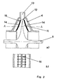
- Figure 2a shows a cross section through a radial compressor, the one central Has rotor shaft 5, which is arranged in the interior of the housing 4 of the radial compressor is.
- a nozzle-like contour 11 is connected to the rotor shaft 5 by which by way of rotation preferably air by centrifugal acceleration from the inside to the outside, is driven through the nozzle opening 12.
- the nozzle opening 12 of the contour 11, an outlet opening 13 is provided within the housing 4, through which the compressed air leaves the radial compressor.
- the invention has for its object a turbomachine in the preamble of claim 1, namely an axial compressor arrangement or to design an axial turbine arrangement such that without known use of labyrinth seals minimizes the leakage flow the disadvantageous friction effects with labyrinth seals, which not least leads to increased material stresses in the control and Guide blades and limit their lifespan should. Rather, it should be based on the measure known for radial compressors found a practical solution to reduce leakage currents be, the Lekagestrom largely contactless between the rotating and to reduce fixed components of the rotary machine.
- a turbomachine for compressing or relaxing a compressible medium, with a rotor, on which at least one row of rotor blades is arranged perpendicular to the rotor axis, the individual rotor blades of which have free rotor blade ends on the radial side, which face the inner wall of a housing surrounding the rotor, through the interior of which the compressible one Medium flows axially to the rotor axis, designed in such a way that an annular channel system is provided radially opposite the free ends of the rotor blade of a rotor blade row within the housing surrounding the rotor.
- the ring channel system preferably extends radially within the housing of the turbomachine around the entire peripheral peripheral edge of a row of moving blades.
- the area of the The ring channel system is open on one side and is delimited by the blade ends such that an opening channel remains on both sides of a row of blades, through the opening channel of which the compressible medium, preferably air, from the interior of the housing, through which the air flows axially, into the interior flows of the ring channel system and exits the air from the ring channel system into the interior of the housing through the second opening channel.
- the opening channels mentioned above correspond in the above case to the intermediate gaps between the rotating and stationary components of the turbine arrangement or the compressor arrangement.
- a ring flow flowing within the ring channel system has the ring channel system and the blade ends at least in areas, which border on the opening channels, surface contours through which the points within the ring channel system where the opening channels open, Pressure conditions are created, which are characterized by the formation of a Set dynamic ring flow within the ring channel system and in correspond approximately to the static pressure conditions in the interior of the housing prevail in the area of the opening channels.
- the ring flow is preferably generated within the ring channel system in which a small proportion of the compressible medium axially passing through the rotary machine, preferably air, passes into the opening channel between the blade end and the housing, preferably through the opening channel, which is provided in the flow direction in front of the blade, and shortly before entering the ring channel system, it has a flow inner contour which is designed such that the flow passing through the opening channel enters the ring channel with a preferred direction.
- a ring flow can be induced within the ring channel system opposite the blade ends, which generates the desired pressure conditions after appropriate design of the inner contour of the ring channel system.
- the blade ends each have a cover band into which the surface contour is incorporated, which is directly opposite the ring channel system.
- the idea underlying the invention is that the flow is lost within of the ring channel system during the operation of the rotary machine so low as possible. For this it is necessary to keep the pressure conditions within of the ring channel system and the interior of the turbomachine in the Adjust areas of the opening channels.
- the static pressure conditions in the The interior of the turbomachine is due to its dimensions and performance given to the machine itself. Accordingly, the ring channel system can be designed in such a way as to prevail in the interior static pressure conditions in the area of the opening channels also in the To generate ring channel system yourself.
- the flow cross section is within the Ring channel system, especially in the area of the opening channels, is reduced in size, that in relation to the flow cross section of the other areas within the Ring channel system, so that a pressure equalization due to a local nozzle effect between the inside of the ring channel and the inside of the flow housing leads.
- Airflow entering the ring channel can be targeted to cooling channels either in the housing the rotary machine and / or in the rotor blades are provided, through the cooling air in the ring duct system can be specifically fed, with a certain specification of the angle of entry of the cooling line into the ring channel system both the direction as well as the flow velocity within of the ring flow setting ring flow can be specified or influenced can.
- the air to be compressed passes the turbomachine shown in partial cross-section from right to left (see Arrow display).
- the blade 1 rotates about the rotor axis 5.
- the end of the blade 2 has a shroud 9 with a surface contour that is S-shaped is formed and roughly the opposite contour of the inner wall of the ring channel 6 corresponds in this area.
- On the side of the sound scoop 1 there is an inlet opening channel 7 in the area of the housing provided, through which air can enter the interior of the annular channel 6.
- the contour of the inlet opening channel 7 is in the region of the transition into the Ring channel 6 formed such that the incoming flow with a preferred direction is introduced into the ring channel.
- the ring channel flow counterclockwise (see Figure 1a) or clockwise (see FIG. 1b).
- the Lekagestrom which is through the gap between the Blade end 2 and the housing 4 would form, is limited Ring channel 6 formed in this section as a diffuser, so that the ring flow the inlet channel opening with relatively low flow velocities overflows, which forms a high dynamic pressure, which is about that corresponds to that before entry into the inlet channel opening 7 in the interior of the rotary machine prevails.
- the inlet opening channel 7 opens inside a curved ring channel course in the ring channel 6 and in particular in the area of the outer curvature of the ring channel, in which the Pressure increase is particularly strict.
- the exit port channel 8 occurs in particular in a concave annular channel wall section in the ring channel in order to flow in the area of the smallest to lie in the ring channel of the prevailing pressure.
- the S-shaped contour at the blade end 2 one into the interior of the housing 4 protruding contour section 9 ', a concave section 9 "and a convex section 9 '' 'on the contour sections 9', 9 '' and 9 '' ' are designed as protruding blade ribs, which arise from the plane of the Raise the blade end 2 and protrude into the ring channel system 6.
- Cooling channel 10 is supplied with cooling air.
- the flow rate of Ring current influenced within the ring channel 6 and its direction of flow become.
- the cooling channel enters the ring channel 6 in such a way that so that an increased ring current is formed counterclockwise.
- a corresponding arrangement for the formation of a ring current clockwise is shown in Figure 3b.
- the blade 1 each has a cooling outlet channel 10, which depending on its direction of entry into the cooling channel 6 Ring flow with regard to their flow direction and flow speed can influence.
- the embodiments according to 4a and b with a cooling system 10 passing through the housing 4 can be combined according to the embodiment 3a, b.
- FIGS. 5 a and b show different embodiments of the shroud 9 shown on a Lautschaufel 2.
- Figure 5a are on the blade end 2 several small rotor blades 15 are provided, which over the Elevate blade end 2 and extend into ring channel 6.
- the representation corresponds to the view within the ring channel on the shroud 9 of the blade end 2.
- Spaced by a gap 14 closes the housing 4 to the left and right of the blade.
- the housing 4 has adjacent to the gaps 14, also ribs 16, which the Lead ring flow within the ring channel 6.
- a Ring flow oriented from left to right and corresponds essentially to that Embodiment according to Figure 1a.
Landscapes
- Engineering & Computer Science (AREA)
- Mechanical Engineering (AREA)
- General Engineering & Computer Science (AREA)
- Structures Of Non-Positive Displacement Pumps (AREA)
- Turbine Rotor Nozzle Sealing (AREA)
Priority Applications (3)
| Application Number | Priority Date | Filing Date | Title |
|---|---|---|---|
| DE59809578T DE59809578D1 (de) | 1998-10-05 | 1998-10-05 | Strömungsmaschine zum Verdichten oder Entspannen eines komprimierbaren Mediums |
| EP98810999A EP0992656B1 (fr) | 1998-10-05 | 1998-10-05 | Turbomachine pour comprimer ou détendre un fluide comprimable |
| US09/397,510 US6264425B1 (en) | 1998-10-05 | 1999-09-17 | Fluid-flow machine for compressing or expanding a compressible medium |
Applications Claiming Priority (1)
| Application Number | Priority Date | Filing Date | Title |
|---|---|---|---|
| EP98810999A EP0992656B1 (fr) | 1998-10-05 | 1998-10-05 | Turbomachine pour comprimer ou détendre un fluide comprimable |
Publications (2)
| Publication Number | Publication Date |
|---|---|
| EP0992656A1 true EP0992656A1 (fr) | 2000-04-12 |
| EP0992656B1 EP0992656B1 (fr) | 2003-09-10 |
Family
ID=8236370
Family Applications (1)
| Application Number | Title | Priority Date | Filing Date |
|---|---|---|---|
| EP98810999A Expired - Lifetime EP0992656B1 (fr) | 1998-10-05 | 1998-10-05 | Turbomachine pour comprimer ou détendre un fluide comprimable |
Country Status (3)
| Country | Link |
|---|---|
| US (1) | US6264425B1 (fr) |
| EP (1) | EP0992656B1 (fr) |
| DE (1) | DE59809578D1 (fr) |
Cited By (2)
| Publication number | Priority date | Publication date | Assignee | Title |
|---|---|---|---|---|
| WO2008011864A1 (fr) * | 2006-07-26 | 2008-01-31 | Mtu Aero Engines Gmbh | Turbine à gaz dotée d'un segment annulaire comprenant un canal de recirculation |
| EP2039872A2 (fr) | 2007-09-21 | 2009-03-25 | Oscar Ristolfi | Rail de guidage agencé verticalement et déformable élastiquement pour portes à enroulement avec un vantail flexible coulissant |
Families Citing this family (17)
| Publication number | Priority date | Publication date | Assignee | Title |
|---|---|---|---|---|
| US6585479B2 (en) | 2001-08-14 | 2003-07-01 | United Technologies Corporation | Casing treatment for compressors |
| CA2496543C (fr) * | 2002-08-23 | 2010-08-10 | Mtu Aero Engines Gmbh | Structure de recirculation d'un turbocompresseur |
| US7074006B1 (en) | 2002-10-08 | 2006-07-11 | The United States Of America As Represented By The Administrator Of National Aeronautics And Space Administration | Endwall treatment and method for gas turbine |
| WO2012052740A1 (fr) * | 2010-10-18 | 2012-04-26 | University Of Durham | Dispositif d'étanchéité pour réduire la fuite de fluide dans une turbine |
| US9995165B2 (en) | 2011-07-15 | 2018-06-12 | United Technologies Corporation | Blade outer air seal having partial coating |
| US9062558B2 (en) * | 2011-07-15 | 2015-06-23 | United Technologies Corporation | Blade outer air seal having partial coating |
| US20150285259A1 (en) * | 2014-04-05 | 2015-10-08 | Arthur John Wennerstrom | Filament-Wound Tip-Shrouded Axial Compressor or Fan Rotor System |
| US10041500B2 (en) * | 2015-12-08 | 2018-08-07 | General Electric Company | Venturi effect endwall treatment |
| US10106246B2 (en) | 2016-06-10 | 2018-10-23 | Coflow Jet, LLC | Fluid systems that include a co-flow jet |
| US10315754B2 (en) | 2016-06-10 | 2019-06-11 | Coflow Jet, LLC | Fluid systems that include a co-flow jet |
| US10683076B2 (en) | 2017-10-31 | 2020-06-16 | Coflow Jet, LLC | Fluid systems that include a co-flow jet |
| US11293293B2 (en) | 2018-01-22 | 2022-04-05 | Coflow Jet, LLC | Turbomachines that include a casing treatment |
| US11111025B2 (en) | 2018-06-22 | 2021-09-07 | Coflow Jet, LLC | Fluid systems that prevent the formation of ice |
| US11920617B2 (en) | 2019-07-23 | 2024-03-05 | Coflow Jet, LLC | Fluid systems and methods that address flow separation |
| US12202602B2 (en) | 2020-06-17 | 2025-01-21 | Coflow Jet, LLC | Fluid systems having a variable configuration |
| WO2022204278A1 (fr) | 2021-03-26 | 2022-09-29 | Coflow Jet, LLC | Pales d'éolienne et systèmes d'éolienne comprenant un jet à écoulement descendant |
| US11702945B2 (en) * | 2021-12-22 | 2023-07-18 | Rolls-Royce North American Technologies Inc. | Turbine engine fan case with tip injection air recirculation passage |
Citations (4)
| Publication number | Priority date | Publication date | Assignee | Title |
|---|---|---|---|---|
| US3597102A (en) * | 1968-06-10 | 1971-08-03 | English Electric Co Ltd | Turbines |
| US4752185A (en) * | 1987-08-03 | 1988-06-21 | General Electric Company | Non-contacting flowpath seal |
| EP0497574A1 (fr) * | 1991-01-30 | 1992-08-05 | United Technologies Corporation | Virole avec canaux de récirculation pour soufflante |
| US5474417A (en) * | 1994-12-29 | 1995-12-12 | United Technologies Corporation | Cast casing treatment for compressor blades |
Family Cites Families (4)
| Publication number | Priority date | Publication date | Assignee | Title |
|---|---|---|---|---|
| US5282718A (en) * | 1991-01-30 | 1994-02-01 | United Technologies Corporation | Case treatment for compressor blades |
| US5493855A (en) * | 1992-12-17 | 1996-02-27 | Alfred E. Tisch | Turbine having suspended rotor blades |
| US5607284A (en) * | 1994-12-29 | 1997-03-04 | United Technologies Corporation | Baffled passage casing treatment for compressor blades |
| JP3816150B2 (ja) * | 1995-07-18 | 2006-08-30 | 株式会社荏原製作所 | 遠心流体機械 |
-
1998
- 1998-10-05 EP EP98810999A patent/EP0992656B1/fr not_active Expired - Lifetime
- 1998-10-05 DE DE59809578T patent/DE59809578D1/de not_active Expired - Lifetime
-
1999
- 1999-09-17 US US09/397,510 patent/US6264425B1/en not_active Expired - Lifetime
Patent Citations (4)
| Publication number | Priority date | Publication date | Assignee | Title |
|---|---|---|---|---|
| US3597102A (en) * | 1968-06-10 | 1971-08-03 | English Electric Co Ltd | Turbines |
| US4752185A (en) * | 1987-08-03 | 1988-06-21 | General Electric Company | Non-contacting flowpath seal |
| EP0497574A1 (fr) * | 1991-01-30 | 1992-08-05 | United Technologies Corporation | Virole avec canaux de récirculation pour soufflante |
| US5474417A (en) * | 1994-12-29 | 1995-12-12 | United Technologies Corporation | Cast casing treatment for compressor blades |
Cited By (3)
| Publication number | Priority date | Publication date | Assignee | Title |
|---|---|---|---|---|
| WO2008011864A1 (fr) * | 2006-07-26 | 2008-01-31 | Mtu Aero Engines Gmbh | Turbine à gaz dotée d'un segment annulaire comprenant un canal de recirculation |
| US8092148B2 (en) | 2006-07-26 | 2012-01-10 | Mtu Aero Engines Gmbh | Gas turbine having a peripheral ring segment including a recirculation channel |
| EP2039872A2 (fr) | 2007-09-21 | 2009-03-25 | Oscar Ristolfi | Rail de guidage agencé verticalement et déformable élastiquement pour portes à enroulement avec un vantail flexible coulissant |
Also Published As
| Publication number | Publication date |
|---|---|
| EP0992656B1 (fr) | 2003-09-10 |
| US6264425B1 (en) | 2001-07-24 |
| DE59809578D1 (de) | 2003-10-16 |
Similar Documents
| Publication | Publication Date | Title |
|---|---|---|
| EP0992656B1 (fr) | Turbomachine pour comprimer ou détendre un fluide comprimable | |
| DE2903656C2 (de) | Vorrichtung zur Aufprallkühlung der Dichtsegmente einer Turbine eines Turbinenstrahltriebwerks | |
| DE1946535C3 (de) | Bauteil für ein Gasturbinentriebwerk | |
| EP1111189B1 (fr) | Chemin d'air de refroidissement pour le rotor d'une turbine à gaz | |
| EP1740797B1 (fr) | Turbine a gaz | |
| DE10140742B4 (de) | Vorrichtung zur Dichtspaltreduzierung zwischen einer rotierenden und einer stationären Komponente innerhalb einer axial durchströmten Strömungsmaschine | |
| DE2633291A1 (de) | Gasturbinenanlage mit kuehlung durch zwei getrennte kuehlluftstroeme | |
| EP2148977B1 (fr) | Turbine à gaz | |
| EP1004748B1 (fr) | Roue mobile pour une turbomachine | |
| EP0799973B1 (fr) | Contour de paroi pour une turbomachine axiale | |
| EP2179143B1 (fr) | Refroidissement de fente entre une paroi de chambre de combustion et une paroi de turbine d'une installation de turbine à gaz | |
| DE3226052A1 (de) | Deckbandaufbau fuer ein gasturbinentriebwerk | |
| DE3825744A1 (de) | Fluiddichtungs- und gasturbinenanordnung sowie verfahren zum verhindern des entweichens von arbeitsfluid aus einer turbomaschine | |
| DE102010016620A1 (de) | Turbinenleitapparat mit Seitenwandkühlplenum | |
| DE4422700A1 (de) | Diffusor für Turbomaschine | |
| EP0235642A2 (fr) | Dispositif pour l'aération des éléments du rotor pour compresseurs des propulseurs à turbine à gaz | |
| DE2913548A1 (de) | Gasturbinentriebwerk | |
| DE102009040758A1 (de) | Umlenkvorrichtung für einen Leckagestrom in einer Gasturbine und Gasturbine | |
| DE69829892T2 (de) | Gasturbine mit Rückführung des Kühlmediums | |
| EP2132414A1 (fr) | Agencement en feuillure | |
| DE1178253B (de) | Axial-durchstroemte Kreiselradmaschine mit einstellbarem Deckband | |
| DE2853586C2 (de) | Laufradscheibe für Gasturbinenläufer mit Innengekühlten Schaufeln | |
| DE4100554A1 (de) | Vorrichtung zur spaltabdichtung zwischen benachbarten segmenten von turbinenleitschaufelkraenzen und mantelringen | |
| EP2453109B1 (fr) | Agencement de turbine à gaz et procédé de fonctionnement d'un agencement de turbine à gaz | |
| EP3159487B1 (fr) | Stator d'une turbine à gaz ayant un guidage d'air de refroidissement amélioré |
Legal Events
| Date | Code | Title | Description |
|---|---|---|---|
| PUAI | Public reference made under article 153(3) epc to a published international application that has entered the european phase |
Free format text: ORIGINAL CODE: 0009012 |
|
| AK | Designated contracting states |
Kind code of ref document: A1 Designated state(s): DE GB |
|
| AX | Request for extension of the european patent |
Free format text: AL;LT;LV;MK;RO;SI |
|
| 17P | Request for examination filed |
Effective date: 20000927 |
|
| RAP1 | Party data changed (applicant data changed or rights of an application transferred) |
Owner name: ABB (SCHWEIZ) AG |
|
| AKX | Designation fees paid |
Free format text: DE GB |
|
| RAP1 | Party data changed (applicant data changed or rights of an application transferred) |
Owner name: ALSTOM |
|
| 17Q | First examination report despatched |
Effective date: 20020605 |
|
| RAP1 | Party data changed (applicant data changed or rights of an application transferred) |
Owner name: ALSTOM (SWITZERLAND) LTD |
|
| GRAH | Despatch of communication of intention to grant a patent |
Free format text: ORIGINAL CODE: EPIDOS IGRA |
|
| GRAS | Grant fee paid |
Free format text: ORIGINAL CODE: EPIDOSNIGR3 |
|
| GRAA | (expected) grant |
Free format text: ORIGINAL CODE: 0009210 |
|
| AK | Designated contracting states |
Kind code of ref document: B1 Designated state(s): DE GB |
|
| REG | Reference to a national code |
Ref country code: GB Ref legal event code: FG4D Free format text: NOT ENGLISH |
|
| REF | Corresponds to: |
Ref document number: 59809578 Country of ref document: DE Date of ref document: 20031016 Kind code of ref document: P |
|
| RAP2 | Party data changed (patent owner data changed or rights of a patent transferred) |
Owner name: ALSTOM TECHNOLOGY LTD |
|
| GBT | Gb: translation of ep patent filed (gb section 77(6)(a)/1977) |
Effective date: 20040104 |
|
| REG | Reference to a national code |
Ref country code: GB Ref legal event code: 732E |
|
| PLBE | No opposition filed within time limit |
Free format text: ORIGINAL CODE: 0009261 |
|
| STAA | Information on the status of an ep patent application or granted ep patent |
Free format text: STATUS: NO OPPOSITION FILED WITHIN TIME LIMIT |
|
| 26N | No opposition filed |
Effective date: 20040614 |
|
| REG | Reference to a national code |
Ref country code: DE Ref legal event code: R082 Ref document number: 59809578 Country of ref document: DE Representative=s name: ROESLER, UWE, DIPL.-PHYS.UNIV., DE Ref country code: DE Ref legal event code: R081 Ref document number: 59809578 Country of ref document: DE Owner name: ANSALDO ENERGIA SWITZERLAND AG, CH Free format text: FORMER OWNER: ALSTOM TECHNOLOGY LTD., BADEN, CH Ref country code: DE Ref legal event code: R081 Ref document number: 59809578 Country of ref document: DE Owner name: GENERAL ELECTRIC TECHNOLOGY GMBH, CH Free format text: FORMER OWNER: ALSTOM TECHNOLOGY LTD., BADEN, CH |
|
| REG | Reference to a national code |
Ref country code: GB Ref legal event code: 732E Free format text: REGISTERED BETWEEN 20170824 AND 20170830 |
|
| REG | Reference to a national code |
Ref country code: DE Ref legal event code: R082 Ref document number: 59809578 Country of ref document: DE Representative=s name: ROESLER, UWE, DIPL.-PHYS.UNIV., DE Ref country code: DE Ref legal event code: R081 Ref document number: 59809578 Country of ref document: DE Owner name: ANSALDO ENERGIA SWITZERLAND AG, CH Free format text: FORMER OWNER: GENERAL ELECTRIC TECHNOLOGY GMBH, BADEN, CH |
|
| PGFP | Annual fee paid to national office [announced via postgrant information from national office to epo] |
Ref country code: DE Payment date: 20171019 Year of fee payment: 20 |
|
| PGFP | Annual fee paid to national office [announced via postgrant information from national office to epo] |
Ref country code: GB Payment date: 20171019 Year of fee payment: 20 |
|
| REG | Reference to a national code |
Ref country code: DE Ref legal event code: R071 Ref document number: 59809578 Country of ref document: DE |
|
| REG | Reference to a national code |
Ref country code: GB Ref legal event code: PE20 Expiry date: 20181004 |
|
| PG25 | Lapsed in a contracting state [announced via postgrant information from national office to epo] |
Ref country code: GB Free format text: LAPSE BECAUSE OF EXPIRATION OF PROTECTION Effective date: 20181004 |