EP0992673A2 - Système d'alimentation et de contrôle pour moteur à combustion interne alimenté en gaz - Google Patents
Système d'alimentation et de contrôle pour moteur à combustion interne alimenté en gaz Download PDFInfo
- Publication number
- EP0992673A2 EP0992673A2 EP99104454A EP99104454A EP0992673A2 EP 0992673 A2 EP0992673 A2 EP 0992673A2 EP 99104454 A EP99104454 A EP 99104454A EP 99104454 A EP99104454 A EP 99104454A EP 0992673 A2 EP0992673 A2 EP 0992673A2
- Authority
- EP
- European Patent Office
- Prior art keywords
- pressure
- feed
- gas
- engine
- control unit
- Prior art date
- Legal status (The legal status is an assumption and is not a legal conclusion. Google has not performed a legal analysis and makes no representation as to the accuracy of the status listed.)
- Withdrawn
Links
- 238000002485 combustion reaction Methods 0.000 title claims abstract description 7
- 239000007789 gas Substances 0.000 claims abstract description 57
- 239000003638 chemical reducing agent Substances 0.000 claims abstract description 20
- 239000002737 fuel gas Substances 0.000 claims abstract description 14
- 239000000203 mixture Substances 0.000 claims abstract description 10
- 238000002347 injection Methods 0.000 claims abstract description 8
- 239000007924 injection Substances 0.000 claims abstract description 8
- 239000003344 environmental pollutant Substances 0.000 claims abstract description 7
- 231100000719 pollutant Toxicity 0.000 claims abstract description 7
- 230000000903 blocking effect Effects 0.000 claims abstract description 3
- 238000004891 communication Methods 0.000 claims abstract description 3
- 239000012528 membrane Substances 0.000 claims description 23
- 230000006698 induction Effects 0.000 claims description 12
- 238000003780 insertion Methods 0.000 claims description 3
- 230000037431 insertion Effects 0.000 claims description 3
- 230000003247 decreasing effect Effects 0.000 claims description 2
- VNWKTOKETHGBQD-UHFFFAOYSA-N methane Chemical compound C VNWKTOKETHGBQD-UHFFFAOYSA-N 0.000 description 8
- 230000007423 decrease Effects 0.000 description 3
- 239000000446 fuel Substances 0.000 description 3
- 230000001133 acceleration Effects 0.000 description 2
- 230000006870 function Effects 0.000 description 2
- 238000007726 management method Methods 0.000 description 2
- 230000004044 response Effects 0.000 description 2
- 239000000523 sample Substances 0.000 description 2
- 238000012360 testing method Methods 0.000 description 2
- 230000001052 transient effect Effects 0.000 description 2
- 238000013459 approach Methods 0.000 description 1
- 150000001875 compounds Chemical class 0.000 description 1
- 238000010276 construction Methods 0.000 description 1
- 230000001276 controlling effect Effects 0.000 description 1
- 238000012937 correction Methods 0.000 description 1
- 238000013461 design Methods 0.000 description 1
- 238000010586 diagram Methods 0.000 description 1
- 238000001914 filtration Methods 0.000 description 1
- 239000003915 liquefied petroleum gas Substances 0.000 description 1
- 238000013507 mapping Methods 0.000 description 1
- 230000001105 regulatory effect Effects 0.000 description 1
- 230000000717 retained effect Effects 0.000 description 1
- 239000000126 substance Substances 0.000 description 1
- XLYOFNOQVPJJNP-UHFFFAOYSA-N water Substances O XLYOFNOQVPJJNP-UHFFFAOYSA-N 0.000 description 1
Images
Classifications
-
- F—MECHANICAL ENGINEERING; LIGHTING; HEATING; WEAPONS; BLASTING
- F02—COMBUSTION ENGINES; HOT-GAS OR COMBUSTION-PRODUCT ENGINE PLANTS
- F02M—SUPPLYING COMBUSTION ENGINES IN GENERAL WITH COMBUSTIBLE MIXTURES OR CONSTITUENTS THEREOF
- F02M21/00—Apparatus for supplying engines with non-liquid fuels, e.g. gaseous fuels stored in liquid form
- F02M21/02—Apparatus for supplying engines with non-liquid fuels, e.g. gaseous fuels stored in liquid form for gaseous fuels
- F02M21/0218—Details on the gaseous fuel supply system, e.g. tanks, valves, pipes, pumps, rails, injectors or mixers
- F02M21/023—Valves; Pressure or flow regulators in the fuel supply or return system
- F02M21/0239—Pressure or flow regulators therefor
-
- F—MECHANICAL ENGINEERING; LIGHTING; HEATING; WEAPONS; BLASTING
- F02—COMBUSTION ENGINES; HOT-GAS OR COMBUSTION-PRODUCT ENGINE PLANTS
- F02D—CONTROLLING COMBUSTION ENGINES
- F02D19/00—Controlling engines characterised by their use of non-liquid fuels, pluralities of fuels, or non-fuel substances added to the combustible mixtures
- F02D19/06—Controlling engines characterised by their use of non-liquid fuels, pluralities of fuels, or non-fuel substances added to the combustible mixtures peculiar to engines working with pluralities of fuels, e.g. alternatively with light and heavy fuel oil, other than engines indifferent to the fuel consumed
- F02D19/0602—Control of components of the fuel supply system
- F02D19/0613—Switch-over from one fuel to another
-
- F—MECHANICAL ENGINEERING; LIGHTING; HEATING; WEAPONS; BLASTING
- F02—COMBUSTION ENGINES; HOT-GAS OR COMBUSTION-PRODUCT ENGINE PLANTS
- F02D—CONTROLLING COMBUSTION ENGINES
- F02D19/00—Controlling engines characterised by their use of non-liquid fuels, pluralities of fuels, or non-fuel substances added to the combustible mixtures
- F02D19/06—Controlling engines characterised by their use of non-liquid fuels, pluralities of fuels, or non-fuel substances added to the combustible mixtures peculiar to engines working with pluralities of fuels, e.g. alternatively with light and heavy fuel oil, other than engines indifferent to the fuel consumed
- F02D19/0626—Measuring or estimating parameters related to the fuel supply system
- F02D19/0628—Determining the fuel pressure, temperature or flow, the fuel tank fill level or a valve position
- F02D19/0631—Determining the fuel pressure, temperature or flow, the fuel tank fill level or a valve position by estimation, i.e. without using direct measurements of a corresponding sensor
-
- F—MECHANICAL ENGINEERING; LIGHTING; HEATING; WEAPONS; BLASTING
- F02—COMBUSTION ENGINES; HOT-GAS OR COMBUSTION-PRODUCT ENGINE PLANTS
- F02D—CONTROLLING COMBUSTION ENGINES
- F02D19/00—Controlling engines characterised by their use of non-liquid fuels, pluralities of fuels, or non-fuel substances added to the combustible mixtures
- F02D19/06—Controlling engines characterised by their use of non-liquid fuels, pluralities of fuels, or non-fuel substances added to the combustible mixtures peculiar to engines working with pluralities of fuels, e.g. alternatively with light and heavy fuel oil, other than engines indifferent to the fuel consumed
- F02D19/0639—Controlling engines characterised by their use of non-liquid fuels, pluralities of fuels, or non-fuel substances added to the combustible mixtures peculiar to engines working with pluralities of fuels, e.g. alternatively with light and heavy fuel oil, other than engines indifferent to the fuel consumed characterised by the type of fuels
- F02D19/0642—Controlling engines characterised by their use of non-liquid fuels, pluralities of fuels, or non-fuel substances added to the combustible mixtures peculiar to engines working with pluralities of fuels, e.g. alternatively with light and heavy fuel oil, other than engines indifferent to the fuel consumed characterised by the type of fuels at least one fuel being gaseous, the other fuels being gaseous or liquid at standard conditions
-
- F—MECHANICAL ENGINEERING; LIGHTING; HEATING; WEAPONS; BLASTING
- F02—COMBUSTION ENGINES; HOT-GAS OR COMBUSTION-PRODUCT ENGINE PLANTS
- F02D—CONTROLLING COMBUSTION ENGINES
- F02D19/00—Controlling engines characterised by their use of non-liquid fuels, pluralities of fuels, or non-fuel substances added to the combustible mixtures
- F02D19/06—Controlling engines characterised by their use of non-liquid fuels, pluralities of fuels, or non-fuel substances added to the combustible mixtures peculiar to engines working with pluralities of fuels, e.g. alternatively with light and heavy fuel oil, other than engines indifferent to the fuel consumed
- F02D19/0663—Details on the fuel supply system, e.g. tanks, valves, pipes, pumps, rails, injectors or mixers
- F02D19/0673—Valves; Pressure or flow regulators; Mixers
- F02D19/0678—Pressure or flow regulators therefor; Fuel metering valves therefor
-
- F—MECHANICAL ENGINEERING; LIGHTING; HEATING; WEAPONS; BLASTING
- F02—COMBUSTION ENGINES; HOT-GAS OR COMBUSTION-PRODUCT ENGINE PLANTS
- F02D—CONTROLLING COMBUSTION ENGINES
- F02D19/00—Controlling engines characterised by their use of non-liquid fuels, pluralities of fuels, or non-fuel substances added to the combustible mixtures
- F02D19/06—Controlling engines characterised by their use of non-liquid fuels, pluralities of fuels, or non-fuel substances added to the combustible mixtures peculiar to engines working with pluralities of fuels, e.g. alternatively with light and heavy fuel oil, other than engines indifferent to the fuel consumed
- F02D19/066—Retrofit of secondary fuel supply systems; Conversion of engines to operate on multiple fuels
-
- Y—GENERAL TAGGING OF NEW TECHNOLOGICAL DEVELOPMENTS; GENERAL TAGGING OF CROSS-SECTIONAL TECHNOLOGIES SPANNING OVER SEVERAL SECTIONS OF THE IPC; TECHNICAL SUBJECTS COVERED BY FORMER USPC CROSS-REFERENCE ART COLLECTIONS [XRACs] AND DIGESTS
- Y02—TECHNOLOGIES OR APPLICATIONS FOR MITIGATION OR ADAPTATION AGAINST CLIMATE CHANGE
- Y02T—CLIMATE CHANGE MITIGATION TECHNOLOGIES RELATED TO TRANSPORTATION
- Y02T10/00—Road transport of goods or passengers
- Y02T10/10—Internal combustion engine [ICE] based vehicles
- Y02T10/30—Use of alternative fuels, e.g. biofuels
Definitions
- This invention relates to a feed, implementation and control system for an internal combustion engine of the petrol injection type which can also, when required, be injection-fed alternatively with fuel gas and in particular methane, L.P.G. (liquefied petroleum gas) or biogas.
- fuel gas and in particular methane, L.P.G. (liquefied petroleum gas) or biogas.
- Internal combustion engines of this type are used in motor vehicles, electrical generating units and the like.
- the petrol is metered by a microprocessor device which normally uses information from a considerable number of sensors measuring the engine operating conditions.
- the ignition system is also controlled to optimize the vehicle performance, this being achieved by said microprocessor device, which coordinates the injection system and ignition system.
- Converting the feed of this type of engine from petrol to fuel gas (methane, L.P.G. or biogas) requires the provision of a gas feed system comprising a pressure reducer for the gas originating from the relative tank. Downstream of this pressure reducer, in correspondence with the engine induction manifold, there is provided a venturi tube mixer which enables an air/gas mixture of suitable proportions to be obtained.
- Temperature control of the gas fed to the engine is therefore very important especially for L.P.G., and only slightly less important if methane gas is used,
- the object of the invention is to obviate the aforesaid drawbacks by providing a feed, implementation and control system for an internal combustion engine injection-fed with fuel gas which enables in particular engine pollutant emission to be substantially reduced, with improved engine performance and reduced fuel gas consumption.
- the feed, implementation and control system of the present invention comprising a feed/implementation unit and a control unit arranged to receive signals from sensors which measure the engine operating conditions, the feed/implementation unit comprising:
- a system of the aforesaid type enables the quantity of pollutant substances contained in the exhaust gas discharged by the engine to be reduced to a considerable extent compared with known systems of this type. In particular, it has been found that the most restrictive legal limits can be satisfied. It has also been found that a reduction in fuel gas consumption is achieved, together with improved engine performance.
- control unit is conveniently in the form of an additional unit independent of the existing control unit for petrol operation. This does not mean that this latter cannot be replaced by a control unit performing both functions, or that a control unit for both functions cannot be included initially, at the engine design and construction stage.
- said proportioning actuator has two ports, one of which is of considerably greater area than the other.
- the said first means for regulating the passage area of each port of the proportioning actuator conveniently consist of a needle insertable into the relative port, the cross-sectional area of the needle decreasing along it in the direction of the free end of the needle, with each needle there being associated a means (for example a stepping motor), controlled by the control unit, to vary the insertion of the needle into the relative port.
- the most convenient pattern of variation in the cross-sectional area of the needle along its length can be chosen on the basis of experimental tests carried out on a specific engine, in such a manner as to approach as far as possible the required stoichiometric gas/air ratio of the mixture fed to the engine under any operating condition.
- Said second means can conveniently comprise a single membrane pressure regulator in which a first overall cylindrical chamber communicating with the delivery duct is separated by an elastic membrane from a second chamber having substantially the same diameter as the first chamber and communicating with the outside, the membrane acting as a valving element for the gas exit aperture of the pressure regulator, it closing this exit aperture when the membrane is in its undeformed state.
- the third means can comprise a cut-off valve arranged between the proportioning actuator and the pressure reducer, this valve comprising a first chamber communicating with the gas feed duct and separated from a second chamber by an elastic membrane which, when in its undeformed state, prevents the first chamber from communicating with the feed inlet of the proportioning actuator, in said membrane there being provided a hole, a by-pass connecting the second chamber to the feed inlet of the proportioning actuator, there being connected into the by-pass a valve controlled by the control unit.
- a cut-off valve arranged between the proportioning actuator and the pressure reducer, this valve comprising a first chamber communicating with the gas feed duct and separated from a second chamber by an elastic membrane which, when in its undeformed state, prevents the first chamber from communicating with the feed inlet of the proportioning actuator, in said membrane there being provided a hole, a by-pass connecting the second chamber to the feed inlet of the proportioning actuator, there being connected into the by-pass a valve controlled by the control unit.
- a further object of the invention is therefore to also obviate the aforesaid drawback.
- This object is attained by providing a pipe which connects the pressure reducer pressure reference chambers to the induction manifold. In this manner the pressure of the gas delivered by the pressure reducer is maintained constant at a value exceeding the pressure in the induction manifold by a constant amount at all r.p.m. values. In addition, when the engine load increases the engine feed gas pressure increases, with consequent increase in the gas flow.
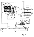
- the system comprises a positive pressure reducer 10 of known type, fed by a pipe 12 connected to a tank (not shown) containing a fuel gas such as methane, L.P.G. or biogas.
- the pipe 12 can contain a solenoid valve 13, preferably controlled by the control unit, to enable the tank to be shut off.
- the pressure reducer 10 is provided with an inlet 14 and an outlet 16 for the water circulated through it to regulate the gas temperature, so that the fuel gas leaving the pressure reducer via the pipe 18 is at constant temperature and pressure independently of the feed pressure.
- the arrows 20 and 22 indicate the direction of the gas fed to the reducer 10 and the direction of the gas leaving it respectively.
- the fuel gas which is now at a lower pressure than that which it had in the tank, is fed via the pipe 18 and the cut-off valve 104 (described hereinafter) to the proportioning actuator 28.
- This latter in the specific case illustrated, has two substantially different sized ports 30 and 32 provided in its body, both ports communicating with the pipe 18.
- a needle 34 and 36 respectively, of appropriate dimensions, can be inserted into each port 30, 32.
- the smaller port 32 and relative needle 36 enable the engine to be controlled for low loads, whereas the larger port 30 and relative needle 34 enable the engine to be controlled for high loads.
- each needle 34, 36 varies along its length, to decrease towards its free end.
- an ogival profile has been chosen for the needles.
- Each needle can be moved coaxially to the relative port by a stepping motor, 38 and 40 respectively, operable by the control unit (not shown) on the basis of the engine operating conditions measured by said conventional operation sensors (in particular the throttle valve position sensor, the engine r.p.m. sensor, the lambda sensor, and the manifold pressure sensor).
- the control unit it is therefore possible to define in the most appropriate manner the fuel quantity injected into the manifold branches, so as to achieve an air/gas mixture ratio which is as close as possible to stoichiometric.
- the most convenient profile for the needles 34 and 36 can be determined as a result of experimental tests carried out on the specific engine. As already stated, in the specific case illustrated, an ogival profile is used for the needles 34 and 36.
- the gas passing through the ports 30 and 32 emerges from the proportioning actuator 28 through the aperture 42, this latter communicating with the delivery duct 44.
- the gas flows through this latter in the direction of the arrows 46, to be fed to the single-membrane pressure regulator 148 to enter a first overall cylindrical circular chamber 150 connected to the duct 44 and separated from a second chamber 152 by an elastic membrane 154 carrying an enlargement 156 which acts as a valving element for a gas exit aperture 158, to close it when the membrane 154 is in its undeformed state (as in Figure 1).
- the second chamber 152 has the same lower diameter as the chamber 150 and communicates with the outside via a hole 172 provided in the casing of the pressure regulator 148.
- the gas exit aperture 158 communicates with the duct 60, which in Figure 1 is shown as a single duct for simplicity, whereas in reality it branches into a number of ducts equal to the number of cylinders, each of these ducts terminating in a respective injector 62 which injects the gas into a relative branch of the induction manifold 76.
- the purpose of the pressure regulator 148 (which represents the aforesaid second means) is to ensure that the gas delivery pressure is close to atmospheric pressure in the first chamber 150 of the pressure regulator 148 and in the duct 44, and that this delivery pressure depends on the pressure in the manifold 76. Moreover, under these conditions any pressure variation in the manifold 76 influences the position of the valving element 156, in the sense that if vacuum decreases (ie the absolute pressure increases) in the manifold 76 so that the valving element 156 withdraws from the exit aperture 158, the gas passage area increases, and vice versa if the absolute pressure in the manifold 76 decreases.
- the pressure regulator 148 In the body of the pressure regulator 148 there is provided a hole 160 of considerably smaller size than the cross-section of the delivery duct 44, this enabling the delivery duct to be directly connected to the induction manifold 76 via the pipe 60. This prevents sudden interruption of gas feed from the cut-off valve to the engine during re-acceleration
- a pressure regulator such as the regulator 148 can be provided for each cylinder.
- the delivery duct 44 is divided into a number of branches equal to the number of cylinders, each branch terminating in a relative pressure regulator. This latter can conveniently be located directly on the corresponding manifold 76 to also act as an injector (so that the injector 62 will no longer be required).
- Said third means consist of a so-called cut-off valve indicated overall by 104.
- the valve 104 allows proper management of sudden accelerator release and of closure of fuel gas feed to the engine.
- the valve 104 comprises a first chamber 106 connected to the gas feed pipe 18 via an aperture 108 (shown dashed in the figure) provided in the body of the valve 104.
- the first chamber 106 is separated from a second chamber 110 by an elastic membrane 112 on which a spring 114 acts to maintain the membrane 112 normally pressing against a mouth 116 to close it, this latter communicating with the feed inlet of the proportioning actuator 28.
- a hole 118 is provided in the membrane 112.
- a by-pass 120 connects the second chamber 110 to the mouth 116.
- a solenoid valve 122 closes the by-pass 120.
- this handles sudden accelerator release (ie the so-called cut-off).
- the control unit acts on the solenoid valve 122 to close the by-pass and interrupt gas flow to the proportioning actuator 28.
- the first chamber 106 of the cut-off valve there is gas present which passes into the second chamber 110 via the hole 118. Consequently after a few moments the gas in the second chamber 110 attains the same pressure as the first chamber, so that the membrane 112, which was deformed to allow gas to pass through the outlet 116, returns to its undeformed position to close the outlet 116.
- the cut-off valve 104 also handles feed shut-off when the engine is switched off. In this respect when the engine is switched off, the solenoid valve 122 closes. Hence by virtue of the hole 118 in the membrane 112 there is pressure equilibrium between the first chamber 106 and the second chamber 110 of the cut-off valve, so that the membrane 112 is in its undeformed position and closes the outlet 116.
- the control unit opens the solenoid valve 122, to hence connect the second chamber 110 of the cut-off valve 104 to the outlet 116.
- the pressure in the second chamber 110 consequently falls below that in the first chamber 106, so that the membrane 112 deforms to overcome the spring 113 and enable gas to be fed to the proportioning actuator 28.
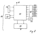
- control unit for the device is of conventional type, being substantially similar to those for petrol operation and will therefore not be described in detail.
- This control unit is shown schematically in Figure 2, in which it is indicated overall by 129, and comprises a microprocessor 130 connected to a filter stage 131 for the input signals 132A-G, to a non-volatile memory (EEPROM) 133, to an interface 134, to a gas-petrol change-over switch 135, to a power supply 137 and to an output gate 136.
- EEPROM non-volatile memory
- the microprocessor 130 is arranged to generate at the output gate the signals used for controlling the motors 38, 40 and the solenoid valves 13, 122.
- the signals fed to the output gate 136 are generated on the basis of the input signals 132A-G.
- the input signals are a signal 132A relative to the pressure within the engine induction manifolds (for this purpose a usual pressure sensor is provided in the manifold 76), a signal 132B relative to the engine r.p.m.
- the engine speed indicator signal can be used for this purpose
- a signal 132C relative to the carburation stoichiometry the signal sensed by a lambda probe can be used for this purpose
- a signal 132D relative to the position of the throttle valve this is also a signal already generally available in motor vehicles.
- the microprocessor can also advantageously receive an input signal 132E relative to the external air temperature, a signal 132F relative to the reducer exit gas temperature, and a signal 132G relative to the petrol injector adjustment.
- the input signals are fed to a conventional filter stage 131 the purpose of which is to eliminate the undesirable components of the various signals.
- the microprocessor can be connected to a usual external personal computer to which information can be fed relative to the state of operation of the gas system and from which commands can be received for setting the various control parameters.
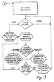
- the microprocessor 130 is schematically illustrated in Figure 3, and is of type substantially similar to that of the control unit microprocessors of petrol engine injection control systems.
- the microprocessor utilizes a mapping system with self-learning, the map variables being the pressure within the induction manifolds and the engine r.p.m. On the basis of the current pressure and r.p.m. values, the map gives the control signal for the motors 38, 40.
- the operations carried out during the microprocessor operating cycle comprise firstly the acquisition of the signals originating from the various sensors, this acquisition not being limited to merely reading the values provided by the analog-digital converter, but also implying signal filtering software.
- the execution of input signal filtering software programs is necessary because downstream of the filtering hardware section the signal can have noise components located within the filter pass band.
- the current engine operating conditions are then evaluated, ie whether the engine operating parameters are virtually identical to those evaluated within the preceding cycle (stationary operating conditions) or whether they are varying (transient conditions).
- the carburation correction is implemented in closed loop, by evaluating the signal from the lambda probe as the feedback signal and updating the map memorized in a RAM memory.
- the system is controlled in open loop on the basis of the values previously memorized in the map.
- the routine for passing to gas operation in the scheme of Figure 3 comprises opening the valve 13, positioning the motors in accordance with the value memorized in the map for the current r.p.m., opening the valve 122 and closing the petrol circuit.
- control unit 129 can be a unit independent of that for petrol operation or can be integrated into this latter in a manner conventional to the expert of the art.
Landscapes
- Engineering & Computer Science (AREA)
- Chemical & Material Sciences (AREA)
- Oil, Petroleum & Natural Gas (AREA)
- Combustion & Propulsion (AREA)
- Mechanical Engineering (AREA)
- General Engineering & Computer Science (AREA)
- Chemical Kinetics & Catalysis (AREA)
- General Chemical & Material Sciences (AREA)
- Output Control And Ontrol Of Special Type Engine (AREA)
Applications Claiming Priority (2)
| Application Number | Priority Date | Filing Date | Title |
|---|---|---|---|
| ITMI982167 | 1998-10-08 | ||
| IT1998MI002167A IT1302629B1 (it) | 1998-10-08 | 1998-10-08 | Impianto di alimentazione, attuazione e controllo di un motore ascoppio alimentato ad iniezione di gas. |
Publications (2)
| Publication Number | Publication Date |
|---|---|
| EP0992673A2 true EP0992673A2 (fr) | 2000-04-12 |
| EP0992673A3 EP0992673A3 (fr) | 2000-11-22 |
Family
ID=11380836
Family Applications (1)
| Application Number | Title | Priority Date | Filing Date |
|---|---|---|---|
| EP99104454A Withdrawn EP0992673A3 (fr) | 1998-10-08 | 1999-03-05 | Système d'alimentation et de contrôle pour moteur à combustion interne alimenté en gaz |
Country Status (2)
| Country | Link |
|---|---|
| EP (1) | EP0992673A3 (fr) |
| IT (1) | IT1302629B1 (fr) |
Cited By (1)
| Publication number | Priority date | Publication date | Assignee | Title |
|---|---|---|---|---|
| WO2025098809A1 (fr) * | 2023-11-10 | 2025-05-15 | Robert Bosch Gmbh | Dispositif de régulation de pression pour un système d'alimentation en carburant pour alimenter un moteur à combustion interne en carburant gazeux, et système d'alimentation en carburant |
Family Cites Families (7)
| Publication number | Priority date | Publication date | Assignee | Title |
|---|---|---|---|---|
| US4505249A (en) * | 1984-04-30 | 1985-03-19 | Emco Wheaton International Limited | Fuel control system for gaseous fueled engines |
| CA1326794C (fr) * | 1989-09-29 | 1994-02-08 | Ortech Corporation | Systeme de regulation du debit |
| DE59004697D1 (de) * | 1990-04-28 | 1994-03-31 | Bb Srl | Regulierungsanlage mit Rückeinwirkung des Titers des Luft-Kraftstoffgemisches zur Speisung eines Verbrennungsmotors, insbesondere eines mit gasförmigem Brennstoff gespeisten Motors. |
| US5337722A (en) * | 1992-04-16 | 1994-08-16 | Yamaha Hatsudoki Kabushiki Kaisha | Fuel control and feed system for gas fueled engine |
| JP3260506B2 (ja) * | 1993-08-31 | 2002-02-25 | ヤマハ発動機株式会社 | ガス燃料エンジンの混合気形成装置 |
| JPH0821311A (ja) * | 1994-06-30 | 1996-01-23 | Suzuki Motor Corp | 気体燃料供給装置 |
| US5692478A (en) * | 1996-05-07 | 1997-12-02 | Hitachi America, Ltd., Research And Development Division | Fuel control system for a gaseous fuel internal combustion engine with improved fuel metering and mixing means |
-
1998
- 1998-10-08 IT IT1998MI002167A patent/IT1302629B1/it active IP Right Grant
-
1999
- 1999-03-05 EP EP99104454A patent/EP0992673A3/fr not_active Withdrawn
Non-Patent Citations (1)
| Title |
|---|
| None |
Cited By (1)
| Publication number | Priority date | Publication date | Assignee | Title |
|---|---|---|---|---|
| WO2025098809A1 (fr) * | 2023-11-10 | 2025-05-15 | Robert Bosch Gmbh | Dispositif de régulation de pression pour un système d'alimentation en carburant pour alimenter un moteur à combustion interne en carburant gazeux, et système d'alimentation en carburant |
Also Published As
| Publication number | Publication date |
|---|---|
| ITMI982167A1 (it) | 2000-04-08 |
| EP0992673A3 (fr) | 2000-11-22 |
| IT1302629B1 (it) | 2000-09-29 |
Similar Documents
| Publication | Publication Date | Title |
|---|---|---|
| US3942493A (en) | Fuel metering system | |
| US6101986A (en) | Method for a controlled transition between operating modes of a dual fuel engine | |
| US5595163A (en) | Apparatus and method for controlling the fuel supply of a gas-fueled engine | |
| US5692478A (en) | Fuel control system for a gaseous fuel internal combustion engine with improved fuel metering and mixing means | |
| US4495921A (en) | Electronic control system for an internal combustion engine controlling air/fuel ratio depending on atmospheric air pressure | |
| US4416239A (en) | Electronic control system for an internal combustion engine with correction means for correcting value determined by the control system with reference to atmospheric air pressure | |
| US5136517A (en) | Method and apparatus for inferring barometric pressure surrounding an internal combustion engine | |
| JPS57108431A (en) | Control device of output from internal combustion engine | |
| US4513728A (en) | Air/fuel induction system for spark ignition internal combustion engines, and electromagnetic valves | |
| GB1563500A (en) | Fuel/air mixture supply systems | |
| US5460137A (en) | Apparatus for the temporary storage and controlled feeding of volatile fuel components to an internal combustion engine | |
| US4083338A (en) | Apparatus for controlling the fuel-air mixture of an internal combustion engine | |
| US4895125A (en) | Apparatus for the feedback of exhaust gases in an internal combustion engine | |
| JPH02277919A (ja) | 多気筒エンジンの吸気装置 | |
| EP0980467B1 (fr) | Technique permettant de determiner la valeur energetique d'un carburant fourni a un moteur | |
| GB2107394A (en) | I c engine fuel injection installation | |
| US4193384A (en) | Fuel injection system | |
| US6805091B2 (en) | Method for determining the fuel content of the regeneration gas in an internal combustion engine comprising direct fuel-injection with shift operation | |
| EP0992673A2 (fr) | Système d'alimentation et de contrôle pour moteur à combustion interne alimenté en gaz | |
| US4125100A (en) | Method and apparatus for controlling the operating mixture supplied to an internal combustion engine | |
| US3942496A (en) | Fuel injection system | |
| US4326487A (en) | Fuel injection system | |
| JP3194619B2 (ja) | 6bガス用副室式ガス機関 | |
| US4354472A (en) | Fuel injection system | |
| US6883501B2 (en) | Throttle and fuel injector assembly |
Legal Events
| Date | Code | Title | Description |
|---|---|---|---|
| PUAI | Public reference made under article 153(3) epc to a published international application that has entered the european phase |
Free format text: ORIGINAL CODE: 0009012 |
|
| AK | Designated contracting states |
Kind code of ref document: A2 Designated state(s): AT BE CH DE DK ES FI FR GB GR IE IT LI LU NL PT SE |
|
| AX | Request for extension of the european patent |
Free format text: AL;LT;LV;MK;RO;SI |
|
| PUAL | Search report despatched |
Free format text: ORIGINAL CODE: 0009013 |
|
| AK | Designated contracting states |
Kind code of ref document: A3 Designated state(s): AT BE CH CY DE DK ES FI FR GB GR IE IT LI LU MC NL PT SE |
|
| AX | Request for extension of the european patent |
Free format text: AL;LT;LV;MK;RO;SI |
|
| 17P | Request for examination filed |
Effective date: 20001213 |
|
| AKX | Designation fees paid |
Free format text: AT BE CH DE DK ES FI FR GB GR IE IT LI LU NL PT SE |
|
| AXX | Extension fees paid |
Free format text: LT PAYMENT 20001213;LV PAYMENT 20001213;MK PAYMENT 20001213;RO PAYMENT 20001213;SI PAYMENT 20001213 |
|
| GRAH | Despatch of communication of intention to grant a patent |
Free format text: ORIGINAL CODE: EPIDOS IGRA |
|
| STAA | Information on the status of an ep patent application or granted ep patent |
Free format text: STATUS: THE APPLICATION IS DEEMED TO BE WITHDRAWN |
|
| 18D | Application deemed to be withdrawn |
Effective date: 20030621 |