EP0992899A2 - Outil de programmation de tables - Google Patents
Outil de programmation de tables Download PDFInfo
- Publication number
- EP0992899A2 EP0992899A2 EP99307805A EP99307805A EP0992899A2 EP 0992899 A2 EP0992899 A2 EP 0992899A2 EP 99307805 A EP99307805 A EP 99307805A EP 99307805 A EP99307805 A EP 99307805A EP 0992899 A2 EP0992899 A2 EP 0992899A2
- Authority
- EP
- European Patent Office
- Prior art keywords
- program
- tool
- programming
- computing device
- tables
- Prior art date
- Legal status (The legal status is an assumption and is not a legal conclusion. Google has not performed a legal analysis and makes no representation as to the accuracy of the status listed.)
- Ceased
Links
Images


Classifications
-
- G—PHYSICS
- G06—COMPUTING OR CALCULATING; COUNTING
- G06F—ELECTRIC DIGITAL DATA PROCESSING
- G06F8/00—Arrangements for software engineering
- G06F8/40—Transformation of program code
- G06F8/41—Compilation
-
- G—PHYSICS
- G06—COMPUTING OR CALCULATING; COUNTING
- G06F—ELECTRIC DIGITAL DATA PROCESSING
- G06F8/00—Arrangements for software engineering
- G06F8/30—Creation or generation of source code
- G06F8/33—Intelligent editors
-
- G—PHYSICS
- G06—COMPUTING OR CALCULATING; COUNTING
- G06F—ELECTRIC DIGITAL DATA PROCESSING
- G06F9/00—Arrangements for program control, e.g. control units
- G06F9/06—Arrangements for program control, e.g. control units using stored programs, i.e. using an internal store of processing equipment to receive or retain programs
- G06F9/44—Arrangements for executing specific programs
- G06F9/448—Execution paradigms, e.g. implementations of programming paradigms
- G06F9/4498—Finite state machines
Definitions
- the present invention relates to a programming tool.
- a programming tool using different kinds of tables to achieve a programming function and to facilitate control of program flow.
- the programming tool of the present invention makes extensive use of tables to enable a programming process to be easily understood by third parties.
- the improvements provided enhance the efficiency of programming and reduce the likelihood of the presence of program bugs or structural errors.
- the cost of training required for a programmer to learn the programming method is minimal.
- the resulting programs composed with the invented tool also are easy to read and to be maintained by any programmer.
- coding symbols and instruction set are designed to describe programming functions. Rules are also designed to restrict how the programming instructions are to be used in order to make a program written with the language interpretable and executable by a computing device.
- the instruction manual describing a programming language is over two inches thick in order to document all these instruction sets and describe the programming rules. It is not unusual for months of training effort to be required in order for a programmer to learn the whole instruction set and understand all the programming rules of a new programming language. More programming tricks are usually learned through subsequent years of programming experience.
- the present invention is directed to the inventive steps of providing the architecture of a generic model to program a computing device making use of the concept of table format programming.
- One objective of the invention is to structure the generic model such that it is simple enough to be applied by ordinary people without receiving intensive professional training.
- a further objective is to establish a programming model such that any program written with this format can be easily understood by another person without having extensive experience in the language or close involvement with the writing of the program.
- Another objective of the invention is to establish a programming model that clearly identifies the structure of a programming job through the coding process, therefore enabling the program to be maintained with minimal effort.
- Another further objective of the invention is to establish a structural programming format which is able to express a clear skeletal structure of the job while enabling the individual specific functional program modules to be selectably programmed with any language most suitable for that function. This approach further enhances the efficiency of programming and reduces the amount of future maintenance work required.
- the programming method of the present invention comprises the steps of filling up two or more tables with program data.
- Various types of tables are designed to perform different supporting functions.
- a table is defined as a matrix of data.
- a table may have one or more dimensions.
- a table matrix is typically represented by m row and n columns where m and n are integers equal to or greater than one.
- Each element of the table may be represented by a label, a single expression or a sequence of expressions.
- the programming method uses the concept of a task table which comprises a table of data formed to control the activity of multiple tasks. More than one task table may be present in a program, each table comprising one or more task states. Whenever a task state is specified in the programming process, the situation and/or activities of the tasks specified are defined. Further task priority information may be included in the activity task table or provided in another separate table for the computing device to assign or handle priority while running multiple tasks with the shared resources of the computing device.
- a table is formed to define one or more configuration states which may include input and/or output information.
- an input qualifying condition of a configuration state When an input qualifying condition of a configuration state is satisfied, it will cause a response of a specific sequence of actions represented in another table called an event table or path table.
- At least one configuration state is to be specified as the active state.
- a further table is formed to define the qualifying conditions required to trigger a qualifier configuration state.
- the concept of virtual qualifier is first introduced.
- a virtual qualifier is defined as any qualifying condition not coming from a physical hardware terminal.
- Virtual qualifier is important as it includes the consideration of a result which comes from a single software instruction or from a whole software program.
- Virtual qualifier may also include hardware internal to a computing device such as overflow of an internal register. It may be triggered by the result of an internal software or hardware interrupt, generation of a sign, polarity signal, signal indicating the presence of data from another system or the presence of a flag.
- Another commonly used example of virtual qualifier is the output of a mouse driver program which specifies the direction of motion of a pointer according to the movement of a mouse.
- a table is formed to define the output configuration of an output state.
- the output state may be a signal to be sent out through a physical hardware terminal or the configuration of a virtual computing output state.
- a virtual computing output state is defined to be any output state which does not describe the activity of a hardware terminal.
- An example of a virtual computing output state is the triggering of a software program to start running, or to set particular conditional parameters to control software, or for the software to perform some specific function.
- a path table or event table is a table grouping one or more responsive actions.
- a path may represent an action or a sequence of actions to be performed when a qualified condition is received.
- a path may be initiated by another path.
- This responsive action or sequence of actions is named a path equation.
- the interactive composition of state tables and the path table is analogous to event structure illustrated with state diagrams.
- table format programming offers a program presentation which is more user-friendly.
- each path in the path table can be assigned a meaningful label according to the wish of the programmer.
- a meaningfully named label can be assigned to a configuration state or a path. All these labels help the programmer or other people understand the action and logic flow of the written program. This is an important contribution of the present invention to help interpret a composed program and reduce future maintenance costs.
- Another table which can be included in the invented programming process directs an output condition in an output state to a specific sequence of operation. This sequence can be represented by another table to simplify the programming process.
- a further type of table introduced in the present invention enables the programmer to change the expression and/or syntax of the table format programming language into any other expressions or symbols desired.
- Further tables which may be included define one or more sets of library or external programs required to support the programming job.
- the programmer interactively describes the skeletal structure of the program flow with tables of states and paths.
- the programmer is free to assign meaningful labels or names to represent each configuration state and path.
- the meaningful names of each state configuration and path equation help to describe the flow of the program.
- the programmer is free to assign a meaningful label to represent this desired action.
- the programmer should furnish executable program modules or expressions for each of the undefined labels assigned. In this way program modules are formed by interactively organizing multiple groups of tables.
- a program module having at least a state table and a path table is named a program group or table group.
- Each program group can be assigned another meaningful label to describe the function of the program module. This label can then be utilized in another program module or group for pointing to this program group when a jump or function call is required.
- the very first program group to be executed when the program is started by default is named the "main” group for convenience. Inside each group, there should be a "start" up path to serve as the starting path when the program is initialized or starts from default.
- supporting program modules may be composed with a desirable language different from the language of the table format programming method used in the main group. Many different languages may be utilized in the same program.
- a table format program is designed to interface with different programming languages and to serve as a bridge to communicate between program modules written in different languages.
- the program eventually composed can then be compiled or translated into a specific desired programming language, including Assembly Language or even machine code digital data.
- the table format programming language significantly changes the concept and practice of writing a program.
- a program is written in a logical and well-structured manner. By making use of the freedom to assign meaningful labels, the program flow is as smooth as composing a composition to describe the programming job.
- Each label is then linked with an external program module which can be written in any language desired. From time to time, multiple levels of program groups or modules can be arranged. Because the program size of each table format group is usually quite small and the program is well structured, the aforementioned advantages of table format programming can be easily achieved.
- Freedom to assign or equate labels and instruction keywords is very important for table format programming to support a multiple languages programming platform. This is because different languages may make use of different syntax for the same kind of application.
- the freedom of labeling and equating features enables the user to unify the labels and syntax according to his/her requirements.
- table format programming makes it a perfect supporting tool to enhance the programming structure of another language.
- the compiler of a high level language can be modified to include just sufficient of the table format programming function to provide a skeletal structural of a program written in that language.
- the table format coprocessor may be a processor located outside the main processor or may coexist with the main processor within the same integrated circuit chip.
- table format programming is applied to microprocessors or micro controllers, the compiled or encoded table format program becomes digital data which is stored in memory such as ROM, EPROM or flash memory for the execution of the microprocessor or micro controller.
- a printed circuit assembly comprising the processor and memory storing the compiled representation of the table format program is then used to build up a finished commercial product for point of sale distribution.
- table format programming it is particularly suitable for event driven applications such as programming under a windows environment, web site, interactive game or control programming.
- An important characteristic of table format utilized in event driven programming is that it is a highly compressed format to represent a program. Most table format programs for small jobs are less than one page long. Experimental results demonstrate that one page in table format programming may represent eight pages of assembly language program, depending on the complexity of the available instruction set. Considerable code size saving can also be achieved when compared with many high level languages. This feature makes table format programming economical to use as a media to communicate through a limited bandwidth communication channel; such as between a host system communicating with numerous local computers in network or internet applications.
- a network, communication link or communication channel refers to any means connecting two computing devices together, including serial port, parallel port, USB port, internet, intranet, extranet, LAN, ISDN, DSL and any communication means interfacing two computing devices.
- the devices on the network may be connected by wired, wireless or mixed mode connection.
- internet programming a further step is required to evaluate the system configuration of a user computer and then adjust the program settings before a downloaded program can be executed by the local computer.
- the configuration of many computer to human interface devices such as monitor, graphic card, sound generation device, pointer control, game controller control are among the configuration settings to be defined. Because the internet communication line is usually the bottle neck of a system, it is recommended that the compiling job for table format programming is performed at the local computer level in order to make use of the advantages of the compressed codes of table format programming.
- Figure 11 is a block diagram showing how a local computer 801 is connected with a remote computer 803.
- a table format program is stored in the local computer. It is downloaded to a remote computer through a communication link 802 upon request.
- the table format program can be stored in the memory means 804 of the remote computer or immediately compiled by the remote computer.
- the compiled file is an executable file to perform some predefined work at the remote computer. This executable file can also be stored in the memory means 804 of the remote computer.
- the compiling, translating, interpreting or transforming of the table format programming method includes the process of converting the table format program into any other program format such as machine language or any higher level language.
- the conversion process can be performed by a compiler program written in another programming language or supported by an executable table format program as well.
- a debug tool may be configured to reference a particular location of the table format program and the corresponding location of the program translated into another programming language.
- a user can simply request the transmission of a data chain in a table format program. After the table format program is translated into Assembly Language, the user is able to locate the transmission process in the Assembly code listing and then modify the transmission characteristics of the UART as desired.
- This debug tool is very helpful when it is preferred to tune a particular process in the environment of another programming language.
- task table effectively extends the convenience of table format programming to a multitask environment as well.
- the definition of computing device refers to any device having computing capabilities, including computers, micro controllers, microprocessors, printed circuit assemblies comprising micro controllers or microprocessors.
- other supporting hardware required to support the invented technology are the debugging hardware, communication links such as cables, communications ports, hubs and networks as defined in the specification.
- the table format program may be displayed on display terminals, printed on printers, and encoded as digital data.
- the encoded digital data representing the table format program may be stored in any memory device such as RAM, ROM, disk drive, and CD ROM.
- pre-programming activities involve the analysis of the program job specification and the reduction of the project into a table format coherent state diagram.
- table format program groups while enhancing the clarity of program structure, requires the user clearly to identify and define the specific functional modules of the project before starting to apply the programming technology.
- another interface specification procedure is required to document the interfacing relationship of table format programming groups or modules in order to allocate the programming job to a team of programmers.
- the pre-computer activities involve sending the table format program to a remote computer through a communication link or network.
- the in-process computer activity is performed by the table format compiler which translates the table format program into codes executable by a local computer, a target microcontroller, or a remote computer.
- the post-computer activity is usually a code executable by the target computer or microcontroller.
- This executable code can be further run by the computer or microcontroller to perform the function according to the original programming specification.
- the compiled executable code is usually stored in memory means defined by RAM, ROM, any programmable no-volatile memory or any other storage devices commercially available.
- the memory means storing the compiled executable file is usually located in the article of sale rather than in the compiling computer. In this situation, the compiling computer simply acts as a development system or a program supplier for a remote computing device.
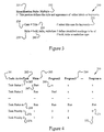
- Figure 1 illustrates the structure of an embodiment of a table format program.
- Figure 2A is a table defining the table format expressions to be equated to user defined expressions.
- Figure 2B demonstrated how a name is assigned to the table of Figure 2A.
- Figure 3 is a table formed to define different printing styles of words to be identified.
- Figure 4 is an embodiment showing different task states of a task table.
- Figure 5A is an embodiment showing multiple task tables in a program.
- Figure 5B is a numbered representation of Figure 5A.
- Figure 6A is a program showing an embodiment of a table format program group.
- Figure 6B is a further development of the embodiment of Figure 6A.
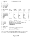
- Figure 7 is a table showing a list of files to be included.
- Figure 8 is a further development of the table of Figure 7.
- Figure 9 demonstrates some proposed lengthy and descriptive instruction commands to be used in table format programming.
- Figure 10 demonstrates a prior art fundamental table format program suitable for use in voice generating microcontrollers.
- Figure 11 is a block diagram showing a local computer downloading a table format program to a remote computer through a communication link.
- the initial attention is directed to Figure 10 for a review of fundamental table format programming disclosed in issued US Patent 5,867,818.
- the table format program consists of two parts, a state table and a path table to program a sound generating programmable controller.
- the order of the corresponding input trigger pins of the controllers is defined.
- Each of StateO to State 4 defines a possible trigger state of the controller.
- the R:Pathl element corresponds to TG1 of StateO indicates that if a rising edge (represented by "R") is detected, the path named Path1 is executed.
- Pathl the active state is changed to Statel, then a sound named "Soundl" is generated.
- Figure 1 depicts the structure of a table selected in an embodiment of an improved table format program.
- the keyword 101 indicates the start of a program.
- the name of the program can be assigned by the programmer in a position next to the keyword.
- Keyword 106 indicates the start of a table listing program modules to be included.
- Keyword 107 indicates the start of a table defining constants to be used in the program.
- Keyword 102 declares the variables to be used in the program.
- Keyword 103 is a table listing the user-defined equivalents of commands and syntax expressions.
- the programmer may define the keyword printing style in a table starting with keyword 104. All the above features provide the preparation work of the table format program.
- the task table 105 provides one or more task states to define which tasks are to be activated, paused or terminated.
- Program group 111 comprises an optional qualifier table 112, at least one state table 113 and one path table 116.
- the actual program job involves interactively composing the content of the state table and the path table.
- Additional output state table 115 and output equation table 114 can be added to further define the output state(s) of the program.
- a library table 121 can be added to furnish commonly used command strings and routines. It should be noted that all the tables described above are not required to be listed in sequential order and many tables may be established to provide optional features.
- a program may contain multiple tables of a similar type as in the situation of the task tables and the state tables.
- Names of the tables can be freely assigned following the colon sign of the keywords to better present the meaning of the program. Keywords used in table format programming may have more than one word and may refer to instructions, specific variables, constants and hardware elements of the system. It should be noted that the keywords provided are exemplary and alternative names of keywords can be used. Besides, some reasonable variation of the scope of the tables is always possible and is considered to be within the scope claimed in this application.
- the table 200 represents a detailed example of the table 103 of Figure 1.
- the keyword 201 "Custom Expression" represents the start of this functional table which lists the user-defined equivalents of official table format expressions. For example, assuming an official table format expression for the logical AND function is "AND" of 203; a programmer who prefers C language programming is free to substitute the table format command "AND" by "&&", 202 as used by the C language instruction set. Custom expressions are applicable to any word or symbol set used by the language or system, such as instruction commands, symbols and system keywords. It is recommended that a comment 204 is provided every time an alternative expression is defined. The advantage of this function is to provide a personalized support to the programmer so that familiar notations or expressions can always be used.
- the compiler or editor when the composed program is printed, it is preferable for the compiler or editor to print out the program listing with the official expressions so as to facilitate the reading of the program listing by other people.
- a similar application concept can be extended to a program editor.
- the official expression can be displayed as soon as the user-defined expression is keyed in.
- a switching function between the predetermined official and user-defined expressions is also recommended, so the user can have a choice of the program being displayed or printed in the official form or custom form.
- meaningful lengthy expression names can be used to make the program listing more readable by other people while keeping the advantage for the programmer of using abbreviated expressions or short length symbols to represent instruction commands and syntax.
- Groups of official syntax and the corresponding group of user-defined equivalent syntax and labels can be built in the table format program with the commonly known table look up method.
- a typical application example is illustrated in Figure 9, where some lengthy and descriptive instruction set is shown.
- the shift operators "BIT SHIFT LEFT” and “BIT SHIFT RIGHT” clearly describe the operation to be performed. However, these instructions are too long and not welcome by skilled programmers.
- the programmer may then equate the "BIT SHIFT LEFT” instruction to the concise but less descriptive " ⁇ ” instruction used in the C language.
- the long instruction names make the program easily understood but too clumsy for skilled programmers.
- the "Custom Expression” table effectively resolves this concern while maintaining the advantages of the long instruction expressions.
- the custom expression table provides a way to ease this problem by enabling users to reconfigure instructions and symbols according to their preference.
- Element 210 illustrates how a name "MySign” is assigned to the "Customer Expression” table.
- a name is required particularly when more than one set of “Customer Expression” tables are provided to enable more than one user to manipulate or read the program.
- another custom table named as “JohnsSign” can be added in the same program. If John wants to read the program, he simply sets the "JohnsSign” expression table as the default displaying table, and John will see the program displayed in his favored format.
- the novel feature of this table is to enable every user to include their own set of custom defined expressions so as to facilitate converting or editing the program in their preferred format.
- Figure 2A provides a method to reconfigure keywords and expressions, it is desirable to have a simple method to provide alternative expression or commands of another language for a small job. This can be achieved by specifying a symbol representing a specific language in front of expressions specified by that language.
- Figure 2B illustrates how the content of Register A is to be masked with the binary number 00001111 so as to obtain the last four bits of the Register A content, and then proceed to display this number.
- the expression 216 provides the element "(C:&&)" to indicate that the "&&" instruction is an instruction of the "C" language.
- the masked value of Register A is then displayed using a predefined "Display" command.
- an expression performing the same function may be obtained by using the "&" instruction of the assembly language of a microprocessor.
- the sign “A: ( )” is an expression to indicate the operation included in the brackets is written in assembly language.
- Figure 3 demonstrates a table of the program which controls how the user-assigned labels are to be presented.
- the table element 234 provides the selection of case. Typical cases available for selection are title case, all upper case and all lower case.
- the table element 239 indicates the choice of the letter style. Typical choices available are bold, italic and underline.
- Keyword 231 indicates the start of the identification style definition section of the program. It is recommended that a user-assigned name is placed after the keyword 231 to indicate that the following setting is the preferred setting of a particular person.
- Multiple identification style tables assigned according to the preference of different people can be included in the program and each table assigned a name as represented by element 232. A selection of one of the identification style tables as active, sets the printing style to suit the preference of the particular user reading the program.
- a task control table (hereafter referred to as a task table) is introduced in the embodiment demonstrated in Figure 4.
- Element 261 is a keyword to identify a task table.
- Element 262 is a label assigned to name the task table. This name is provided in order to differentiate from other task tables if two or more task tables are required.
- Elements 263, 264 represent different tasks or programs which may be run under the control of the task table.
- Each row 265, 268 of the table represents a task state. In each task state a task condition is assigned to represent the condition of each task. Listed below are some examples of expressions to describe a task condition:
- the task "Task Status 1" instructs the "Main" program to start running while programs 2 to n are in terminated condition.
- the task state 268 all the programs are instructed to run. It should be noted that for each task table, only one task state is active at a time. In systems with limited resources, it is important to assign priority to the active task running.
- the task states 273 and 274 assign priority to the tasks. It should be noted that a separate table can be established just to describe priority assigned to the tasks. Because the title elements of each element of the activity task table and priority task table are identical, it is possible to combine the two types of task tables into one as shown in Figure 4. In this situation, two active task states are required, one for the task activity status and one for the task priority assignment.
- Figure 5A illustrates a real world application example to demonstrate the concept of the task table.
- Figure 5B is a numbered illustration of Figure 5A.
- This example comprises three task tables.
- the first task table is named as "Input” as shown in element 301. It comprises three programs named “Keyboard” 302, "Mouse” 303 and "Gameport” 304.
- "Keyboard” is a program scanning the keys of a keyboard.
- “Mouse” is a program decoding the motion of a mouse while "GamePort” inputs the trigger signals obtained from a game port.
- the task state 305 named “All”
- all the three programs are running to enable the computing device to be responsive to all three input devices.
- the task state 306 named "Normal" only the keyboard and mouse are enabled.
- the game port is not used so as to improve the servicing efficiency of the computing device.
- the task state 309 named "Game” becomes the only active program or task.
- the keyboard and mouse are not used so as to let the computing device focus all its resources on servicing the game play.
- the second task table is a table named "Ports” 321 which controls the serial and parallel ports of the computing device.
- the third task table is named "Device”, as shown in element 341. It controls the driver programs to operate the "CDRom” 342, the “HardDriveC” 343, and the floppy disk drive.
- the task state "ReadCD" 345 is activated, the CD Rom and the Hard Drive C driver programs are activated but the floppy disc driver program is terminated.
- the task state "HDFullSpeed" 346 becomes the active task state where the hard drive becomes the only running device. According to this application example, it is recommended to group only similar nature or interrelated tasks to form a common task table. It should be noted that only one task state from each task table is to be assigned to be active at any time.
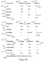
- FIG. 6A a main group of table format program is demonstrated.
- the program is named as "WebSale” which provides a skeleton structure of a sales program to be provided through the internet.
- WebSale provides a skeleton structure of a sales program to be provided through the internet.
- This example illustrates the concept of multiple language programming in the table format programming environment.
- the line numbers of the program are only inserted to facilitate the description of the embodiment. It should be noted that the states and path equations are not required to be in sequence. Attention is now drawn to line 1.
- a keyword “Group” indicates the starting of a table format group or program module.
- the name of the group is "Main”.
- Main is assigned as a keyword to indicate that this group is the first group of programs to be executed when the program starts to run.
- Line 2 starts with a keyword "qualifier” which defines the qualified conditions of the qualifiers listed in a configuration state.
- the term “Icon” applies to a functional command which constructs an icon and provides a trigger to the configuration state when this icon is clicked.
- Icon In a typical arrangement of table format programming icons are numbered serially. Each icon is defined and named in the qualifier table. As an example, when Icon(1) is equated to the name “Catalog”, the word “Catalog” is assigned and displayed to the first icon. In fact, once a name is assigned to an icon, the number it carries is immaterial unless the term “icon(n)" is mentioned in a program and "n” is a result of a computation.
- Line 8 defines an input states configuration table named "FirstPage". There are five qualifiers assigned in this table namely "Catalog”, “Purchase”, “Service”, “Home” and “Quit”. Each qualifier refers to the trigger of an icon as defined in the qualifier table of line 2.
- the first input qualifier state is named “Ready” as in line 9. In this state, when a qualified trigger representing the icon "Catalog” is received, the path named “P_catalog” is executed and similarly for the other qualifiers.
- the other input configuration state is named "Hold1" as indicated in line 10.
- An "x" in the state equation indicates that the corresponding qualifying condition is in a "don't care” condition, for which a trigger is blocked or no response is required when a qualified trigger comes in.
- the last element of the output configuration is a hardware port P3.1 which connects to a speaker of the computing device. When a code P+ is assigned to this port, a burst of positive going pulses is sent to the speaker and a beep tone is heard.
- Port P3.1 is a hardware terminal and is therefore classified as an hardware oriented output. All the first four groups are software oriented output conditions and are classified as virtual computing outputs. Any output condition not related to a hardware output terminal is defined as a virtual computing output The definition of virtual computing output includes any non-terminal related activity which generates data, displays or produces signals or information, initiates a program, resets a program, starts a software timer or counter, or manipulates an internal circuitry such as a register etc.
- Lines 12 to 17 are the output states configured under the state table "Response". When a "Run " command appears in an output configuration state, the corresponding group program is run. When a "Continue" instruction is received, a running program continues to run or the program remains idle if it had not yet been started or is in a pause condition. The "x" sign indicates no output action is required. With all these descriptions, the action of the output states in lines 12 to 17 are self explanatory. It should be noted that more than one input or output state table may be present in a program. Multiple state tables simplify the structure of the tables and make the programming job easier. However, it should be noted that only one of the configuration states of every input state table should be specified to be active at a time. As a programming trick, the interrelated inputs qualifiers and output conditions can be combined to form a state table. It should also be noted that input states and output states can also be combined to form a mixed state if desired.
- Line 18 starts the action "Path(s)". Each path defines one or more actions to be executed when the path name is recited in any qualifier element of a configuration state.
- Line 19 is a path named "Start” which is the default starting path when the Group is executed.
- the programming procedure starts by reciting the desired action when the program is first started.
- the starting action “CheckSystem” checks the configuration of the local computing system such as the display drivers, physical port to drive the speaker and the system resources available to run the program.
- the resources available in the local computing devices to be evaluated include the computer time, number of registers, amount of memory available, memory configuration, timer and counters occupied, interrupt channels available and any specific hardware circuit configuration.
- the "CheckSystem” action should be a procedure to reconfigure the downloaded program according to the parameters of the system.
- the next step is to display the first page. This action is simply defined as “DisplayFirstPage” in the program. A “Beep” sound is then generated. "Hold2" indicates all output configurations are put on hold as directed by the "Response” state table.
- the "Ready” instruction initiates the “Ready” state of the input state table "FirstPage". During the "Ready” state, whenever a qualified trigger of the icons "Catalog”, “Purchase” or “Service” is received, one of the corresponding paths 20 to 22 is executed.
- the supporting programs can be written in any languages or even by another table format program. These supporting programs are then "Included” in the program for the compiler to put the programs together.
- Line 19 of Figure 6B indicates that the “CheckSystem” is preferably a program written in Java, as denoted by the prefix "EJ", where "E” means it is an external program to be included.
- the action "DisplayFirstPage” is preferably written in Visual Basic.
- the action "BuySolicit" a window to solicit purchasing is preferably derived from a local or global library.
- Line 24 indicates the starting of the local library.
- Line 25 is a further elaborated path equation which describes the action to solicit the customers.
- This action includes executing an external program "CheckRecord” written in "C” and a program named “SolicitWindow” written in Visual C++ to interactively solicit the customer to buy products.
- the element “GrayButton” in line 21 refers to a path positioned in the local library which comprises a “C” program to identify which icon is assigned an “x” and then another program written in Visual Basic to turn these icons into a gray color to indicate that these icons cannot be triggered.
- Figure 7 indicates an exemplary include table when a program involving windows and a transceiver is to be composed.
- the supporting programs in this include table are mandatory and therefore it is desirable for the compiler to outline any included program not being used in the composed program.
Landscapes
- Engineering & Computer Science (AREA)
- Software Systems (AREA)
- Theoretical Computer Science (AREA)
- General Engineering & Computer Science (AREA)
- Physics & Mathematics (AREA)
- General Physics & Mathematics (AREA)
- Stored Programmes (AREA)
Applications Claiming Priority (2)
| Application Number | Priority Date | Filing Date | Title |
|---|---|---|---|
| US16946298A | 1998-10-09 | 1998-10-09 | |
| US169462 | 1998-10-09 |
Publications (2)
| Publication Number | Publication Date |
|---|---|
| EP0992899A2 true EP0992899A2 (fr) | 2000-04-12 |
| EP0992899A3 EP0992899A3 (fr) | 2002-06-12 |
Family
ID=22615805
Family Applications (1)
| Application Number | Title | Priority Date | Filing Date |
|---|---|---|---|
| EP99307805A Ceased EP0992899A3 (fr) | 1998-10-09 | 1999-10-04 | Outil de programmation de tables |
Country Status (4)
| Country | Link |
|---|---|
| EP (1) | EP0992899A3 (fr) |
| JP (1) | JP2000148459A (fr) |
| CN (2) | CN1250907A (fr) |
| TW (1) | TW446914B (fr) |
Cited By (3)
| Publication number | Priority date | Publication date | Assignee | Title |
|---|---|---|---|---|
| EP1380944A2 (fr) * | 2002-07-12 | 2004-01-14 | Ensequence, Inc. | Procédé et système de contrôle automatique de l'apparence et de l'exécution d'une application graphique |
| CN103294478A (zh) * | 2013-06-17 | 2013-09-11 | 宁夏新航信息科技有限公司 | 一种计算机软件的智能化编程方法 |
| CN104216688A (zh) * | 2013-05-30 | 2014-12-17 | 宁夏新航信息科技有限公司 | 一种智能化的计算机软件编程方法 |
Families Citing this family (3)
| Publication number | Priority date | Publication date | Assignee | Title |
|---|---|---|---|---|
| CN106155669B (zh) * | 2015-04-18 | 2019-04-05 | 成都复晓科技有限公司 | 一种软件界面与宏语言的参数匹配方法 |
| TWI638276B (zh) * | 2017-04-28 | 2018-10-11 | 如如研創股份有限公司 | 物料表形式之結構化設計規格書產生方法 |
| CN114527712A (zh) * | 2021-11-22 | 2022-05-24 | 广东嘉腾机器人自动化有限公司 | Agv任务修改方法及修改系统 |
Family Cites Families (3)
| Publication number | Priority date | Publication date | Assignee | Title |
|---|---|---|---|---|
| US4727575A (en) * | 1985-12-23 | 1988-02-23 | American Telephone And Telegraph Company, At&T Bell Laboratories | State control for a real-time system utilizing a nonprocedural language |
| US5386464A (en) * | 1991-12-19 | 1995-01-31 | Telefonaktiebolaget L M Ericsson | Feature control system utilizing design oriented state table language |
| US5867818A (en) * | 1995-10-02 | 1999-02-02 | Lam; Peter Ar-Fu | Programmable sound synthesizer apparatus |
-
1999
- 1999-09-29 JP JP11276100A patent/JP2000148459A/ja active Pending
- 1999-10-04 EP EP99307805A patent/EP0992899A3/fr not_active Ceased
- 1999-10-07 TW TW088117272A patent/TW446914B/zh not_active IP Right Cessation
- 1999-10-08 CN CN99120898A patent/CN1250907A/zh active Pending
- 1999-10-08 CN CNA2007101264505A patent/CN101154158A/zh active Pending
Cited By (3)
| Publication number | Priority date | Publication date | Assignee | Title |
|---|---|---|---|---|
| EP1380944A2 (fr) * | 2002-07-12 | 2004-01-14 | Ensequence, Inc. | Procédé et système de contrôle automatique de l'apparence et de l'exécution d'une application graphique |
| CN104216688A (zh) * | 2013-05-30 | 2014-12-17 | 宁夏新航信息科技有限公司 | 一种智能化的计算机软件编程方法 |
| CN103294478A (zh) * | 2013-06-17 | 2013-09-11 | 宁夏新航信息科技有限公司 | 一种计算机软件的智能化编程方法 |
Also Published As
| Publication number | Publication date |
|---|---|
| CN1250907A (zh) | 2000-04-19 |
| JP2000148459A (ja) | 2000-05-30 |
| EP0992899A3 (fr) | 2002-06-12 |
| CN101154158A (zh) | 2008-04-02 |
| TW446914B (en) | 2001-07-21 |
Similar Documents
| Publication | Publication Date | Title |
|---|---|---|
| Campione et al. | The Java tutorial: a short course on the basics | |
| US7231630B2 (en) | Method and system automatic control of graphical computer application appearance and execution | |
| US20030058267A1 (en) | Multi-level selectable help items | |
| US20040036715A1 (en) | Multi-level user help | |
| KR20010005989A (ko) | 입력 방법 편집자를 버츄얼 머신에 통합하는 방법 | |
| EP0992899A2 (fr) | Outil de programmation de tables | |
| Schroeder et al. | The book of Dash: build dashboards with Python and Plotly | |
| Ma et al. | Dynex: Dynamic code synthesis with structured design exploration for accelerated exploratory programming | |
| US9063719B1 (en) | Table format programming | |
| Skansholm | Java from the Beginning | |
| Mansfield | The joy of X: an overview of the X Window system | |
| CA2304427A1 (fr) | Outil de programmation de format de tableau | |
| Savitch et al. | Problem solving with C++ | |
| US20030101165A1 (en) | User editable help items | |
| Cotton | Languages for graphic attention-handling | |
| Singer et al. | Let’s Take Esoteric Programming Languages Seriously | |
| HK1027410A (en) | Table format programming | |
| Zelle | Python programming: an introduction to computer science | |
| Gupta et al. | The first decade of personal computers | |
| Thimbleby | The design of a terminal independent package | |
| Pohl et al. | Java by dissection | |
| Beshir | Cross-platform development with React Native | |
| Padala | Ncurses programming howto | |
| Inoue | Volume II: Morphological Analysis 51 | |
| Stelzer | Marching towards a satisfactory FEM graphical user's interface |
Legal Events
| Date | Code | Title | Description |
|---|---|---|---|
| PUAI | Public reference made under article 153(3) epc to a published international application that has entered the european phase |
Free format text: ORIGINAL CODE: 0009012 |
|
| AK | Designated contracting states |
Kind code of ref document: A2 Designated state(s): AT BE CH CY DE DK ES FI FR GB GR IE IT LI LU MC NL PT SE |
|
| AX | Request for extension of the european patent |
Free format text: AL;LT;LV;MK;RO;SI |
|
| PUAL | Search report despatched |
Free format text: ORIGINAL CODE: 0009013 |
|
| AK | Designated contracting states |
Kind code of ref document: A3 Designated state(s): AT BE CH CY DE DK ES FI FR GB GR IE IT LI LU MC NL PT SE |
|
| AX | Request for extension of the european patent |
Free format text: AL;LT;LV;MK;RO;SI |
|
| 17P | Request for examination filed |
Effective date: 20021205 |
|
| AKX | Designation fees paid |
Designated state(s): AT BE CH CY DE DK ES FI FR GB GR IE IT LI LU MC NL PT SE |
|
| R17P | Request for examination filed (corrected) |
Effective date: 20021205 |
|
| 17Q | First examination report despatched |
Effective date: 20061120 |
|
| STAA | Information on the status of an ep patent application or granted ep patent |
Free format text: STATUS: THE APPLICATION HAS BEEN REFUSED |
|
| 18R | Application refused |
Effective date: 20091009 |