EP0992934A2 - Système et méthode pour manipuler des régions dans une image scannée - Google Patents
Système et méthode pour manipuler des régions dans une image scannée Download PDFInfo
- Publication number
- EP0992934A2 EP0992934A2 EP99109939A EP99109939A EP0992934A2 EP 0992934 A2 EP0992934 A2 EP 0992934A2 EP 99109939 A EP99109939 A EP 99109939A EP 99109939 A EP99109939 A EP 99109939A EP 0992934 A2 EP0992934 A2 EP 0992934A2
- Authority
- EP
- European Patent Office
- Prior art keywords
- region
- user
- regions
- scanned
- text
- Prior art date
- Legal status (The legal status is an assumption and is not a legal conclusion. Google has not performed a legal analysis and makes no representation as to the accuracy of the status listed.)
- Granted
Links
Images


Classifications
-
- G—PHYSICS
- G06—COMPUTING OR CALCULATING; COUNTING
- G06V—IMAGE OR VIDEO RECOGNITION OR UNDERSTANDING
- G06V30/00—Character recognition; Recognising digital ink; Document-oriented image-based pattern recognition
- G06V30/40—Document-oriented image-based pattern recognition
Definitions
- the present invention relates generally to electronic scanning devices, and, more particularly, to a system and method for manipulating regions in a scanned image.
- Scanning devices are useful in many applications where it is desirable to transfer an image from printed form into electronic form.
- Scanners capable of reading and converting a page into electronic format have been available for quite some time.
- a scanner will electronically read a page, classify the different types of images on the page and electronically store the information for later presentation and use.
- the types of classifications of a scanned page typically include text, photographs, drawings, charts, tables, business graphics, equations, handwriting, logos, etc . These different parts of a scanned image are typically classified into regions by a user after the scanner has scanned the page.
- Some scanners are capable of determining the classifications of particular regions of a scanned page in accordance with predetermined instructions.
- some scanners will scan the page and will classify and store the text information as a text region and will classify and store the drawing information as a drawing region, and so on.
- the scanner it is possible for the scanner to interpret some regions in a manner different from that which a user desires. Multiple interpretations of the same scanned information are possible regarding the attributes of a scanned image that should be presented to a user.
- a scanner or more properly the scanner analysis code, might classify a particular section of text (e.g ., a large capitalized first letter of a paragraph) as drawing information, or as another example, the scanner analysis code must determine whether text over a colored background should be presented as text or as part of a bitmap that includes all of the background pixels.
- These predefined classifications may be acceptable for some users of the scanner, but other users may wish to have the ability to alter, or adjust, the sensitivity of the scanner for each classified region type, or alter the manner in which the regions are grouped, or clustered.
- one user might wish only to scan a page for the purposes of entering the information on that page into a word processing document with no further manipulation desired.
- a different user may wish to scan the same page for the purposes of manipulating the information on the page in a more sophisticated manner.
- the regions are typically non adjustable.
- a primitive region is the simplest possible representation of a region. For text, therefore, a primitive is a single word. For a table a primitive is a single cell. For a business graphic a primitive is a single graphic element or a single textual element.
- a composite region is comprised of two or more region primitives.
- a text paragraph is itself comprised of text line composites, which are comprised of text word primitives.
- Tables are comprised of their cell, horizontal rule, vertical rule, column and row primitives.
- Charts, graphs and equations are comprised of combinations of text, mathematical character, rule and drawing primitives. Boxes and cartoons are comprised of drawing, text and/or handwriting primitives.
- An “enclosed” region is a region whose entire set of pixels fall within the boundary of another "containing” region.
- Important examples of enclosed/containing region combinations include text, photographs, etc., that are within containing boxes; cells within tables that have containing rules; regular or "inverse" (i.e ., lighter) text over a photograph or drawing; text on business graphics; and text over shaded (often uniformly shaded, or highlighted) backgrounds.
- a “foreground” region is a region intended to convey information such as text, photographs, drawings, equations, handwriting, tables, graphics, etc.
- a “background” region is not intended to convey information, but often intended to provide segmentation of a document or isolation of one segment of a document from another. Background regions also include such elements as the scanner lid (which may be white, black or gray); the lid of an automated document feeder, which may include non-uniform areas; and "fringing" patterns caused by the edge of the scanbed and by the three dimensional aspects of the scanned document ( e.g ., the sides of pages of a book that is being scanned).
- Hidden regions are regions that have been identified by the document analysis code but are not presented to a user. Examples include obvious “junk” regions on the document such as page folds, staple marks, punch holes and blotches; background regions that are assumed to be less important to the user than the overlying regions ( e.g ., text or photographs); and regions corresponding to the scanning process ( e.g ., the fringes along the edge of the scanner, the scanner lid, or the automatic document feeder footprint). "Visible” regions are the set of regions identified by the analysis code that are presented to the user.
- regions are presented to a user by an automated document processing (page analysis code) system contained within the scanner software and typically presented to the user during a "scan preview" operation.
- scan preview the user views on a display the image that will be scanned.
- the information viewed includes the region types and the information contained within each region. In the past a user of a scanner has been unable to alter the information contained within each region or the format of the presentation of the regions.
- the invention provides a system and method for manipulating the regions of a scanned image.
- the invention allows a user of a scanner to, in real time, alter or modify the contents of each scanned region by adjusting the sensitivity of the attribute contained within the region, and furthermore, allows the user to alter the grouping of the regions presented.
- the system and method for manipulating regions in a scanned image are particularly suited for manipulating information pertaining to scanned information.
- Other applications may include manipulating documents from a digital database/file system or from other digital capture devices, such as video capture systems and digital cameras.
- the present invention can be conceptualized as a system for manipulating region information generated by a scanner comprising a document analysis software component and a user interface in communication with the document analysis software component.
- the invention allows the user of a scanner to both manipulate information pertaining to a particular region of a scanned image, and to manipulate the regions themselves.
- the present invention may also be conceptualized as providing a method for manipulating region information generated by a scanner comprising the following steps. First, an image comprising at least one region is scanned. Then, a document analysis software package analyzes the scanned image. The analysis code assigns attributes to the regions and groups the regions according to a predetermined instruction. The sensitivity of each scanned region and the grouping of the region's are manipulated using a user interface in communication with the document analysis software.
- the invention has numerous advantages, a few which are delineated, hereafter, as merely examples.
- An advantage of the invention is that it provides to a user significantly enhanced control over a scanned image.
- Another advantage of the invention is that it allows the user of a scanner the ability to manipulate (regroup) the scanned document according to preferences of the particular user.
- Another advantage of the invention is that it allows the development of a wide range of user adjustable scanner options.
- Another advantage of the invention is that allows simple user interaction with a list of regions created by a document analysis package, thus increasing the user task flexibility and accuracy of the analysis code.
- Another advantage of the invention is that it allows region grouping information to be stored with the regions, thus eliminating the need to rerun the document analysis package with user specified changes.
- Another advantage of the invention is that it does not prevent any specific region types from being "autofound" by the analysis code package.
- Another advantage of the invention is the improvement in speed realized by eliminating the requirement of reanalyzing the entire scanbed each time that region information is recalculated.
- Another advantage of the invention is that it permits the selective retention, by a user, of automated regions that are represented as desired, while allowing the user to selectively alter those regions that a user wishes to manipulate.
- Another advantage of the invention is that the motif will match the user expectations for "realtime updating" of the regions.
- Another advantage of the invention is that it is simple in design and easily implemented on a mass scale for commercial production.
- the scanned region type sensitivity logic and the scanned region clustering/declustering logic of the present invention can be implemented in software, hardware, or a combination thereof.
- the scanned region type sensitivity logic and the scanned region clustering/declustering logic are implemented in software that is stored in a memory and that is executed by a suitable microprocessor (uP) situated in a computing device.
- UFP microprocessor
- the scanned region type sensitivity software and the scanned region clustering/declustering software which comprise an ordered listing of executable instructions for implementing logical functions, can be embodied in any computer-readable medium for use by or in connection with an instruction execution system, apparatus, or device, such as a computer-based system, processor-containing system, or other system that can fetch the instructions from the instruction execution system, apparatus, or device and execute the instructions.
- a "computer-readable medium” can be any means that can contain, store, communicate, propagate, or transport the program for use by or in connection with the instruction execution system, apparatus, or device.
- the computer readable medium can be, for example but not limited to, an electronic, magnetic, optical, electromagnetic, infrared, or semiconductor system, apparatus, device, or propagation medium.
- the computer-readable medium would include the following: an electrical connection (electronic) having one or more wires, a portable computer diskette (magnetic), a random access memory (RAM) (magnetic), a read-only memory (ROM) (magnetic), an erasable programmable read-only memory (EPROM or Flash memory) (magnetic), an optical fiber (optical), and a portable compact disc read-only memory (CDROM) (optical).
- an electrical connection electronic having one or more wires
- a portable computer diskette magnetic
- RAM random access memory
- ROM read-only memory
- EPROM or Flash memory erasable programmable read-only memory
- CDROM portable compact disc read-only memory
- the computer-readable medium could even be paper or another suitable medium upon which the program is printed, as the program can be electronically captured, via for instance optical scanning of the paper or other medium, then compiled, interpreted or otherwise processed in a suitable manner if necessary, and then stored in a computer memory.
- the scanned region type sensitivity logic will be illustrated hereafter with respect to adjusting the sensitivity of text, the scanned region type sensitivity logic is useful for adjusting the sensitivity of many other attributes of a scanned image, for example but not limited to drawings, photographs, equations, graphics, etc. Furthermore, the scanned region clustering/declustering logic will be illustrated with respect to drawings and large text, however it is applicable to all regions generated in a scanned image.
- Fig. 1 shown is a schematic view of a scanner and computer system 100 in which the scanned region type sensitivity and scanned region clustering/declustering logic of the present invention reside.
- scanner 11 scans a document placed therein in cooperation with computer 12.
- Computer 12 can be any general purpose computer that is capable of connecting to and executing the software that enables scanner 11 to function.
- computer 12 is a personal computer; however computer 12 may be any computer capable of communicating with scanner 11.
- a scanned image is captured by data capture block 14 located within computer 12.
- the scanned image data is illustratively stored in random access memory (RAM) 16.
- RAM 16 communicates with analysis code 17, user interface 13, and microprocessor (uP) 25 over bus 24.
- Analysis code 17 is illustratively the logic that operates in conjunction with scanner 11 to determine the region types, locations and statistics of the scanned image that is stored as captured data in RAM 16. As stated above, region types may include text, photographs, equations, drawings, tables, business graphics, etc . Furthermore, analysis code 17 in conjunction with uP 25 is the underlying processing engine that maintains the scanned image data. Analysis code 17 also includes scanned region type sensitivity logic 110 and scanned region clustering/declustering logic 120 of the present invention. Scanned region type sensitivity logic 110 resides within analysis code 17, which communicates with data manager 21 over bus 24 and connection 28. Data manager 21 communicates with bus 24 over connection 28 in order to access the data stored in RAM 16 in order to perform the preview scan operation or other post analysis tasks.
- Post analysis tasks may include, for example, printing, faxing, optical character recognition, etc .
- Region manager 22 communicates with bus 24 over connection 29 in order to access information pertaining to the region clustering maintained within analysis code 17 in order to draw the scanned image on display 19 during the preview scan operation.
- Both scanned region type sensitivity logic 110 and scanned region clustering/declustering logic 120 are part of a probability based analysis engine, execute in uP 25 and will be discussed in detail below.
- User interface 13 illustratively includes preview scan block 18, which allows a user of a scanner to view the document to be scanned prior to final scanning, or otherwise, prior to sending the appropriate scanned data regions to downstream destinations (applications, storage, etc .).
- Preview scan 18 outputs the scanned image on connection 32 for output to a user on display 19.
- Fig. 2 is a schematic view illustrating the user interface 13 and analysis code 17 of Fig. 1, in which the logic of the present invention resides.
- User interface 13 includes preview scan block 18, which further includes user control 34.
- User control 34 illustratively includes slide bar 36 and right click element 37.
- Slide bar 36 may be a mode box (to be described in detail with reference to Figs. 4A-4N), or similar user interface that allows the adjustment of an attribute of a displayed element.
- Right click element 37 is typically the right mouse button available on a mouse user input device supplied with personal computers. Slide bar 36 and right click element 37 will be described in further detail with respect to Figs. 4A-4N and 6A-6E.
- Slide bar 36 communicates with application programming interface (API) 38 over connection 42 and right click element 37 communicates with API 38 over connection 44.
- Scanned region type sensitivity logic 110 and scanned region clustering/declustering logic 120 reside within analysis code 17 and contain the logic necessary to allow a user to manipulate various scanned region information.
- API 38 communicates with analysis code 17 over connection 47.
- Analysis code 17 also communicates with data manager 21 over connection 28 and with region manager 22 over connection 29.
- Scanned region type sensitivity logic 110 and scanned region clustering/declustering logic 120 are accessed by the API 38 calls through analysis code 17 over connection 47.
- Analysis code 17 filters the correct API calls to send to either scanned region type sensitivity logic 110 or scanned region clustering/declustering logic 120.
- Data manager 21 communicates with preview scan 18 over connection 26 and region manager 22 communicates with preview scan 18 over connection 31 in order to display preview scan information including regions and region data to a user over display 19.
- Data manager 21 and region manager 22 receive information pertaining to manipulated regions from analysis code 17 over connections 28 and 29, respectively.
- a user will view a scanned image on display 19 while user control 34 allows the user to manipulate the displayed image according to the user's preferences. For example, a user may adjust the sensitivity of a particular attribute of a region of a scanned image by using slide bar 36 to adjust the sensitivity of the attribute. This may be accomplished, for example, by adjusting the position of a pointer contained within slide bar 36. By this adjustment slide bar 36 communicates a signal over connection 42 to API 38. API 38 sends slide bar control information to analysis code 17. This adjustment may indicate that a user wishes to change the sensitivity of a particular attribute of the displayed image and dictates the API call. API 38 communicates with analysis code 17 over connection 47 in order to update data manager 21 over connection 28 based upon the signal sent by API 38.
- Data manager 21 stores the data that will be displayed to the user through user interface 13 on display 19. Once a region attribute is adjusted, display 19 will display the adjusted regions to a user in real time. In this manner scanned region type sensitivity logic 110, in cooperation with analysis code 17, updates the set of regions generated by user interface 13, while eliminating the requirement that the entire scanbed be recalculated.
- a user may adjust the grouping of regions by using right click element 37 to adjust the clustering/declustering of the scanned regions. This may be accomplished, for example, by right clicking the mouse while the mouse pointer is positioned over a particular region that the user might wish to manipulate. Right clicking the mouse button may expose a menu of region adjustment commands such as "delete”, “find”, “show background”, “hide background”, “show foreground regions”, “hide foreground regions”, “form composite”, “segment composite”, combine enclosed and containing regions", and "separate enclosed and containing regions”.
- Segment composite breaks up a “composite” region into its primitives.
- “Combine enclosed and containing regions” merges region primitives within a delimiting border with their border (clustering).
- Seggregate enclosed and containing regions divides a border region and its enclosed primitives into separate primitive regions.
- API 38 communicates a signal over connection 44 to API 38.
- This signal indicates that a user wishes to alter the grouping or clustering of regions in the displayed image and dictates the API call.
- API 38 communicates with analysis code 17 over connection 47 in order to update region manager 22 over connection 29 based upon the signal sent by API 38.
- Region manager 22 stores the data that will be displayed to the user through user interface 13 on display 19. Once the region grouping is adjusted in accordance with that described above, display 19 will display the revised region clustering to a user in real time. In this manner scanned region clustering/declustering logic 120 in cooperation with analysis code 17 updates the set of regions presented to a user, while eliminating the requirement that the entire scanbed be recalculated.
- the scanned region type sensitivity logic 110 and the scanned region clustering/dedustering logic 120 can be implemented using any reasonable set of algorithms for clustering and declustering segmented data and for ranking (by assigning probabilities) segmented regions for their region typedness.
- OCR optical character recognition
- a similar statistical weighting can be used for making easy the clustering/declustering decisions.
- the scanned region clustering/declustering logic 120 consider the case wherein the user right clicks on a region and selects "Form Composite" from a pop-up menu (175 of Figs. 6B-6D). Then, the scanned region clustering/declustering logic 120 selects the set of regions nearby the clicked point (using any reasonable clustering algorithm) to determine what type of cluster may be most appropriate to form.
- the clustered region will be assigned probabilities for all of the possible region types it may be.
- Fig. 3 is a flow diagram illustrating the operation of the scanned region type sensitivity logic 110 of Figs. 1 and 2.
- the scanned regions are displayed to a user on display 19.
- the regions are displayed in accordance with the default settings applied by analysis code 17.
- analysis code 17 contains all the data pertaining to each region, only the regions generated by the default settings are displayed initially.
- block 112 it is determined whether the user is satisfied with the regions as displayed in block 111. If the user is satisfied with the display, then in block 117 post analysis tasks such as faxing, printing, optical character recognition, etc., are performed as those skilled in the art will appreciate. If, however, in decision block 112 it is determined that the regions as displayed are not to the users liking, then through the use of the scanned region type sensitivity logic 110 and slide bar 36, the user may adjust the sensitivity of any displayed region so that the desired attributes for the user's particular application are displayed.
- the user updates the desired regions by actuating slide bar 36 in accordance with that described with reference to Fig. 2.
- the user is presented with a mode box containing a slide bar 36 adjustment.
- the user may adjust the sensitivity of the particular attribute assigned to the particular region of interest.
- analysis code 17 is accessed in order to obtain the desired region characteristics, and in block 116, the region is retyped and once again displayed to a user on display 19 with the regions updated in real time.
- the user may accept the revised regions and proceed or may adjust the region sensitivity again.
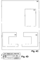
- Figs. 4A-4N collectively illustrate the results obtained through the operation of the scanned region type sensitivity logic 110 of Figs. 1, 2 and 3.
- Fig. 4A is a view illustrating a representative scanned page 150.
- Page 150 illustratively includes text over white background 151, photograph 152, drawing 154, text over shaded background 156, larger font size text 157, special text 158, and inverted text 159.
- Page 150 can be, for example, a typical page in a magazine, book, or document in which multiple types of information are contained on a page.
- Fig. 4B illustrates slide bar 36 having a setting illustrated by pointer 51 in which the text sensitivity is minimized.
- slide bar 36 instructs scanned region type sensitivity logic 110 to display no text at all and page 150 would appear as blank.
- Figs. 4C and 4D illustrate scanned page 150 in which a minimal amount of text over white background 151 is displayed, corresponding to a minimal setting of pointer 51 of slide bar 36 (Fig. 4D). Notice that pointer 51 is adjusted slightly away from the setting illustrated in Fig. 4B, in which no text was displayed. Essentially, by increasing the sensitivity of an attribute (in this example, text) via slide bar 36, the scanned region type sensitivity logic 110 makes more regions appear as text. This corresponds to the description of the probability algorithm described with respect to Fig. 2. For example, text probability is assigned as 0.45. By moving pointer 51 of slide bar 36 to the right (thus increasing text sensitivity) additional "p-value" is added to the text probability. In this manner more of the image will appear as text.
- p-value is added to the text probability.
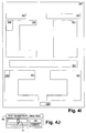
- Figs. 4E and 4F illustrate scanned page 150 in which the pointer 51 of slide bar 36 (Fig. 4F) is adjusted to increase further the text sensitivity.
- both text over white background 151 and text over shaded background 156 is now displayed.
- additional text is displayed.
- movement of slide bar 36 tips the p-value "balance" in favor of regions being classified as text even if they originally had a higher probability of being classified as another type of region.
- This feature gives the user of a scanner product heretofore unavailable ability to manipulate the region sensitivity and allows a user to efficiently tailor the appearance of a scanned image for any particular application.
- Figs. 4G and 4H illustrate scanned page 150 in which pointer 51 of slide bar 36 (Fig. 4H) is adjusted to increase further the sensitivity of scanned text.
- pointer 51 of slide bar 36 Fig. 4H
- this higher sensitivity adjustment is larger font size text 157.
- by increasing the sensitivity of the scanned region type sensitivity logic 110 using slide bar 36 more and more regions that were initially classified as something other than text are caused to appear as text.
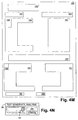
- Figs. 4I and 4J illustrate scanned page 150 in which pointer 51 of slide bar 36 (Fig. 4J) is adjusted yet higher in sensitivity.
- special text 158 now appears in the scanned image.
- Special text 158 may be, for example, a larger font size first letter of a paragraph that may have initially been classified by analysis code 17 as a drawing due to its larger size, but, due to the increase in text sensitivity as requested by a user through input from slide bar 36, is now shown as text.
- Special text 158 may also be, for example, part of a logo at the bottom of page 150.
- Figs. 4K and 4L illustrate scanned page 150 in which pointer 51 of slide bar 36 (Fig. 4L) is adjusted even higher in sensitivity.
- This adjustment now causes scanned region type sensitivity logic 110 to display inverted text 159 as text.
- Inverted text 159 can be text in which the foreground and background colors have been reversed, for example, from black text with white background to white text with black background.
- Inverted text 159 may have initially been classified by analysis code 17 as drawing information, but is now displayed as text.
- Figs. 4M and 4N illustrate scanned page 150 in which pointer 51 of slide bar 36 (Fig. 4N) is adjusted to a maximum sensitivity causing extraneous writing 161 (which is illustratively stray handwriting on the page) to be displayed to a user as text.
- extraneous writing 161 which is illustratively stray handwriting on the page
- region attributes may include all available region types including, but not limited to, drawings, photographs, equations, tables, etc.
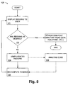
- Fig. 5 is a flow diagram illustrating the operation of the scanned region clustering/declustering logic 120 of Figs. 1 and 2.
- the scanned regions are displayed to a user on display 19.
- the regions are displayed in accordance with the default settings applied by analysis code 17.
- analysis code 17 contains all the data pertaining to each region, only the region clustering generated by the default settings are displayed initially.
- block 122 it is determined whether the user is satisfied with the regions as displayed in block 121. If the user is satisfied with the displayed regions, then in block 127 post analysis tasks such as faxing, printing, optical character recognition, etc. , are performed as those skilled in the art will appreciate. If however, in decision block 122 it is determined that the regions as displayed are not as desired by a user, then through the use of the scanned region clustering/dedustering logic 120 and right click element 37, a user may adjust the clustering of any displayed region so that the desired attributes for the user's particular application are displayed.
- the user updates the desired regions by actuating, for example, right click element 37 in accordance with that described with reference to Fig. 2.
- a user may right click on a particular region and be presented with a list of menu choices corresponding to available region grouping adjustment options
- the user may adjust the clustering, or grouping, of the regions in order to obtain the desired region clustering.
- analysis code 17 is accessed in order to obtain the desired region characteristics, and in block 126, the regions are recomputed and once again displayed to a user on display 19 with the region clustering updated in real time.
- the user may accept the revised region clustering or may adjust the region clustering again.
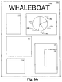
- Figs. 6A-6E collectively illustrate the results obtained by the operation of the scanned region clustering/declustering logic 120 of Figs. 1, 2 and 5.
- Fig. 6A is a view illustrating a scanned image 170.
- Scanned image 170 illustratively includes text 171, photographs 172, large text 174, business graphic 177 in the form of a pie chart, and text 178 surrounding business graphic 177.
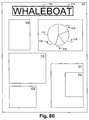
- Fig. 6B is a view illustrating pie chart 177 selected by a user of a scanner by right clicking 37 (Fig. 2) through user interface 13 (Fig. 2). By right clicking, a menu 175 may be presented to a user on display 19 giving the user a selection of commands with which to manipulate the selected region or regions.
- Fig. 6C is a view illustrating pie chart 177 clustered with text 178 surrounding pie chart 177. This is accomplished by a user of a scanner product right clicking 37 (Fig. 2) a mouse while the cursor is positioned over the pie chart 177. Illustratively, a user right clicks over pie chart 177, and selects menu option "form composite". By selecting "form composite” the result is as shown in Fig. 6C wherein pie chart 177 and text 178 surrounding pie chart 177 are clustered together forming region 179. Essentially, the scanned region clustering/declustering logic 120 uses input from a user interface (37 of Fig.
- pie chart region 177 and text 178 surrounding pie chart 177 may by regrouped into region 179 as a "business graphic", or as a new region type.
- region 179 will be segmented, or declustered, resulting in separate regions 177 and 178, as previously illustrated in Fig. 6B.
- Fig. 6D is a view illustrating large text character 176 as selected by a user right clicking over the character.
- a user can cluster the large text into region 181 as shown in Fig. 6E.
- region 181 can be declustered into regions 174 and 176.
- system and method for manipulating regions in a scanned image can be implemented using various scanning and computing products.
- system and method for manipulating regions in a scanned image is useful for manipulating documents from a digital database/file system or from other digital capture devices, such as video capture systems and digital cameras. All such modifications and variations are intended to be included herein within the scope of the present invention, as defined in the claims that follow.
Landscapes
- Engineering & Computer Science (AREA)
- Computer Vision & Pattern Recognition (AREA)
- Artificial Intelligence (AREA)
- Physics & Mathematics (AREA)
- General Physics & Mathematics (AREA)
- Multimedia (AREA)
- Theoretical Computer Science (AREA)
- Facsimiles In General (AREA)
- Facsimile Scanning Arrangements (AREA)
- Facsimile Image Signal Circuits (AREA)
Applications Claiming Priority (2)
| Application Number | Priority Date | Filing Date | Title |
|---|---|---|---|
| US09/159,147 US6263122B1 (en) | 1998-09-23 | 1998-09-23 | System and method for manipulating regions in a scanned image |
| US159147 | 1998-09-23 |
Publications (3)
| Publication Number | Publication Date |
|---|---|
| EP0992934A2 true EP0992934A2 (fr) | 2000-04-12 |
| EP0992934A3 EP0992934A3 (fr) | 2002-01-09 |
| EP0992934B1 EP0992934B1 (fr) | 2008-08-27 |
Family
ID=22571278
Family Applications (1)
| Application Number | Title | Priority Date | Filing Date |
|---|---|---|---|
| EP99109939A Expired - Lifetime EP0992934B1 (fr) | 1998-09-23 | 1999-05-20 | Système et méthode pour manipuler des régions dans une image scannée |
Country Status (4)
| Country | Link |
|---|---|
| US (1) | US6263122B1 (fr) |
| EP (1) | EP0992934B1 (fr) |
| JP (1) | JP2000115476A (fr) |
| DE (1) | DE69939415D1 (fr) |
Cited By (3)
| Publication number | Priority date | Publication date | Assignee | Title |
|---|---|---|---|---|
| SG93868A1 (en) * | 2000-06-07 | 2003-01-21 | Kent Ridge Digital Labs | Method and system for user-configurable clustering of information |
| WO2007024392A1 (fr) * | 2005-08-24 | 2007-03-01 | Hewlett-Packard Development Company, L.P. | Classification de regions definies dans une image numerique |
| US10380554B2 (en) | 2012-06-20 | 2019-08-13 | Hewlett-Packard Development Company, L.P. | Extracting data from email attachments |
Families Citing this family (44)
| Publication number | Priority date | Publication date | Assignee | Title |
|---|---|---|---|---|
| US6151426A (en) * | 1998-10-01 | 2000-11-21 | Hewlett-Packard Company | Click and select user interface for document scanning |
| US6950553B1 (en) * | 2000-03-23 | 2005-09-27 | Cardiff Software, Inc. | Method and system for searching form features for form identification |
| WO2001086585A1 (fr) * | 2000-05-09 | 2001-11-15 | Siemens Aktiengesellschaft | Procede et dispositif de determination d'un objet dans une image |
| US6647144B2 (en) * | 2000-12-04 | 2003-11-11 | Xerox Corporation | Detection and verification of scanning attributes |
| US7254270B2 (en) | 2002-07-09 | 2007-08-07 | Hewlett-Packard Development Company, L.P. | System and method for bounding and classifying regions within a graphical image |
| US7184028B2 (en) * | 2003-01-03 | 2007-02-27 | Kabushiki Kaisha Toshiba | Switchable LCD touchscreen panel scan module |
| US7424672B2 (en) * | 2003-10-03 | 2008-09-09 | Hewlett-Packard Development Company, L.P. | System and method of specifying image document layout definition |
| JP3962721B2 (ja) * | 2003-12-15 | 2007-08-22 | キヤノン株式会社 | 文書処理装置及び文書処理方法 |
| KR100699493B1 (ko) * | 2004-11-11 | 2007-03-26 | 삼성전자주식회사 | 미리보기이미지 구현방법 및 장치 |
| US9769354B2 (en) | 2005-03-24 | 2017-09-19 | Kofax, Inc. | Systems and methods of processing scanned data |
| US9137417B2 (en) | 2005-03-24 | 2015-09-15 | Kofax, Inc. | Systems and methods for processing video data |
| US7479968B2 (en) * | 2006-01-31 | 2009-01-20 | Microsoft Corporation | Semi-transparent highlighting of selected objects in electronic documents |
| US7944592B2 (en) * | 2006-12-18 | 2011-05-17 | Hewlett-Packard Development Company, L.P. | Image capture device |
| US7853074B2 (en) * | 2007-02-26 | 2010-12-14 | Eastman Kodak Company | Multi-color dropout for scanned document |
| JP4470958B2 (ja) * | 2007-05-01 | 2010-06-02 | 村田機械株式会社 | 画像処理装置 |
| US20090323128A1 (en) * | 2008-06-27 | 2009-12-31 | Hari Asuri | System, method, and computer program product for scanning |
| US8443278B2 (en) * | 2009-01-02 | 2013-05-14 | Apple Inc. | Identification of tables in an unstructured document |
| US9767354B2 (en) | 2009-02-10 | 2017-09-19 | Kofax, Inc. | Global geographic information retrieval, validation, and normalization |
| US8774516B2 (en) | 2009-02-10 | 2014-07-08 | Kofax, Inc. | Systems, methods and computer program products for determining document validity |
| US8958605B2 (en) | 2009-02-10 | 2015-02-17 | Kofax, Inc. | Systems, methods and computer program products for determining document validity |
| US9349046B2 (en) | 2009-02-10 | 2016-05-24 | Kofax, Inc. | Smart optical input/output (I/O) extension for context-dependent workflows |
| US9576272B2 (en) | 2009-02-10 | 2017-02-21 | Kofax, Inc. | Systems, methods and computer program products for determining document validity |
| US20100225937A1 (en) * | 2009-03-06 | 2010-09-09 | Simske Steven J | Imaged page warp correction |
| US8913285B1 (en) * | 2009-06-07 | 2014-12-16 | Apple Inc. | Automated method of decomposing scanned documents |
| WO2011001439A2 (fr) | 2009-07-02 | 2011-01-06 | Hewlett-Packard Development Company, L.P. | Détection d'obliquité |
| US20110216342A1 (en) * | 2010-03-08 | 2011-09-08 | Kabushiki Kaisha Toshiba | Image processing device and image processing method |
| US8549399B2 (en) * | 2011-01-18 | 2013-10-01 | Apple Inc. | Identifying a selection of content in a structured document |
| US20130050222A1 (en) * | 2011-08-25 | 2013-02-28 | Dov Moran | Keyboard with embedded display |
| US10146795B2 (en) | 2012-01-12 | 2018-12-04 | Kofax, Inc. | Systems and methods for mobile image capture and processing |
| US9058580B1 (en) | 2012-01-12 | 2015-06-16 | Kofax, Inc. | Systems and methods for identification document processing and business workflow integration |
| US9483794B2 (en) | 2012-01-12 | 2016-11-01 | Kofax, Inc. | Systems and methods for identification document processing and business workflow integration |
| US9058515B1 (en) | 2012-01-12 | 2015-06-16 | Kofax, Inc. | Systems and methods for identification document processing and business workflow integration |
| US9165187B2 (en) | 2012-01-12 | 2015-10-20 | Kofax, Inc. | Systems and methods for mobile image capture and processing |
| US9355312B2 (en) | 2013-03-13 | 2016-05-31 | Kofax, Inc. | Systems and methods for classifying objects in digital images captured using mobile devices |
| US9208536B2 (en) | 2013-09-27 | 2015-12-08 | Kofax, Inc. | Systems and methods for three dimensional geometric reconstruction of captured image data |
| WO2014160426A1 (fr) | 2013-03-13 | 2014-10-02 | Kofax, Inc. | Classification des objets dans des images numériques capturées à l'aide de dispositifs mobiles |
| US20140316841A1 (en) | 2013-04-23 | 2014-10-23 | Kofax, Inc. | Location-based workflows and services |
| WO2014179752A1 (fr) | 2013-05-03 | 2014-11-06 | Kofax, Inc. | Systèmes et procédés pour détecter et classifier des objets dans une vidéo capturée à l'aide de dispositifs mobiles |
| WO2015073920A1 (fr) | 2013-11-15 | 2015-05-21 | Kofax, Inc. | Systèmes et procédés de génération d'images composites de longs documents en utilisant des données vidéo mobiles |
| KR20160027862A (ko) * | 2014-09-02 | 2016-03-10 | 삼성전자주식회사 | 이미지 데이터를 처리하는 방법과 이를 지원하는 전자 장치 |
| US9760788B2 (en) | 2014-10-30 | 2017-09-12 | Kofax, Inc. | Mobile document detection and orientation based on reference object characteristics |
| US10242285B2 (en) | 2015-07-20 | 2019-03-26 | Kofax, Inc. | Iterative recognition-guided thresholding and data extraction |
| US9779296B1 (en) | 2016-04-01 | 2017-10-03 | Kofax, Inc. | Content-based detection and three dimensional geometric reconstruction of objects in image and video data |
| US10803350B2 (en) | 2017-11-30 | 2020-10-13 | Kofax, Inc. | Object detection and image cropping using a multi-detector approach |
Family Cites Families (6)
| Publication number | Priority date | Publication date | Assignee | Title |
|---|---|---|---|---|
| US5048096A (en) * | 1989-12-01 | 1991-09-10 | Eastman Kodak Company | Bi-tonal image non-text matter removal with run length and connected component analysis |
| US5048109A (en) * | 1989-12-08 | 1991-09-10 | Xerox Corporation | Detection of highlighted regions |
| JP2579397B2 (ja) * | 1991-12-18 | 1997-02-05 | インターナショナル・ビジネス・マシーンズ・コーポレイション | 文書画像のレイアウトモデルを作成する方法及び装置 |
| EP0677817B1 (fr) * | 1994-04-15 | 2000-11-08 | Canon Kabushiki Kaisha | Système de segmentation de pages et reconnaissance de caractères |
| US6504540B1 (en) * | 1995-06-19 | 2003-01-07 | Canon Kabushiki Kaisha | Method and apparatus for altering one or more attributes of one or more blocks of image data in a document |
| JPH10188016A (ja) * | 1996-12-27 | 1998-07-21 | Toshiba Corp | ドキュメントリーダ及びドキュメントリーダにおけるレイアウト解析ならびに修正処理方法 |
-
1998
- 1998-09-23 US US09/159,147 patent/US6263122B1/en not_active Expired - Lifetime
-
1999
- 1999-05-20 EP EP99109939A patent/EP0992934B1/fr not_active Expired - Lifetime
- 1999-05-20 DE DE69939415T patent/DE69939415D1/de not_active Expired - Lifetime
- 1999-09-24 JP JP11270886A patent/JP2000115476A/ja active Pending
Cited By (4)
| Publication number | Priority date | Publication date | Assignee | Title |
|---|---|---|---|---|
| SG93868A1 (en) * | 2000-06-07 | 2003-01-21 | Kent Ridge Digital Labs | Method and system for user-configurable clustering of information |
| WO2007024392A1 (fr) * | 2005-08-24 | 2007-03-01 | Hewlett-Packard Development Company, L.P. | Classification de regions definies dans une image numerique |
| US7539343B2 (en) | 2005-08-24 | 2009-05-26 | Hewlett-Packard Development Company, L.P. | Classifying regions defined within a digital image |
| US10380554B2 (en) | 2012-06-20 | 2019-08-13 | Hewlett-Packard Development Company, L.P. | Extracting data from email attachments |
Also Published As
| Publication number | Publication date |
|---|---|
| DE69939415D1 (de) | 2008-10-09 |
| EP0992934A3 (fr) | 2002-01-09 |
| JP2000115476A (ja) | 2000-04-21 |
| US6263122B1 (en) | 2001-07-17 |
| EP0992934B1 (fr) | 2008-08-27 |
Similar Documents
| Publication | Publication Date | Title |
|---|---|---|
| US6263122B1 (en) | System and method for manipulating regions in a scanned image | |
| JP4970714B2 (ja) | 指定されたドキュメント・エリアからのメタデータの抽出 | |
| US10467508B2 (en) | Font recognition using text localization | |
| JP6938422B2 (ja) | 画像処理装置、画像処理方法、およびプログラム | |
| US10699166B2 (en) | Font attributes for font recognition and similarity | |
| US8587614B2 (en) | System and method for image editing of electronic product design | |
| US9152292B2 (en) | Image collage authoring | |
| EP2293187B1 (fr) | Système et procédé de rognage d'image | |
| US20030179214A1 (en) | System and method for editing electronic images | |
| EP1661064B1 (fr) | Lecteur optique pour documents | |
| US7093202B2 (en) | Method and system for interpreting imprecise object selection paths | |
| US7692652B2 (en) | Selectively transforming overlapping illustration artwork | |
| US12029987B2 (en) | Image processing apparatus, image processing method, image processing program, and recording medium storing image processing program | |
| US11495040B2 (en) | Information processing apparatus for designation of image type, image reading apparatus, and non-transitory computer readable medium storing program | |
| JP2007049388A (ja) | 画像処理装置及びその制御方法、プログラム | |
| JP7669143B2 (ja) | 画像処理装置、画像処理方法、及びプログラム | |
| US7042594B1 (en) | System and method for saving handwriting as an annotation in a scanned document | |
| JP7446877B2 (ja) | 画像処理装置、画像処理方法、及びプログラム | |
| JP2024501444A (ja) | メディアコンテンツのオーバーレイに適した画像スペースの検出 | |
| US20260016940A1 (en) | Information processing apparatus, information processing method, and storage medium | |
| JP7558730B2 (ja) | 情報処理装置、情報処理方法及びプログラム | |
| US12315051B2 (en) | Reference based digital content stylization | |
| US20250265857A1 (en) | Image processing system | |
| US20260065553A1 (en) | Information processing apparatus, information processing method, and storage medium | |
| Safonov et al. | Scanned Text Vectorization |
Legal Events
| Date | Code | Title | Description |
|---|---|---|---|
| PUAI | Public reference made under article 153(3) epc to a published international application that has entered the european phase |
Free format text: ORIGINAL CODE: 0009012 |
|
| AK | Designated contracting states |
Kind code of ref document: A2 Designated state(s): AT BE CH CY DE DK ES FI FR GB GR IE IT LI LU MC NL PT SE Kind code of ref document: A2 Designated state(s): DE FR GB |
|
| AX | Request for extension of the european patent |
Free format text: AL;LT;LV;MK;RO;SI |
|
| RAP1 | Party data changed (applicant data changed or rights of an application transferred) |
Owner name: HEWLETT-PACKARD COMPANY, A DELAWARE CORPORATION |
|
| PUAL | Search report despatched |
Free format text: ORIGINAL CODE: 0009013 |
|
| AK | Designated contracting states |
Kind code of ref document: A3 Designated state(s): AT BE CH CY DE DK ES FI FR GB GR IE IT LI LU MC NL PT SE |
|
| AX | Request for extension of the european patent |
Free format text: AL;LT;LV;MK;RO;SI |
|
| 17P | Request for examination filed |
Effective date: 20020502 |
|
| AKX | Designation fees paid |
Free format text: DE FR GB |
|
| GRAP | Despatch of communication of intention to grant a patent |
Free format text: ORIGINAL CODE: EPIDOSNIGR1 |
|
| GRAS | Grant fee paid |
Free format text: ORIGINAL CODE: EPIDOSNIGR3 |
|
| GRAA | (expected) grant |
Free format text: ORIGINAL CODE: 0009210 |
|
| AK | Designated contracting states |
Kind code of ref document: B1 Designated state(s): DE FR GB |
|
| REG | Reference to a national code |
Ref country code: GB Ref legal event code: FG4D |
|
| REF | Corresponds to: |
Ref document number: 69939415 Country of ref document: DE Date of ref document: 20081009 Kind code of ref document: P |
|
| PLBE | No opposition filed within time limit |
Free format text: ORIGINAL CODE: 0009261 |
|
| STAA | Information on the status of an ep patent application or granted ep patent |
Free format text: STATUS: NO OPPOSITION FILED WITHIN TIME LIMIT |
|
| 26N | No opposition filed |
Effective date: 20090528 |
|
| REG | Reference to a national code |
Ref country code: GB Ref legal event code: 732E Free format text: REGISTERED BETWEEN 20120329 AND 20120404 |
|
| REG | Reference to a national code |
Ref country code: FR Ref legal event code: PLFP Year of fee payment: 18 |
|
| PGFP | Annual fee paid to national office [announced via postgrant information from national office to epo] |
Ref country code: GB Payment date: 20160426 Year of fee payment: 18 Ref country code: DE Payment date: 20160421 Year of fee payment: 18 |
|
| PGFP | Annual fee paid to national office [announced via postgrant information from national office to epo] |
Ref country code: FR Payment date: 20160422 Year of fee payment: 18 |
|
| REG | Reference to a national code |
Ref country code: DE Ref legal event code: R119 Ref document number: 69939415 Country of ref document: DE |
|
| GBPC | Gb: european patent ceased through non-payment of renewal fee |
Effective date: 20170520 |
|
| REG | Reference to a national code |
Ref country code: FR Ref legal event code: ST Effective date: 20180131 |
|
| PG25 | Lapsed in a contracting state [announced via postgrant information from national office to epo] |
Ref country code: DE Free format text: LAPSE BECAUSE OF NON-PAYMENT OF DUE FEES Effective date: 20171201 Ref country code: GB Free format text: LAPSE BECAUSE OF NON-PAYMENT OF DUE FEES Effective date: 20170520 |
|
| PG25 | Lapsed in a contracting state [announced via postgrant information from national office to epo] |
Ref country code: FR Free format text: LAPSE BECAUSE OF NON-PAYMENT OF DUE FEES Effective date: 20170531 |