EP0992964B1 - Signalgeber sowie damit ausgerüstete Verkehrssignalanlage - Google Patents
Signalgeber sowie damit ausgerüstete Verkehrssignalanlage Download PDFInfo
- Publication number
- EP0992964B1 EP0992964B1 EP99119128A EP99119128A EP0992964B1 EP 0992964 B1 EP0992964 B1 EP 0992964B1 EP 99119128 A EP99119128 A EP 99119128A EP 99119128 A EP99119128 A EP 99119128A EP 0992964 B1 EP0992964 B1 EP 0992964B1
- Authority
- EP
- European Patent Office
- Prior art keywords
- signal
- traffic
- traffic signal
- signal system
- control
- Prior art date
- Legal status (The legal status is an assumption and is not a legal conclusion. Google has not performed a legal analysis and makes no representation as to the accuracy of the status listed.)
- Expired - Lifetime
Links
Images

Classifications
-
- G—PHYSICS
- G08—SIGNALLING
- G08G—TRAFFIC CONTROL SYSTEMS
- G08G1/00—Traffic control systems for road vehicles
- G08G1/07—Controlling traffic signals
-
- G—PHYSICS
- G08—SIGNALLING
- G08G—TRAFFIC CONTROL SYSTEMS
- G08G1/00—Traffic control systems for road vehicles
- G08G1/09—Arrangements for giving variable traffic instructions
- G08G1/095—Traffic lights
Definitions
- the invention relates to a traffic signal system according to the preamble of claim 1.
- a stand-alone traffic signal system for example for regulating traffic at a road intersection, which are installed only on their driveways, according to a fixed predetermined signal program operating signal generators equipped is today probably only as conventional to call.
- Road traffic control systems much more complex Fulfill tasks.
- traffic signal systems cross-linked with each other to the To be able to keep traffic flowing in a main traffic artery, So in particular multiple stops and restarting the To avoid motor vehicles as much as possible.
- modern Traffic signal systems often means for vehicle detection at least assigned in the direction of the authoritative traffic flows, to enable on-demand traffic management.
- From US-A-5 777 564 is as an example of a modern traffic signal system known how to use vehicle detectors, in the area of one or more intersections of a Traffic route are arranged, the flow of traffic through the Control individual intersections as needed and thus optimize them can. As this example teaches, the technical Effort to cope with these requirements considerably.
- Vehicle detectors are needed many times as in the Lanes embedded induction loops, but for example also as passive infrared or traffic radar detectors are formed. For traffic determination can also next Video cameras are used.
- the traffic information provided by these sensors need to be processed and processed to make it one derive the current traffic streams tuned signal program, with that finally the different signalers the traffic signal system to be operated.
- a centralized Organized or decentralized computer system naturally also become corresponding transmission paths from the peripheral units to the computer system or from Computer system to the peripheral controllers and units needed.
- the actual supply lines for the individual units of the traffic signal system are therefore also corresponding line connections for information transmission required. It can be seen that especially the Operation of modern traffic signal systems with a considerable technical investment.
- Document EP-A-0, 296, 426 relates to a data transmission system for Road signaling systems, which for the control and Femments of Intersection devices of the traffic signal system from a central traffic computer out serves.
- the present invention is therefore based on the object indicate a traffic signaling system which, with little planning and installation effort in a flexible manner to different Needs to be adjusted.
- a signal generator designed according to the invention technological advances that enable smaller designs, exploited with advantage. It is departed from the idea, that a signal generator, suspended from a mast, solely the function serves, optical signals to send out and from him not too far away a device control is set up about him for his operation the required electrical energy and control information be supplied. Conventional signal generator of this type possibly have a signal control, by the alternative the individual light signals, triggered by the Device control, be activated.
- both smaller and more complex traffic signal systems create, their structure, especially in terms of control of the signalers, instead of one in the essentially centrally organized one more decentralized organized Owns structure.
- This is achieved in that more "intelligence" in the periphery of the traffic signal system, So moved into the signal generator itself. That's how it turns out the conventional auto switch that acts as a passive device too is an active device in which is already essential Parts of the control functions executed independently become.
- Traffic signal systems can, on building on this structure, from a plurality of groups respectively interconnected signaling device consist, with a central traffic computer takes over the system control and communicates with the control computers via data transmission lines, those in the respective group of signalers the Assigned to a main control function.
- Every signaler is one with it equipped traffic signal system - in dual function - both a controlled light sensor as well as a device for Detecting momentary vehicle movements in its detection area. Determined via his vehicle detector (s) Vehicle information can be in your own tax calculator, on a case-by-case basis in the control computer, for a group of signalers performs the function of the main controller, processed become. In a self-sufficient traffic signal system, it is thus possible, from this a signal program adapted to the current requirement derive only for this traffic signal system.
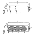
- Figures 1 and 2 is in a front and a rear view the outer shape of a signal generator for road traffic shown. This seems conventional at first glance Signal transmitter has three light signal transmitter 1 for red, Yellow or green light on the front of his housing 2 are assigned. Also, he is like usual siren on one not shown signal mast by means of clamps 3 to fix. But exhausted in its appearance the match with signalers that everyone out knows the traffic.
- a first detector arranged. This is formed in this example as a passive infrared detector 4 and in this orientation intended for vehicle movements to capture the - seen in the direction of traffic - lie in front of the signal generator.
- In the area of the bottom of the housing 1 further detectors are provided in this Example as video cameras 5 are formed.
- an antenna 6 is arranged, which serves as a transmitting / receiving antenna is trained.
- FIG. 3 illustrates that this processor unit 8 with input / output devices 81 is equipped and about this with their environment communicated.
- the processor unit 8 call or receive control signals from the signal controller 7, with which it is possible to have a faultless functional state to monitor the light sensor 1.
- the embodiment of Figure 3 is also based, that the processor unit 8 also that of the detectors 4 and 5 detected information about the current traffic condition is supplied.
- the infrared detector 4 or the video cameras 5 each assigned a detector unit 9 and 10 respectively. These prepare the signals from the connected Infrared detector 4 and the video cameras 5 on. details
- the expert is familiar because a traffic monitoring by means of infrared detectors or video cameras themselves as may be assumed to be known.
- z. B. also for the evaluation of recordings of the video cameras one Variety of design options, their use of the Structure of the respective traffic control or traffic control system in which a single Signalers only one of possibly many peripheral Represents modules.
- the processor unit 8 not only with the in the signal generator itself integrated units in combination but is also equipped to continue with her spatially separate facilities one Traffic signal system or a traffic guidance system information exchange.
- a communication device 11 connected as a bidirectional remote data transmission device is to be considered and in this example as a radio transmitter / receiver via the connected antenna 6 with the environment communicates.
- this communication device 11 as Interface to surrounding facilities in conjunction with a corresponding transmitting / receiving device as a data transmission device designed for an infrared connection be.
- a wired data transmission via connected data lines, possibly also over it shared supply lines would be conceivable, as in FIG. 3 alternatively by a dashed line Connection of the communication device 11 to a cable 12 is indicated.
- a traffic signal system for example, traffic guidance at only one intersection or junction, without being externally connected, on its own and only equipped with a limited number of signalers.
- a device control housed in a control box, in the area the traffic signal system set up and to the individual signal generator connected via underground cables. about this cable connection provides the device control by predetermined signal program specified individual control signals to the connected signal generator or their Signal controls.
- the processor unit of one of Signal transmitter of the traffic signal system takes over as the main controller the function of the conventionally separately set up Device control, the processor units of the other signal generator
- the traffic signal system will be controlled by this main controller in the manner of a "master-slave" configuration.
- the required communication between the processor units the signal generator is preferably wireless via a radio or Infratrotitati, it is in itself but also possible already existing line connections to use for this data exchange.
- traffic signal systems of the described above as local subsystems as the main control of the respective subsystem functioning processor unit in addition to the functions described also exchanges data with a central traffic computer.
- the central traffic computer are those of the individual Subsystem supplied recorded occupancy data and evaluated. Dependent on this is the main control of each one Subsystem so activated that after this one adapted signal program in turn controls the subsystem.
Landscapes
- Physics & Mathematics (AREA)
- General Physics & Mathematics (AREA)
- Traffic Control Systems (AREA)
Description
Claims (11)
- Verkehrssignalanlage, die eine Mehrzahl von Lichtzeichengeber (1) enthaltenden Signalgebern mit Gehäuse (2) und eine Steuereinheit (7, 8) zur Ansteuerung der Signalgeber nach einem vorgegebenen Signalprogramm umfasst, dadurch gekennzeichnet, daß in das Gehäuse (2) jedes Signalgebers eine Steuereinheit (7, 8) sowie eine Datenübertragungseinrichtung (11) zur Kommunikation mit weiteren Signalgebern der Verkehrssignalanlage integriert sind.
- Verkehrssignalanlage nach Anspruch 1, dadurch gekennzeichnet, daß die Steuereinheit einen das Signalprogramm ausführenden Steuerrechner (8) und eine diesem nachgeordnete Signalansteuerung (7) für die Lichtzeichengeber (1) umfaßt.
- Verkehrssignalanlage nach Anspruch 2, dadurch gekennzeichnet, daß der Steuerrechner (8) einer ihrer Signalgeber als periphere Steuerung für weitere Signalgeber der Verkehrssignalanlage ausgebildet ist, die mit ihm über die jeweiligen Datenübertragungseinrichtungen (11) der einzelnen Signalgeber vernetzbar sind.
- Verkehrssignalanlage nach Anspruch 3, dadurch gekennzeichnet, daß eine externe Schnittstelle der Datenübertragungseinrichtung (11) als leitungsgebundene Schnittstelle zum Anschluß an individuelle Datenleitungen (12) oder an zur Datenübertragung mitbenutzte Versorgungsleitungen ausgebildet ist.
- Verkehrssignalanlage nach Anspruch 3, dadurch gekennzeichnet, daß die Datenübertragungseinrichtung (11) als Modem mit einer daran angeschlossenen Sende-/Empfangseinrichtung (6) ausgebildet ist.
- Verkehrssignalanlage nach Anspruch 5, dadurch gekennzeichnet, daß die Sende-/Empfangseinrichtung (6) als Funkantenne ausgebildet ist.
- Verkehrssignalanlage nach Anspruch 5, dadurch gekennzeichnet, daß die Sende-/Empfangseinrichtung (6) als Infrarotsender/-empfänger ausgebildet ist.
- Verkehrssignalanlage nach einem der Ansprüche 1 bis 7, dadurch gekennzeichnet, daß in das Gehäuse (2) jedes Signalgebers mindestens ein Fahrzeugdetektor (4 bzw. 5) zum Feststellen von sich im Erfassungsbereich des jeweiligen Signalgebers aufhaltenden Fahrzeugen integriert ist.
- Verkehrssignalanlage nach Anspruch 8, dadurch gekennzeichnet, daß der mindestens eine Fahrzeugdetektor (4 bzw. 5) als passiver Infrarotdetektor, als Radardetektor und/oder als Videokamera ausgebildet ist.
- Verkehrssignalanlage nach Anspruch 8 oder 9, dadurch gekennzeichnet, daß dem Fahrzeugdetektor (4 bzw. 5) eine Auswerteeinheit (9 bzw. 10) zugeordnet ist, die mit dem Steuerrechner (8) bzw. der Datenübertragungseinrichtung (11, 6) zum Datenaustausch in Kommunikationsverbindung steht.
- Verkehrssignalanlage nach Anspruch 10, dadurch gekennzeichnet, daß diese in Form eines sich auf lokaler Ebene selbst steuernden Subsystemes eine von mehreren gleichartigen Untereinheiten eines umfassenderen Verkehrslenkungssystemes bildet, bei dem ein zentraler Verkehrsrechner vorgesehen ist, der als Führungsrechner für die dann nachgeordneten Hauptsteuerungen (8) der Untereinheiten bzw. Subsysteme ausgebildet ist und mit diesen Verkehrs- und/oder Steuerdaten über deren Einrichtungen (z. B. 6, 11) zum Datenaustausch austauscht.
Applications Claiming Priority (2)
| Application Number | Priority Date | Filing Date | Title |
|---|---|---|---|
| DE19846229 | 1998-10-07 | ||
| DE19846229 | 1998-10-07 |
Publications (3)
| Publication Number | Publication Date |
|---|---|
| EP0992964A2 EP0992964A2 (de) | 2000-04-12 |
| EP0992964A3 EP0992964A3 (de) | 2000-10-04 |
| EP0992964B1 true EP0992964B1 (de) | 2005-12-21 |
Family
ID=7883723
Family Applications (1)
| Application Number | Title | Priority Date | Filing Date |
|---|---|---|---|
| EP99119128A Expired - Lifetime EP0992964B1 (de) | 1998-10-07 | 1999-10-05 | Signalgeber sowie damit ausgerüstete Verkehrssignalanlage |
Country Status (3)
| Country | Link |
|---|---|
| EP (1) | EP0992964B1 (de) |
| AT (1) | ATE313838T1 (de) |
| DE (1) | DE59912955D1 (de) |
Families Citing this family (6)
| Publication number | Priority date | Publication date | Assignee | Title |
|---|---|---|---|---|
| AU2003901485A0 (en) * | 2003-04-01 | 2003-04-17 | Wireless Traffic Technologies Pty Limited | Traffic control system |
| DE102005032719A1 (de) * | 2005-07-13 | 2007-01-25 | Siemens Ag | Lichtsignalanlage, insbesondere für den Straßenverkehr |
| DE102007047847B4 (de) * | 2007-11-22 | 2018-02-22 | Swarco Traffic Systems Gmbh | Verkehrssignalanlage mit Signalgebern und einer Steuereinrichtung zum Steuern von Leuchten in den Signalgebern |
| DE102008003439B4 (de) * | 2008-01-07 | 2009-09-17 | Siemens Aktiengesellschaft | Verkehrssignalisierungsmodul, Verkehrssignalisierungssystem und Verfahren zum Betrieb eines Verkehrssignalisierungssystems |
| DE102009015120B4 (de) | 2009-03-31 | 2011-06-16 | Siemens Aktiengesellschaft | Vorrichtung zur Abgabe von Lichtsignalen und zur Aufnahme von Videobildern im Straßenverkehr |
| GB2621617B (en) * | 2022-08-18 | 2025-04-02 | Srl Traffic Systems Ltd | Improvements in and relating to haul route junctions |
Family Cites Families (4)
| Publication number | Priority date | Publication date | Assignee | Title |
|---|---|---|---|---|
| US4857921A (en) * | 1986-05-30 | 1989-08-15 | Flagman, Inc. | Digital traffic control system |
| EP0296426B1 (de) * | 1987-06-26 | 1994-04-20 | Siemens Aktiengesellschaft | Datenübertragungssystem für Strassenverkehrssignalanlagen |
| US4908615A (en) * | 1987-06-26 | 1990-03-13 | Texas Instruments Incorporated | Traffic light control system and method |
| GB2295475A (en) * | 1994-11-25 | 1996-05-29 | Barry Soden | Signal control system |
-
1999
- 1999-10-05 EP EP99119128A patent/EP0992964B1/de not_active Expired - Lifetime
- 1999-10-05 DE DE59912955T patent/DE59912955D1/de not_active Expired - Lifetime
- 1999-10-05 AT AT99119128T patent/ATE313838T1/de not_active IP Right Cessation
Also Published As
| Publication number | Publication date |
|---|---|
| DE59912955D1 (de) | 2006-01-26 |
| ATE313838T1 (de) | 2006-01-15 |
| EP0992964A2 (de) | 2000-04-12 |
| EP0992964A3 (de) | 2000-10-04 |
Similar Documents
| Publication | Publication Date | Title |
|---|---|---|
| DE4111736C1 (de) | ||
| EP3231690A1 (de) | Verfahren und vorrichtung zur unterstützung eines parkmanövers | |
| DE3417956C2 (de) | ||
| EP1088294B1 (de) | Automatisierungssystem mit funksensor | |
| DE202009018539U1 (de) | Warnleuchtvorrichtung mit wenigstens zwei Warnleuchten | |
| EP0992964B1 (de) | Signalgeber sowie damit ausgerüstete Verkehrssignalanlage | |
| EP0811528B1 (de) | Ansteuereinrichtung | |
| EP1288883B1 (de) | Verfahren und Anordnung zur Steuerung eines Systems von mehreren Verkehrssignalen | |
| CH664462A5 (de) | Koppeleinrichtung fuer einen lichtwellenleiter. | |
| DE10142250A1 (de) | Verfahren und Anordnung zur Steuerung eines Systems von mehreren Verkehrssignalen | |
| EP1606785B1 (de) | Flughafenbefeuerungseinheit und -system | |
| DE102012220956A1 (de) | Erfassungssystem für ein automatisiertes Fahrzeug | |
| EP0424664A2 (de) | Einrichtung zur Übertragung von Steuerungsinformation auf ein Schienenfahrzeug | |
| EP1246150A2 (de) | Brandmeldeanlage | |
| DE19906095A1 (de) | Schaltungsanordnung zur elektrischen Vernetzung von Sensoren und/oder Aktoren in einem Kraftfahrzeug | |
| DE10158678B4 (de) | Mobile Lichtsignalanlage und Verfahren zu ihrer Steuerung | |
| DE4307486A1 (de) | Verkehrsregelungseinrichtung | |
| DE102017002061A1 (de) | Steuergerät für ein Fahrzeug sowie Fahrzeug mit einem derartigen Steuergerät | |
| DE4334980C2 (de) | Ein-Ausgabeelement für Hydraulikanwendungen | |
| DE3209753C2 (de) | Steuereinrichtung zum Betrieb eines Informationsgerätes | |
| EP0995180B1 (de) | Verfahren und vorrichtung zur verkehrsabhängigen steuerung von lichtsignalanlagen | |
| DE4428822C1 (de) | Verfahren und Einrichtung zur Warnung von Personen im Gleisbereich | |
| DE19648130A1 (de) | Verkehrs-Informationssystem | |
| EP0962006B1 (de) | Datenübertragungseinrichtung für verkehrsleit- und verkehrsinformationssysteme | |
| DE102024210643A1 (de) | Verfahren zum Betrieb eines Verkehrssystem und Verkehrssystem |
Legal Events
| Date | Code | Title | Description |
|---|---|---|---|
| PUAI | Public reference made under article 153(3) epc to a published international application that has entered the european phase |
Free format text: ORIGINAL CODE: 0009012 |
|
| AK | Designated contracting states |
Kind code of ref document: A2 Designated state(s): AT BE CH CY DE DK ES FI FR GB GR IE IT LI LU MC NL PT SE |
|
| AX | Request for extension of the european patent |
Free format text: AL;LT;LV;MK;RO;SI |
|
| PUAL | Search report despatched |
Free format text: ORIGINAL CODE: 0009013 |
|
| AK | Designated contracting states |
Kind code of ref document: A3 Designated state(s): AT BE CH CY DE DK ES FI FR GB GR IE IT LI LU MC NL PT SE |
|
| AX | Request for extension of the european patent |
Free format text: AL;LT;LV;MK;RO;SI |
|
| 17P | Request for examination filed |
Effective date: 20010305 |
|
| AKX | Designation fees paid |
Free format text: AT BE CH CY DE DK ES FI FR GB GR IE IT LI LU MC NL PT SE |
|
| 17Q | First examination report despatched |
Effective date: 20030509 |
|
| GRAP | Despatch of communication of intention to grant a patent |
Free format text: ORIGINAL CODE: EPIDOSNIGR1 |
|
| GRAS | Grant fee paid |
Free format text: ORIGINAL CODE: EPIDOSNIGR3 |
|
| GRAA | (expected) grant |
Free format text: ORIGINAL CODE: 0009210 |
|
| AK | Designated contracting states |
Kind code of ref document: B1 Designated state(s): AT BE CH CY DE DK ES FI FR GB GR IE IT LI LU MC NL PT SE |
|
| PG25 | Lapsed in a contracting state [announced via postgrant information from national office to epo] |
Ref country code: IT Free format text: LAPSE BECAUSE OF FAILURE TO SUBMIT A TRANSLATION OF THE DESCRIPTION OR TO PAY THE FEE WITHIN THE PRESCRIBED TIME-LIMIT;WARNING: LAPSES OF ITALIAN PATENTS WITH EFFECTIVE DATE BEFORE 2007 MAY HAVE OCCURRED AT ANY TIME BEFORE 2007. THE CORRECT EFFECTIVE DATE MAY BE DIFFERENT FROM THE ONE RECORDED. Effective date: 20051221 Ref country code: IE Free format text: LAPSE BECAUSE OF FAILURE TO SUBMIT A TRANSLATION OF THE DESCRIPTION OR TO PAY THE FEE WITHIN THE PRESCRIBED TIME-LIMIT Effective date: 20051221 Ref country code: FI Free format text: LAPSE BECAUSE OF FAILURE TO SUBMIT A TRANSLATION OF THE DESCRIPTION OR TO PAY THE FEE WITHIN THE PRESCRIBED TIME-LIMIT Effective date: 20051221 |
|
| REG | Reference to a national code |
Ref country code: GB Ref legal event code: FG4D Free format text: NOT ENGLISH |
|
| REG | Reference to a national code |
Ref country code: CH Ref legal event code: NV Representative=s name: SIEMENS SCHWEIZ AG Ref country code: CH Ref legal event code: EP |
|
| REG | Reference to a national code |
Ref country code: IE Ref legal event code: FG4D Free format text: LANGUAGE OF EP DOCUMENT: GERMAN |
|
| REF | Corresponds to: |
Ref document number: 59912955 Country of ref document: DE Date of ref document: 20060126 Kind code of ref document: P |
|
| GBT | Gb: translation of ep patent filed (gb section 77(6)(a)/1977) |
Effective date: 20060213 |
|
| PG25 | Lapsed in a contracting state [announced via postgrant information from national office to epo] |
Ref country code: SE Free format text: LAPSE BECAUSE OF FAILURE TO SUBMIT A TRANSLATION OF THE DESCRIPTION OR TO PAY THE FEE WITHIN THE PRESCRIBED TIME-LIMIT Effective date: 20060321 Ref country code: GR Free format text: LAPSE BECAUSE OF FAILURE TO SUBMIT A TRANSLATION OF THE DESCRIPTION OR TO PAY THE FEE WITHIN THE PRESCRIBED TIME-LIMIT Effective date: 20060321 Ref country code: DK Free format text: LAPSE BECAUSE OF FAILURE TO SUBMIT A TRANSLATION OF THE DESCRIPTION OR TO PAY THE FEE WITHIN THE PRESCRIBED TIME-LIMIT Effective date: 20060321 |
|
| PG25 | Lapsed in a contracting state [announced via postgrant information from national office to epo] |
Ref country code: ES Free format text: LAPSE BECAUSE OF FAILURE TO SUBMIT A TRANSLATION OF THE DESCRIPTION OR TO PAY THE FEE WITHIN THE PRESCRIBED TIME-LIMIT Effective date: 20060401 |
|
| PG25 | Lapsed in a contracting state [announced via postgrant information from national office to epo] |
Ref country code: PT Free format text: LAPSE BECAUSE OF FAILURE TO SUBMIT A TRANSLATION OF THE DESCRIPTION OR TO PAY THE FEE WITHIN THE PRESCRIBED TIME-LIMIT Effective date: 20060522 |
|
| REG | Reference to a national code |
Ref country code: IE Ref legal event code: FD4D |
|
| PGFP | Annual fee paid to national office [announced via postgrant information from national office to epo] |
Ref country code: NL Payment date: 20061006 Year of fee payment: 8 |
|
| PGFP | Annual fee paid to national office [announced via postgrant information from national office to epo] |
Ref country code: GB Payment date: 20061012 Year of fee payment: 8 |
|
| PG25 | Lapsed in a contracting state [announced via postgrant information from national office to epo] |
Ref country code: MC Free format text: LAPSE BECAUSE OF NON-PAYMENT OF DUE FEES Effective date: 20061031 |
|
| PLBE | No opposition filed within time limit |
Free format text: ORIGINAL CODE: 0009261 |
|
| STAA | Information on the status of an ep patent application or granted ep patent |
Free format text: STATUS: NO OPPOSITION FILED WITHIN TIME LIMIT |
|
| 26N | No opposition filed |
Effective date: 20060922 |
|
| EN | Fr: translation not filed | ||
| BERE | Be: lapsed |
Owner name: SIEMENS A.G. Effective date: 20061031 |
|
| PG25 | Lapsed in a contracting state [announced via postgrant information from national office to epo] |
Ref country code: FR Free format text: LAPSE BECAUSE OF FAILURE TO SUBMIT A TRANSLATION OF THE DESCRIPTION OR TO PAY THE FEE WITHIN THE PRESCRIBED TIME-LIMIT Effective date: 20070209 |
|
| GBPC | Gb: european patent ceased through non-payment of renewal fee |
Effective date: 20071005 |
|
| NLV4 | Nl: lapsed or anulled due to non-payment of the annual fee |
Effective date: 20080501 |
|
| PG25 | Lapsed in a contracting state [announced via postgrant information from national office to epo] |
Ref country code: LU Free format text: LAPSE BECAUSE OF NON-PAYMENT OF DUE FEES Effective date: 20061005 |
|
| PG25 | Lapsed in a contracting state [announced via postgrant information from national office to epo] |
Ref country code: NL Free format text: LAPSE BECAUSE OF NON-PAYMENT OF DUE FEES Effective date: 20080501 |
|
| PG25 | Lapsed in a contracting state [announced via postgrant information from national office to epo] |
Ref country code: GB Free format text: LAPSE BECAUSE OF NON-PAYMENT OF DUE FEES Effective date: 20071005 Ref country code: FR Free format text: LAPSE BECAUSE OF FAILURE TO SUBMIT A TRANSLATION OF THE DESCRIPTION OR TO PAY THE FEE WITHIN THE PRESCRIBED TIME-LIMIT Effective date: 20051221 Ref country code: CY Free format text: LAPSE BECAUSE OF FAILURE TO SUBMIT A TRANSLATION OF THE DESCRIPTION OR TO PAY THE FEE WITHIN THE PRESCRIBED TIME-LIMIT Effective date: 20051221 |
|
| REG | Reference to a national code |
Ref country code: CH Ref legal event code: PCAR Free format text: SIEMENS SCHWEIZ AG;INTELLECTUAL PROPERTY FREILAGERSTRASSE 40;8047 ZUERICH (CH) |
|
| PG25 | Lapsed in a contracting state [announced via postgrant information from national office to epo] |
Ref country code: BE Free format text: LAPSE BECAUSE OF FAILURE TO SUBMIT A TRANSLATION OF THE DESCRIPTION OR TO PAY THE FEE WITHIN THE PRESCRIBED TIME-LIMIT Effective date: 20061031 |
|
| PGFP | Annual fee paid to national office [announced via postgrant information from national office to epo] |
Ref country code: AT Payment date: 20090910 Year of fee payment: 11 |
|
| PGFP | Annual fee paid to national office [announced via postgrant information from national office to epo] |
Ref country code: CH Payment date: 20100112 Year of fee payment: 11 |
|
| PGFP | Annual fee paid to national office [announced via postgrant information from national office to epo] |
Ref country code: DE Payment date: 20091218 Year of fee payment: 11 |
|
| REG | Reference to a national code |
Ref country code: CH Ref legal event code: PL |
|
| PG25 | Lapsed in a contracting state [announced via postgrant information from national office to epo] |
Ref country code: CH Free format text: LAPSE BECAUSE OF NON-PAYMENT OF DUE FEES Effective date: 20101031 Ref country code: LI Free format text: LAPSE BECAUSE OF NON-PAYMENT OF DUE FEES Effective date: 20101031 |
|
| PG25 | Lapsed in a contracting state [announced via postgrant information from national office to epo] |
Ref country code: AT Free format text: LAPSE BECAUSE OF NON-PAYMENT OF DUE FEES Effective date: 20101005 |
|
| REG | Reference to a national code |
Ref country code: DE Ref legal event code: R119 Ref document number: 59912955 Country of ref document: DE Effective date: 20110502 |
|
| PG25 | Lapsed in a contracting state [announced via postgrant information from national office to epo] |
Ref country code: DE Free format text: LAPSE BECAUSE OF NON-PAYMENT OF DUE FEES Effective date: 20110502 |