EP0993010B1 - Stufenschalter für elektrische Transformatoren - Google Patents
Stufenschalter für elektrische Transformatoren Download PDFInfo
- Publication number
- EP0993010B1 EP0993010B1 EP99116761A EP99116761A EP0993010B1 EP 0993010 B1 EP0993010 B1 EP 0993010B1 EP 99116761 A EP99116761 A EP 99116761A EP 99116761 A EP99116761 A EP 99116761A EP 0993010 B1 EP0993010 B1 EP 0993010B1
- Authority
- EP
- European Patent Office
- Prior art keywords
- shaped
- movable contacts
- contacts
- tap changer
- rod
- Prior art date
- Legal status (The legal status is an assumption and is not a legal conclusion. Google has not performed a legal analysis and makes no representation as to the accuracy of the status listed.)
- Expired - Lifetime
Links
- 238000004873 anchoring Methods 0.000 claims abstract description 5
- 230000008878 coupling Effects 0.000 claims description 3
- 238000010168 coupling process Methods 0.000 claims description 3
- 238000005859 coupling reaction Methods 0.000 claims description 3
- 238000003780 insertion Methods 0.000 claims description 2
- 230000037431 insertion Effects 0.000 claims description 2
- 230000014759 maintenance of location Effects 0.000 claims description 2
- 239000002131 composite material Substances 0.000 description 5
- 238000004519 manufacturing process Methods 0.000 description 3
- 239000002184 metal Substances 0.000 description 2
- 230000006978 adaptation Effects 0.000 description 1
- 239000004020 conductor Substances 0.000 description 1
- 230000005489 elastic deformation Effects 0.000 description 1
- 238000005516 engineering process Methods 0.000 description 1
- 230000000670 limiting effect Effects 0.000 description 1
- 238000012986 modification Methods 0.000 description 1
- 230000004048 modification Effects 0.000 description 1
- 238000007789 sealing Methods 0.000 description 1
- 238000007493 shaping process Methods 0.000 description 1
Images

Classifications
-
- H—ELECTRICITY
- H01—ELECTRIC ELEMENTS
- H01H—ELECTRIC SWITCHES; RELAYS; SELECTORS; EMERGENCY PROTECTIVE DEVICES
- H01H9/00—Details of switching devices, not covered by groups H01H1/00 - H01H7/00
- H01H9/0005—Tap change devices
- H01H9/0016—Contact arrangements for tap changers
-
- H—ELECTRICITY
- H01—ELECTRIC ELEMENTS
- H01H—ELECTRIC SWITCHES; RELAYS; SELECTORS; EMERGENCY PROTECTIVE DEVICES
- H01H3/00—Mechanisms for operating contacts
- H01H3/32—Driving mechanisms, i.e. for transmitting driving force to the contacts
- H01H3/40—Driving mechanisms, i.e. for transmitting driving force to the contacts using friction, toothed, or screw-and-nut gearing
-
- H—ELECTRICITY
- H01—ELECTRIC ELEMENTS
- H01H—ELECTRIC SWITCHES; RELAYS; SELECTORS; EMERGENCY PROTECTIVE DEVICES
- H01H9/00—Details of switching devices, not covered by groups H01H1/00 - H01H7/00
- H01H9/0005—Tap change devices
- H01H9/0027—Operating mechanisms
-
- H—ELECTRICITY
- H01—ELECTRIC ELEMENTS
- H01H—ELECTRIC SWITCHES; RELAYS; SELECTORS; EMERGENCY PROTECTIVE DEVICES
- H01H9/00—Details of switching devices, not covered by groups H01H1/00 - H01H7/00
- H01H9/20—Interlocking, locking, or latching mechanisms
- H01H9/28—Interlocking, locking, or latching mechanisms for locking switch parts by a key or equivalent removable member
-
- H—ELECTRICITY
- H01—ELECTRIC ELEMENTS
- H01H—ELECTRIC SWITCHES; RELAYS; SELECTORS; EMERGENCY PROTECTIVE DEVICES
- H01H9/00—Details of switching devices, not covered by groups H01H1/00 - H01H7/00
- H01H9/20—Interlocking, locking, or latching mechanisms
- H01H9/28—Interlocking, locking, or latching mechanisms for locking switch parts by a key or equivalent removable member
- H01H9/281—Interlocking, locking, or latching mechanisms for locking switch parts by a key or equivalent removable member making use of a padlock
Definitions
- the present invention relates to a tap changer for electric transformers.
- Conventional electric tap changers for transformers are substantially composed of a rod-like body which rigidly supports fixed pin-like contacts which are arranged at right angles in series along said body.
- the rod-like body is the sliding guide for a sliding block which is associated with actuation means which can be actuated by the user; the sliding block is provided with at least one support for a corresponding pair of skid-like movable contacts which are slideable on the fixed contacts in mutually opposite positions and are adapted 10 interfere with two of the contacts alternately and in succession.
- tap changers are substantially produced by shaping a metal lamina and as a whole are structurally rather complicated and composed of many parts.
- FR-A-2 401 498 discloses the features of a tap changer according to the preamble of claim 1.
- the aim of the present invention is to provide a tap changer for electric transformers which solves the drawbacks noted above in conventional devices, particularly achieving greater constructive simplicity and a reduced number of components.
- an important objec: of the present invention is to provide a tap changer which nonetheless allows maximum functionality and strength with respect to commercially available tap changers.
- Another object of the present invention is to provide a tap changer which, as a whole, is adapted to reduce production costs and times.
- Another object of the present invention is to provide a tap changer which can be manufactured with conventional technologies and systems.
- a tap changer particularly for electric transformers which comprises a rod-like body which rigidly supports fixed pin-like contacts arranged at right angles and in series along said rod-like body, said rod-like body constituting a sliding guide for a sliding block associated with actuation means which can be actuated by the user, said sliding block having at least one support for a corresponding pair of skid-like movable contacts which are slideable on said fixed contacts in mutually opposite positions and are adapted to interfere with two of said fixed contacts alternately and in succession, characterized in that said at least one support is constituted by a base from which two mutually parallel walls for sliding on said rod-like body protrude, said base being shaped so as to form seats for said two movable contacts, each one of said movable contacts being shaped so as to form at least one anchoring tab which is shaped complementarily to a corresponding guide for retaining said base, a spring being provided which is shaped so as to have two pairs of arms which
- a tap changer for electric transformers according to the invention is generally designated by the reference numeral 10.
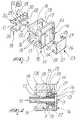
- the tap changer 10 comprises a rod-like body 11 which has a substantially rectangular transverse cross-section and supports fixed pin-like contacts 13 which are rigidly coupled thereto and are arranged at right angles in series along it.
- the rod-like body 11 constitutes a sliding guide for a sliding block 12b which is associated with actuation means, generally designated by the reference numeral 12a and described in greater detail hereinafter, which can be actuated by the user.
- the sliding block 12b carries at least one support and, in this case, three supports 14, one for each corresponding pair of movable skid-like contacts 15 which are slideable on said fixed contacts 13 in mutually opposite positions and are adapted to interfere with two of the fixed contacts alternately and in succession.
- Each one of the supports 14 comprises a base 16 from which two mutually parallel walls 17 for sliding on the rod-like body protrude.
- the walls 17 have, on their mutually opposite inner faces, ribs 18 which as a whole are adapted to form guides 19 for sliding with respect to the body 11.
- the base 16 is also shaped so as to form a slot 24 for inserting (one at a time) two movable contacts 15, each of which comprises, in this case, a strip 21 made of conducting material which is shaped so as to form, again in this case, two tabs 22 which have a substantially dovetail edge which is shaped complementarily to corresponding regions of the base 16 which constitute a corresponding number of retention guides for them.
- the tap changer 10 further comprises, for each one of the supports 14, a corresponding locking spring, generally designated by the reference numeral 23, which is adapted to force toward each other two corresponding movable contacts 15, facilitating interference with the interposed fixed contacts 13.
- the base 16 is substantially frame-like.
- the slot 24 for the insertion of the movable contacts 15 is such that once said movable contacts have been inserted and the spring 23 has been applied, disengagement is not possible.
- a pin 25 for anchoring to the sliding block 12b protrudes from each one of the supports 14.
- the spring 23 is instead formed by blanking and plastic deformation from a metal lamina 26 which has four mutually independent arms 27, each of which has a hook-shaped end 28 for coupling to corresponding seats 29 formed in corresponding movable contacts 15.
- each one of the movable contacts 15 also has, on mutually opposite edges, curved regions 30 which are adapted to facilitate sliding on said fixed contacts 13.
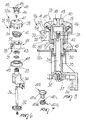
- the actuation means 12a are constituted, in this embodiment, by a longitudinal rack 13 which is integrated with the sliding block 12b and is coupled to a pinion 32 which is fixed to a composite knob 33 which is fixed to the transformer, of which only part of the frame 12c is visible, and which can be actuated manually by the operator.
- the composite knob 33 also comprises, again in this embodiment, a shaped support 34 for the body 11, with an axial hole 35 in which a shaft 36 is rotatably inserted; the end of the shaft 36 that is directed toward the inside of the transformer 37 is fixed to the pinion 32, while the other end 38 is fixed to controlled movement means which can be actuated manually by the operator.
- Such movement means comprise, in a substantially coaxial arrangement, a cap 39 (the knob proper), which is actually available for actuation by the user and is associated with a locking element 40 and, thanks to the interposition of an elastic counterthrust element constituted in this case by a helical spring 41, an adjustable positioning element which is substantially constituted by a flanged cup 42 which has an open bottom and a corresponding shaped rim so as to form a series of substantially semicircular protrusions 43 which are kept inserted, until the operator acts in a different direction of rotation, in corresponding seats 44 formed circumferentially in an annular gasket presser 45.
- the locking element 40 is constituted in this case by an externally threaded tubular portion 46 which has a screw-and-nut coupling with a threaded hole 47 formed coaxially in the locking head 39.
- a head 48 is also associated with the threaded portion 46 and can be actuated by the user by means of adapted cross-shaped ribs 49.
- the composite knob 33 furthermore has, in this case, annular sealing gaskets, all of which are designated by the reference numeral 50.
- a device for locking the composite knob 33 which comprises a tab 51 protruding radially from the cup 42 and has an axial protrusion 52 inserted in an adapted through hole 53 of a tab 54 which protrudes radially from the cap 39.
- the axial protrusion 52 has two through holes 55 at different levels in which it is possible to insert a padlock, not shown, which locks the movement of the cup 42.
- the locking element 40 is replaced with two combined elements: an externally threaded bush 40a, to be coupled to the thread of the hole 47, and a knob 40b, to be coupled to the bush 40a.
- the bush in fact has a cross-shaped axial through hole 40c in which a complementarily shaped tab 40d of the knob 40b fits.
- the knob 40b also has a frustum-shaped external protrusion 40e which couples by snap action and elastic deformation with an undercut seat, not shown in the Figures, of the cap 39, with which it is accordingly stably associated.
- the structure of the tap changer allows easy adaptability to various kinds of transformer even if already in production.
- the composite knob 33 is adapted for a plurality of frame thicknesses because axial adaptation of the gasket presser 45 occurs, raising or lowering the cup 42, the spring 41 and the cap 39.
- the structure of the tap changer is such that when the plug 40, however provided, is fixed, the protrusions 43 are forced toward the correct position.
Landscapes
- Push-Button Switches (AREA)
- Driving Mechanisms And Operating Circuits Of Arc-Extinguishing High-Tension Switches (AREA)
- Keying Circuit Devices (AREA)
- Switch Cases, Indication, And Locking (AREA)
- Connector Housings Or Holding Contact Members (AREA)
- Gas-Insulated Switchgears (AREA)
- Coils Or Transformers For Communication (AREA)
- Circuit Arrangements For Discharge Lamps (AREA)
- Slide Switches (AREA)
Claims (8)
- Stufenschalter (10), insbesondere für elektrische Transformatoren, mit einem stabartigen Körper (11), an dem stiftartige Festkontakte (13) unter rechten Winkeln und in einer Reihe längs dem stabartigen Körper (11) starr angeordnet sind, wobei der stabartige Körper (11) eine Schiebeführung eines Schiebers (12b) bildet, der mit vom Benutzer betätigbaren Betätigungseinrichtungen versehenen ist und mindestens einen Halter (14) für ein entsprechendes Paar von gleitschuhartigen bewegbaren Kontakten (15) aufweist, die so gestaltet sind, dass sie an einander gegenüberliegenden Stellen der Festkontaktes (13) gleiten und abwechselnd und nacheinander an zwei der Festkontakte (13) angreifen, wobei der mindestens eine Halter (14) eine Basis (16) aufweist, von der zwei zueinander parallele, an dem stabartigen Körper (11) gleitende Wände (17) ausgehen, wobei die Basis (16) so gestaltet ist, dass sie für die beiden bewegbaren Kontakte (15) Sitze bildet, und wobei jeder der bewegbaren Kontakte (15) mit mindestens einer Verankerungsnase (22) ausgebildet ist, die komplementär zu einer entsprechenden Führung zur Halterung an der Basis (16) geformt ist, gekennzeichnet durch eine Feder (23) mit zwei Paaren von Armen (27), die die bewegbaren Kontakte (15) aufeinanderzu drücken.
- Stufenschalter (10) nach Anspruch 1, dadurch gekennzeichnet, dass er mindestens zwei Halter (14) aufweist, deren jeder an einer entsprechenden Gruppe der bewegbaren Kontakte (15) angeordnet ist.
- Stufenschalter (10) nach Anspruch 1, dadurch gekennzeichnet, dass die Basis (16) nahe ihren Kanten mindestens eine Vertiefung (24) zum individuellen Einsetzen der entsprechenden bewegbaren Kontakte (15) aufweist.
- Stufenschalter (10) nach Anspruch 2, dadurch gekennzeichnet, dass jeder der Halter (14) einen Stift (25) zur Verankerung an dem Schieber (12b) und zur Führung aufweist.
- Stufenschalter (10) nach Anspruch 1, dadurch gekennzeichnet, dass jeder der bewegbaren Kontakte (15) gekrümmte Seitenbereiche (30) zum leichteren Gleiten an den Festkontakten (13) aufweist.
- Stufenschalter (10) nach Anspruch 1, dadurch gekennzeichnet, dass jeder der bewegbaren Kontakte (15) zwei im wesentlichen jeweils schwalbenschwanzförmige Nasen (22) aufweist.
- Stufenschalter (10) nach Anspruch 6, dadurch gekennzeichnet, dass die Basis (16) mit im wesentlichen komplementär zu den Nasen (22) geformten Kantenteilen ausgebildet ist.
- Stufenschalter (10) nach Anspruch 1, dadurch gekennzeichnet, dass die Feder (23) mit vier hakenförmigen Arme (27) zum Ankoppeln an entsprechende, in den jeweiligen bewegbaren Kontakten (15) ausgebildete Sitze (29) versehen ist.
Applications Claiming Priority (2)
| Application Number | Priority Date | Filing Date | Title |
|---|---|---|---|
| IT1998PD000094U IT245092Y1 (it) | 1998-10-06 | 1998-10-06 | Struttura di commutatore per trasformatori elettrici. |
| ITPD980094U | 1998-10-06 |
Publications (3)
| Publication Number | Publication Date |
|---|---|
| EP0993010A2 EP0993010A2 (de) | 2000-04-12 |
| EP0993010A3 EP0993010A3 (de) | 2001-09-05 |
| EP0993010B1 true EP0993010B1 (de) | 2006-05-10 |
Family
ID=11392174
Family Applications (1)
| Application Number | Title | Priority Date | Filing Date |
|---|---|---|---|
| EP99116761A Expired - Lifetime EP0993010B1 (de) | 1998-10-06 | 1999-08-30 | Stufenschalter für elektrische Transformatoren |
Country Status (8)
| Country | Link |
|---|---|
| EP (1) | EP0993010B1 (de) |
| AT (1) | ATE326058T1 (de) |
| CY (1) | CY1105121T1 (de) |
| DE (1) | DE69931229T2 (de) |
| DK (1) | DK0993010T3 (de) |
| ES (1) | ES2264817T3 (de) |
| IT (1) | IT245092Y1 (de) |
| PT (1) | PT993010E (de) |
Families Citing this family (3)
| Publication number | Priority date | Publication date | Assignee | Title |
|---|---|---|---|---|
| CN102789911B (zh) * | 2012-08-20 | 2015-07-29 | 武汉泰普变压器开关有限公司 | 无励磁条形分接开关 |
| TR201908022T4 (tr) * | 2014-10-10 | 2019-06-21 | Elettromaule Component S R L | Yağlı tip elektrik trafolarına yönelik bir kademe değiştirici. |
| BR102015013951A2 (pt) * | 2015-06-12 | 2016-12-27 | Riotrafo Ltda | comutador longitudinal, para sistema de mudança de posição e travamento no contato elétrico |
Family Cites Families (3)
| Publication number | Priority date | Publication date | Assignee | Title |
|---|---|---|---|---|
| FR1562235A (de) * | 1968-02-22 | 1969-04-04 | ||
| FR2142219A5 (de) * | 1971-06-17 | 1973-01-26 | Gerardin Maurice | |
| DE2738144A1 (de) * | 1977-08-24 | 1979-03-01 | Reinhausen Maschf Scheubeck | Anzapfumsteller zum aendern des uebersetzungsverhaeltnisses eines transformators |
-
1998
- 1998-10-06 IT IT1998PD000094U patent/IT245092Y1/it active
-
1999
- 1999-08-30 DE DE69931229T patent/DE69931229T2/de not_active Expired - Lifetime
- 1999-08-30 AT AT99116761T patent/ATE326058T1/de active
- 1999-08-30 ES ES99116761T patent/ES2264817T3/es not_active Expired - Lifetime
- 1999-08-30 PT PT99116761T patent/PT993010E/pt unknown
- 1999-08-30 DK DK99116761T patent/DK0993010T3/da active
- 1999-08-30 EP EP99116761A patent/EP0993010B1/de not_active Expired - Lifetime
-
2006
- 2006-08-02 CY CY20061101084T patent/CY1105121T1/el unknown
Also Published As
| Publication number | Publication date |
|---|---|
| ATE326058T1 (de) | 2006-06-15 |
| EP0993010A3 (de) | 2001-09-05 |
| ES2264817T3 (es) | 2007-01-16 |
| DK0993010T3 (da) | 2006-09-18 |
| CY1105121T1 (el) | 2009-11-04 |
| IT245092Y1 (it) | 2002-03-19 |
| EP0993010A2 (de) | 2000-04-12 |
| DE69931229D1 (de) | 2006-06-14 |
| ITPD980094U1 (it) | 2000-04-06 |
| PT993010E (pt) | 2006-09-29 |
| DE69931229T2 (de) | 2007-03-01 |
Similar Documents
| Publication | Publication Date | Title |
|---|---|---|
| US5040758A (en) | Level adjustment device, particularly for furniture | |
| US4251007A (en) | Pressure cooker having safety means | |
| KR100347877B1 (ko) | 브레이크와이어조립체단부클립을구비한제어장치 | |
| EP0977224A2 (de) | Verfahren zur Herstellung eines elektrischen Schaltgeräts | |
| GB2363785A (en) | Guiding structure for a moving member such as a lid | |
| EP0993010A2 (de) | Stufenschalter für elektrische Transformatoren | |
| US20120103769A1 (en) | Electrical switch latch assembly | |
| DE19722611C1 (de) | Elektrischer Schalter | |
| US2979581A (en) | Push button stations | |
| EP1272081B1 (de) | Haushaltsgerät | |
| DE10203509B4 (de) | Rastvorrichtung für einen mehrstufigen Drehschalter | |
| EP0199295B1 (de) | Drehpotentiometer mit Schalter | |
| KR101595841B1 (ko) | 캐스터 | |
| US6185828B1 (en) | Position signal transmitter for a servo drive | |
| DE2805181C2 (de) | Einstellvorrichtung mit Raststufen für Auslöser elektrischer Schaltgeräte | |
| US3201533A (en) | Rotary type control switch | |
| DE10203510C1 (de) | Elektrischer Schalter, der in eine Bedien/Anzeigeblende einbaubar ist | |
| DE1565512C3 (de) | ||
| EP4174889B1 (de) | Beleuchtetes elektroinstallationsgerät wie schalter oder taster | |
| US3172985A (en) | Push button assembly | |
| DE19923722C1 (de) | Kontaktanordnung an einem Vorwähler | |
| DE2803768C3 (de) | Elektrischer Nockenschalter mit angekuppeltem Drehschalter | |
| DE4013074A1 (de) | Einstellbares geraet, insbesondere elektrisches schalt-, steuer- oder regelgeraet | |
| CN217386917U (zh) | 一种开关本体带定位的冷压条形分接开关 | |
| US3914571A (en) | Switch operator with split cam |
Legal Events
| Date | Code | Title | Description |
|---|---|---|---|
| PUAI | Public reference made under article 153(3) epc to a published international application that has entered the european phase |
Free format text: ORIGINAL CODE: 0009012 |
|
| AK | Designated contracting states |
Kind code of ref document: A2 Designated state(s): AT BE CH CY DE DK ES FI FR GB GR IE IT LI LU MC NL PT SE |
|
| AX | Request for extension of the european patent |
Free format text: AL;LT;LV;MK;RO;SI |
|
| PUAL | Search report despatched |
Free format text: ORIGINAL CODE: 0009013 |
|
| AK | Designated contracting states |
Kind code of ref document: A3 Designated state(s): AT BE CH CY DE DK ES FI FR GB GR IE IT LI LU MC NL PT SE |
|
| AX | Request for extension of the european patent |
Free format text: AL;LT;LV;MK;RO;SI |
|
| 17P | Request for examination filed |
Effective date: 20020227 |
|
| AKX | Designation fees paid |
Free format text: AT BE CH CY DE DK ES FI FR GB GR IE IT LI LU MC NL PT SE |
|
| 17Q | First examination report despatched |
Effective date: 20050513 |
|
| GRAP | Despatch of communication of intention to grant a patent |
Free format text: ORIGINAL CODE: EPIDOSNIGR1 |
|
| GRAS | Grant fee paid |
Free format text: ORIGINAL CODE: EPIDOSNIGR3 |
|
| GRAA | (expected) grant |
Free format text: ORIGINAL CODE: 0009210 |
|
| AK | Designated contracting states |
Kind code of ref document: B1 Designated state(s): AT BE CH CY DE DK ES FI FR GB GR IE IT LI LU MC NL PT SE |
|
| REG | Reference to a national code |
Ref country code: GB Ref legal event code: FG4D |
|
| REG | Reference to a national code |
Ref country code: CH Ref legal event code: EP |
|
| REF | Corresponds to: |
Ref document number: 69931229 Country of ref document: DE Date of ref document: 20060614 Kind code of ref document: P |
|
| REG | Reference to a national code |
Ref country code: IE Ref legal event code: FG4D |
|
| REG | Reference to a national code |
Ref country code: SE Ref legal event code: TRGR |
|
| REG | Reference to a national code |
Ref country code: CH Ref legal event code: NV Representative=s name: A. BRAUN, BRAUN, HERITIER, ESCHMANN AG PATENTANWAE |
|
| REG | Reference to a national code |
Ref country code: DK Ref legal event code: T3 |
|
| REG | Reference to a national code |
Ref country code: PT Ref legal event code: SC4A Effective date: 20060803 |
|
| REG | Reference to a national code |
Ref country code: GR Ref legal event code: EP Ref document number: 20060402657 Country of ref document: GR |
|
| ET | Fr: translation filed | ||
| REG | Reference to a national code |
Ref country code: ES Ref legal event code: FG2A Ref document number: 2264817 Country of ref document: ES Kind code of ref document: T3 |
|
| PLBE | No opposition filed within time limit |
Free format text: ORIGINAL CODE: 0009261 |
|
| STAA | Information on the status of an ep patent application or granted ep patent |
Free format text: STATUS: NO OPPOSITION FILED WITHIN TIME LIMIT |
|
| 26N | No opposition filed |
Effective date: 20070213 |
|
| REG | Reference to a national code |
Ref country code: CH Ref legal event code: PFA Owner name: COMEM S.P.A. Free format text: COMEM S.P.A.#STRADA STATALE PADANA SUPERIORE KM. 338#36054 MONTEBELLO VICENTINO (VICENZA) (IT) -TRANSFER TO- COMEM S.P.A.#STRADA STATALE PADANA SUPERIORE KM. 338#36054 MONTEBELLO VICENTINO (VICENZA) (IT) |
|
| PG25 | Lapsed in a contracting state [announced via postgrant information from national office to epo] |
Ref country code: IT Free format text: LAPSE BECAUSE OF NON-PAYMENT OF DUE FEES Effective date: 20080830 |
|
| PGFP | Annual fee paid to national office [announced via postgrant information from national office to epo] |
Ref country code: MC Payment date: 20090729 Year of fee payment: 11 |
|
| PGFP | Annual fee paid to national office [announced via postgrant information from national office to epo] |
Ref country code: LU Payment date: 20090824 Year of fee payment: 11 |
|
| PGFP | Annual fee paid to national office [announced via postgrant information from national office to epo] |
Ref country code: CY Payment date: 20090731 Year of fee payment: 11 |
|
| PG25 | Lapsed in a contracting state [announced via postgrant information from national office to epo] |
Ref country code: MC Free format text: LAPSE BECAUSE OF NON-PAYMENT OF DUE FEES Effective date: 20100831 |
|
| PG25 | Lapsed in a contracting state [announced via postgrant information from national office to epo] |
Ref country code: CY Free format text: LAPSE BECAUSE OF NON-PAYMENT OF DUE FEES Effective date: 20100830 |
|
| PGRI | Patent reinstated in contracting state [announced from national office to epo] |
Ref country code: IT Effective date: 20110616 |
|
| PGFP | Annual fee paid to national office [announced via postgrant information from national office to epo] |
Ref country code: DK Payment date: 20110822 Year of fee payment: 13 Ref country code: IE Payment date: 20110823 Year of fee payment: 13 Ref country code: CH Payment date: 20110824 Year of fee payment: 13 |
|
| PGFP | Annual fee paid to national office [announced via postgrant information from national office to epo] |
Ref country code: DE Payment date: 20110823 Year of fee payment: 13 Ref country code: FI Payment date: 20110812 Year of fee payment: 13 Ref country code: ES Payment date: 20110812 Year of fee payment: 13 Ref country code: FR Payment date: 20110901 Year of fee payment: 13 Ref country code: AT Payment date: 20110812 Year of fee payment: 13 Ref country code: PT Payment date: 20110823 Year of fee payment: 13 Ref country code: SE Payment date: 20110824 Year of fee payment: 13 Ref country code: GR Payment date: 20110822 Year of fee payment: 13 Ref country code: GB Payment date: 20110819 Year of fee payment: 13 |
|
| PGFP | Annual fee paid to national office [announced via postgrant information from national office to epo] |
Ref country code: BE Payment date: 20110811 Year of fee payment: 13 Ref country code: NL Payment date: 20110825 Year of fee payment: 13 Ref country code: IT Payment date: 20110825 Year of fee payment: 13 |
|
| PG25 | Lapsed in a contracting state [announced via postgrant information from national office to epo] |
Ref country code: LU Free format text: LAPSE BECAUSE OF NON-PAYMENT OF DUE FEES Effective date: 20100830 |
|
| BERE | Be: lapsed |
Owner name: *COMEM S.P.A. Effective date: 20120831 |
|
| REG | Reference to a national code |
Ref country code: PT Ref legal event code: MM4A Free format text: LAPSE DUE TO NON-PAYMENT OF FEES Effective date: 20130228 |
|
| REG | Reference to a national code |
Ref country code: NL Ref legal event code: V1 Effective date: 20130301 |
|
| REG | Reference to a national code |
Ref country code: CH Ref legal event code: PL |
|
| REG | Reference to a national code |
Ref country code: SE Ref legal event code: EUG Ref country code: DK Ref legal event code: EBP |
|
| REG | Reference to a national code |
Ref country code: AT Ref legal event code: MM01 Ref document number: 326058 Country of ref document: AT Kind code of ref document: T Effective date: 20120830 |
|
| GBPC | Gb: european patent ceased through non-payment of renewal fee |
Effective date: 20120830 |
|
| PG25 | Lapsed in a contracting state [announced via postgrant information from national office to epo] |
Ref country code: CH Free format text: LAPSE BECAUSE OF NON-PAYMENT OF DUE FEES Effective date: 20120831 Ref country code: FI Free format text: LAPSE BECAUSE OF NON-PAYMENT OF DUE FEES Effective date: 20120830 Ref country code: SE Free format text: LAPSE BECAUSE OF NON-PAYMENT OF DUE FEES Effective date: 20120831 Ref country code: LI Free format text: LAPSE BECAUSE OF NON-PAYMENT OF DUE FEES Effective date: 20120831 Ref country code: NL Free format text: LAPSE BECAUSE OF NON-PAYMENT OF DUE FEES Effective date: 20130301 |
|
| REG | Reference to a national code |
Ref country code: GR Ref legal event code: ML Ref document number: 20060402657 Country of ref document: GR Effective date: 20130304 |
|
| REG | Reference to a national code |
Ref country code: FR Ref legal event code: ST Effective date: 20130430 |
|
| REG | Reference to a national code |
Ref country code: IE Ref legal event code: MM4A |
|
| PG25 | Lapsed in a contracting state [announced via postgrant information from national office to epo] |
Ref country code: BE Free format text: LAPSE BECAUSE OF NON-PAYMENT OF DUE FEES Effective date: 20120831 Ref country code: IT Free format text: LAPSE BECAUSE OF NON-PAYMENT OF DUE FEES Effective date: 20120830 Ref country code: PT Free format text: LAPSE BECAUSE OF NON-PAYMENT OF DUE FEES Effective date: 20130228 Ref country code: GR Free format text: LAPSE BECAUSE OF NON-PAYMENT OF DUE FEES Effective date: 20130304 |
|
| PG25 | Lapsed in a contracting state [announced via postgrant information from national office to epo] |
Ref country code: AT Free format text: LAPSE BECAUSE OF NON-PAYMENT OF DUE FEES Effective date: 20120830 |
|
| PG25 | Lapsed in a contracting state [announced via postgrant information from national office to epo] |
Ref country code: DK Free format text: LAPSE BECAUSE OF NON-PAYMENT OF DUE FEES Effective date: 20120831 Ref country code: IE Free format text: LAPSE BECAUSE OF NON-PAYMENT OF DUE FEES Effective date: 20120830 Ref country code: DE Free format text: LAPSE BECAUSE OF NON-PAYMENT OF DUE FEES Effective date: 20130301 Ref country code: GB Free format text: LAPSE BECAUSE OF NON-PAYMENT OF DUE FEES Effective date: 20120830 |
|
| PG25 | Lapsed in a contracting state [announced via postgrant information from national office to epo] |
Ref country code: FR Free format text: LAPSE BECAUSE OF NON-PAYMENT OF DUE FEES Effective date: 20120831 |
|
| REG | Reference to a national code |
Ref country code: DE Ref legal event code: R119 Ref document number: 69931229 Country of ref document: DE Effective date: 20130301 |
|
| REG | Reference to a national code |
Ref country code: ES Ref legal event code: FD2A Effective date: 20131022 |
|
| PG25 | Lapsed in a contracting state [announced via postgrant information from national office to epo] |
Ref country code: ES Free format text: LAPSE BECAUSE OF NON-PAYMENT OF DUE FEES Effective date: 20120831 |