EP0993195A2 - Aufwartsabtasterfilter für ein Abwärtsumsetzungssystem - Google Patents
Aufwartsabtasterfilter für ein Abwärtsumsetzungssystem Download PDFInfo
- Publication number
- EP0993195A2 EP0993195A2 EP99117484A EP99117484A EP0993195A2 EP 0993195 A2 EP0993195 A2 EP 0993195A2 EP 99117484 A EP99117484 A EP 99117484A EP 99117484 A EP99117484 A EP 99117484A EP 0993195 A2 EP0993195 A2 EP 0993195A2
- Authority
- EP
- European Patent Office
- Prior art keywords
- video signal
- pixel values
- low resolution
- values corresponding
- sampled
- Prior art date
- Legal status (The legal status is an assumption and is not a legal conclusion. Google has not performed a legal analysis and makes no representation as to the accuracy of the status listed.)
- Withdrawn
Links
Images







Classifications
-
- H—ELECTRICITY
- H04—ELECTRIC COMMUNICATION TECHNIQUE
- H04N—PICTORIAL COMMUNICATION, e.g. TELEVISION
- H04N7/00—Television systems
- H04N7/015—High-definition television systems
-
- G—PHYSICS
- G06—COMPUTING OR CALCULATING; COUNTING
- G06T—IMAGE DATA PROCESSING OR GENERATION, IN GENERAL
- G06T3/00—Geometric image transformations in the plane of the image
- G06T3/40—Scaling of whole images or parts thereof, e.g. expanding or contracting
- G06T3/4084—Scaling of whole images or parts thereof, e.g. expanding or contracting in the transform domain, e.g. fast Fourier transform [FFT] domain scaling
-
- H—ELECTRICITY
- H04—ELECTRIC COMMUNICATION TECHNIQUE
- H04N—PICTORIAL COMMUNICATION, e.g. TELEVISION
- H04N19/00—Methods or arrangements for coding, decoding, compressing or decompressing digital video signals
- H04N19/10—Methods or arrangements for coding, decoding, compressing or decompressing digital video signals using adaptive coding
- H04N19/169—Methods or arrangements for coding, decoding, compressing or decompressing digital video signals using adaptive coding characterised by the coding unit, i.e. the structural portion or semantic portion of the video signal being the object or the subject of the adaptive coding
- H04N19/186—Methods or arrangements for coding, decoding, compressing or decompressing digital video signals using adaptive coding characterised by the coding unit, i.e. the structural portion or semantic portion of the video signal being the object or the subject of the adaptive coding the unit being a colour or a chrominance component
-
- H—ELECTRICITY
- H04—ELECTRIC COMMUNICATION TECHNIQUE
- H04N—PICTORIAL COMMUNICATION, e.g. TELEVISION
- H04N19/00—Methods or arrangements for coding, decoding, compressing or decompressing digital video signals
- H04N19/48—Methods or arrangements for coding, decoding, compressing or decompressing digital video signals using compressed domain processing techniques other than decoding, e.g. modification of transform coefficients, variable length coding [VLC] data or run-length data
-
- H—ELECTRICITY
- H04—ELECTRIC COMMUNICATION TECHNIQUE
- H04N—PICTORIAL COMMUNICATION, e.g. TELEVISION
- H04N19/00—Methods or arrangements for coding, decoding, compressing or decompressing digital video signals
- H04N19/50—Methods or arrangements for coding, decoding, compressing or decompressing digital video signals using predictive coding
- H04N19/503—Methods or arrangements for coding, decoding, compressing or decompressing digital video signals using predictive coding involving temporal prediction
- H04N19/51—Motion estimation or motion compensation
-
- H—ELECTRICITY
- H04—ELECTRIC COMMUNICATION TECHNIQUE
- H04N—PICTORIAL COMMUNICATION, e.g. TELEVISION
- H04N19/00—Methods or arrangements for coding, decoding, compressing or decompressing digital video signals
- H04N19/50—Methods or arrangements for coding, decoding, compressing or decompressing digital video signals using predictive coding
- H04N19/59—Methods or arrangements for coding, decoding, compressing or decompressing digital video signals using predictive coding involving spatial sub-sampling or interpolation, e.g. alteration of picture size or resolution
-
- H—ELECTRICITY
- H04—ELECTRIC COMMUNICATION TECHNIQUE
- H04N—PICTORIAL COMMUNICATION, e.g. TELEVISION
- H04N19/00—Methods or arrangements for coding, decoding, compressing or decompressing digital video signals
- H04N19/60—Methods or arrangements for coding, decoding, compressing or decompressing digital video signals using transform coding
-
- H—ELECTRICITY
- H04—ELECTRIC COMMUNICATION TECHNIQUE
- H04N—PICTORIAL COMMUNICATION, e.g. TELEVISION
- H04N19/00—Methods or arrangements for coding, decoding, compressing or decompressing digital video signals
- H04N19/80—Details of filtering operations specially adapted for video compression, e.g. for pixel interpolation
-
- H—ELECTRICITY
- H04—ELECTRIC COMMUNICATION TECHNIQUE
- H04N—PICTORIAL COMMUNICATION, e.g. TELEVISION
- H04N19/00—Methods or arrangements for coding, decoding, compressing or decompressing digital video signals
- H04N19/90—Methods or arrangements for coding, decoding, compressing or decompressing digital video signals using coding techniques not provided for in groups H04N19/10-H04N19/85, e.g. fractals
-
- H—ELECTRICITY
- H04—ELECTRIC COMMUNICATION TECHNIQUE
- H04N—PICTORIAL COMMUNICATION, e.g. TELEVISION
- H04N7/00—Television systems
- H04N7/01—Conversion of standards, e.g. involving analogue television standards or digital television standards processed at pixel level
- H04N7/0125—Conversion of standards, e.g. involving analogue television standards or digital television standards processed at pixel level one of the standards being a high definition standard
Definitions
- the present invention relates to a decoder which converts and formats an encoded high resolution video signal, e.g. MPEG-2 encoded video signals, to a decoded lower resolution output video signal, and more specifically to an up-sampling filter for the decoder.
- an encoded high resolution video signal e.g. MPEG-2 encoded video signals
- the MPEG-2 standard is actually several different standards.
- several different profiles are defined, each corresponding to a different level of complexity of the encoded image.
- different levels are defined, each level corresponding to a different image resolution.
- One of the MPEG-2 standards known as Main Profile, Main Level is intended for coding video signals conforming to existing television standards (i.e., NTSC and PAL).
- Another standard known as Main Profile, High Level, is intended for coding high-definition television images. Images encoded according to the Main Profile, High Level standard may have as many as 1,152 active lines per image frame and 1,920 pixels per line.
- the Main Profile, Main Level standard defines a maximum picture size of 720 pixels per line and 576 lines per frame. At a frame rate of 30 frames per second, signals encoded according to this standard have a data rate of 720 * 576 * 30 or 12,441,600 pixels per second. By contrast, images encoded according to the Main Profile, High Level standard have a maximum data rate of 1,152 * 1,920 * 30 or 66,355,200 pixels per second. This data rate is more than five times the data rate of image data encoded according to the Main Profile, Main Level standard.
- the standard proposed for HDTV encoding in the United States is a subset of this standard, having as many as 1,080 lines per frame, 1,920 pixels per line and a maximum frame rate, for this frame size, of 30 frames per second.
- the maximum data rate for this proposed standard is still far greater than the maximum data rate for the Main Profile, Main Level standard.
- the MPEG-2 standard defines a complex syntax which contains a mixture of data and control information. Some of this control information is used to enable signals having several different formats to be covered by the standard. These formats define images having differing numbers of picture elements (pixels) per line, differing numbers of lines per frame or field, and differing numbers of frames or fields per second.
- the basic syntax of the MPEG-2 Main Profile defines the compressed MPEG-2 bit stream representing a sequence of images in five layers, the sequence layer, the group of pictures layer, the picture layer, the slice layer and the macroblock layer. Each of these layers is introduced with control information.
- other control information also known as side information, (e.g. frame type, macroblock pattern, image motion vectors, coefficient zig-zag patterns and dequantization information) are interspersed throughout the coded bit stream.
- a down conversion system converts a high definition input picture into lower resolution picture for display on a lower resolution monitor.
- Down conversion of high resolution Main Profile, High Level pictures to Main Profile, Main Level pictures, or other lower resolution picture formats, has gained increased importance for reducing implementation costs of HDTV.
- Down conversion allows replacement of expensive high definition monitors used wit Main Profile, High Level encoded pictures with inexpensive existing monitors which have a lower picture resolution to support, for example, Main Profile, Main Level encoded pictures, such as NTSC or 525 progressive monitors.
- a decoder should process the video signal information rapidly.
- the coding systems should be relatively inexpensive and yet have sufficient power to decode these digital signals in real time.
- One method of down conversion of the prior art simply low pass filters and decimates the decoded high resolution, Main Profile, High Level picture to form an image suitable for display on a conventional television receiver. Consequently, using existing techniques, a decoder employing down conversion may be implemented using a single processor having a complex design, considerable memory, and operating on the spatial domain image at a high data rate to perform this function.
- the high resolution, and high data rate requires very expensive circuitry, which would be contrary to the implementation of a decoder in a consumer television receiver in which cost is a major factor.
- the apparatus includes a memory means for storing the set of down-sampled low resolution pixel values corresponding to the reference frame of the video signal.
- An up-sampling means receives from the memory means and uses Lagrangian interpolation to convert the set of down-sampled low resolution pixel values corresponding to the reference frame of the video signal into a set of up-sampled low resolution pixel values corresponding to the reference frame of the video signal.
- a summing means adds the set of low resolution pixel values corresponding to the residual image of the current frame of the video signal to the set of up-sampled low resolution pixel values corresponding to the reference frame of the video signal to form a set of low resolution pixel values corresponding to the current frame of the video signal.
- a decimating means deletes selected ones of the set of low resolution pixel values corresponding to the current frame of the video signal to generate the set of low resolution down-sampled pixel values corresponding to the current frame of the video signal.
- the exemplary embodiment of the invention filters decoded HDTV signals which have been encoded according to the MPEG-2 standard and in particular, the Main Profile, High Level MPEG-2 standard.
- the invention described herein is not limited to down conversion filtering of decoded HDTV signals.
- the filtering method described below may also be used to filter other types of frequency-domain encoded digital signals which may be divided into sections, filtered, and then recombined.
- the MPEG-2 Main Profile standard defines a sequence of images in five levels: the sequence level, the group of pictures level, the picture level, the slice level and the macroblock level. Each of these levels may be considered to be a record in a data stream, with the later-listed levels occurring as nested sub-levels in the earlier listed levels.
- the records for each level include a header section which contains data that is used in decoding its sub-records.
- Macroblocks are composed of six blocks, 4 luminance blocks Y and 2 chrominance blocks, Cr and Cb.
- Each block of the encoded HDTV signal contains data representing 64 respective coefficient values of a two dimensional discrete cosine transform (DCT) representation of 64 picture elements (pixels) in the HDTV image.
- DCT discrete cosine transform
- the pixel data is subject to motion compensated differential coding prior to the discrete cosine transformation and the blocks of transformed coefficients are further encoded by applying run-length and variable length encoding techniques.
- a decoder which recovers the image sequence from the data stream reverses the encoding process. This decoder employs an entropy decoder (e.g. a variable length decoder), an inverse discrete cosine transform processor, a motion compensation processor, and an interpolation filter.
- Fig. 1 is a high level block diagram of a typical video decoding system of the prior art.
- the video decoder of the prior art includes an entropy decoder 110, which is usually a variable length decoder and a run length decoder, an inverse quantizer 120, and an inverse discrete cosine transform (IDCT) processor 130.
- the exemplary system also includes a controller 170 which controls the various components of the decoding system responsive to the control information retrieved from the input bit stream by the entropy decoder 110.
- the prior art system further includes a memory 160, adder 140, a motion compensation processor 150, and a block to raster converter 180.
- the variable length decoder 110 receives the encoded video image signal, and reverses the encoding process to produce control information including motion vectors describing the relative displacement of a matching macroblock in a previously decoded image. This matching macroblock corresponds to a macroblock of the predicted picture that is currently being decoded.
- the variable length decoder 110 also receives the quantized DCT transform coefficients of the blocks of either the current video image, if intraframe encoding is used, or the difference between the current and the predicted video image which is referred to as the residual image, if interframe encoding is used.
- the inverse quantizer 120 receives the quantized DCT transform coefficients and reconstructs the quantized DCT coefficients for a particular macroblock.
- the quatization matrix to be used for a particular block is received from the variable length decoder 110.
- the IDCT processor 130 transforms the reconstructed DCT coefficients to pixel values in the spatial domain (for each block of 8 X 8 matrix values representing luminance or chrominance components of the macroblock, and for each block of 8 X 8 matrix values representing the differential luminance or differential chrominance components of the predicted macroblock).
- the output matrix values are the pixel values of the corresponding macroblock of the current video image.
- the corresponding macroblock of the previous video picture frame (a reference frame) is stored in memory 160 for use by the motion compensation processor 150.
- the motion compensation processor 150 receives the previous macroblock from memory 160 responsive to the motion vector which is received from the entropy decoder 110.
- the motion compensation processor 150 then adds the previous macroblock to the current IDCT transformed macroblock (corresponding to a residual component of the present predictively encoded frame) in adder 140 to produce the corresponding macroblock of pixels for the current video image, which is then stored into the memory 160.
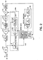
- Fig. 2 is a high level block diagram of an exemplary embodiment of a down conversion system.
- the down conversion system includes a variable length decoder (VLD) 210, a run-length (R/L) decoder 212, an inverse quantizer 214, and an inverse discrete cosine transform (IDCT) processor 218.
- VLD variable length decoder
- R/L run-length
- IDCT inverse discrete cosine transform
- the down conversion system includes a down conversion filter (DCT filter) 216 and down sampling processor 232 for filtering of encoded pictures. While the following describes the exemplary embodiment for a Main Profile, High Level encoded input, the down conversion system may be implemented with any similarly encoded high resolution image bit stream.
- DCT filter down conversion filter
- the down conversion system also includes a motion vector (MV) translator 220, a high resolution motion block generator 224 including up-sampling processor 226 and half-pixel generator 228 and a reference frame memory 222.
- MV motion vector
- the system includes a display conversion block 280 including a vertical programmable filter (VPF) 282 and horizontal programmable filter (HZPF) 284.
- the display conversion block 280 converts downsampled images into images for display on a particular display having a lower resolution.
- the down conversion filter 216 performs a lowpass filtering of the high resolution (e.g. Main Profile, High Level DCT) coefficients in the frequency domain.
- the down sampling processor 232 eliminates spatial pixel values by decimation of the lowpass filtered Main Profile, High Level picture to produce a set of pixel values which can be displayed on a monitor having lower resolution than that required to display a Main Profile, High Level picture.
- the exemplary reference frame memory 222 stores the spatial pixel values corresponding to at least one previously decoded reference frame having a resolution corresponding to the down-sampled picture.
- the MV translator 220 scales the motion vectors for each block of the received picture consistent with the reduction in resolution
- the low resolution motion block generator 224 receives the decimated low resolution motion blocks provided by the reference frame memory 222, up-samples these motion blocks and generates half pixel values to provide motion blocks at the half pixel accuracy which exhibit good spatial correspondence to the decoded and filtered differential pixel blocks.
- VLD 210 The Main Profile, High Level bit-stream is received and decoded by VLD 210.
- the VLD 210 provides DCT coefficients for each block and macroblock, and motion vector information.
- the DCT coefficients are run length decoded in the R/L decoder 212 and inverse quantized by the inverse quantizer 214.
- the VLD 210 and R/L decoder 212 correspond to the entropy decoder 110 of Fig. 1.
- the DCT coefficients of each block are lowpass filtered before decimation of the high resolution video image.
- the inverse quantizer 214 provides the DCT coefficients to the DCT filter 216 which performs a lowpass filtering in the frequency domain by weighting the DCT coefficients with predetermined filter coefficient values before providing them to the IDCT processor 218. In an exemplary embodiment, this filter operation is performed on a block by block basis.
- the IDCT processor 218 provides spatial pixel values by performing an inverse discrete cosine transform of the filtered DCT coefficients.
- the down sampling processor 232 reduces the picture sample size by eliminating spatial pixel sample values according to a predetermined decimation ratio; therefore, storing the lower resolution picture uses a smaller frame memory 222 compared to that which would be needed to store the higher resolution Main Profile, High Level picture.
- the DCT coefficients of the current received image represent the DCT coefficients of the residual components of the predicted image macroblocks.
- the predicted image macroblocks can be forward, backward, and bi-directionally predicted. In a bi-directional case, for example, a forward predicted image macroblock and a backward predicted image macroblock may be averaged to provide the bi-directionally predicted image macroblock.
- the horizontal components of the motion vectors for a predicted frame are scaled since the down sampled low resolution reference pictures of previous frames stored in memory do not have the same number of pixels as the high resolution predicted frame (Main Profile, High Level).
- the motion vectors of the Main Profile, High Level bit stream provided by the VLD 210 are provided to the MV translator 220.
- Each motion vector is scaled by the MV translator 220 to reference the appropriate prediction block of the reference frame of a previous image stored in reference frame memory 222.
- the size (number of pixel values) in the retrieved block is smaller than a block of the corresponding high resolution block used to encode the current image; consequently, the retrieved block is up-sampled to form a prediction block having the same number of pixels as the residual block provided by the IDCT processor 218.
- the forward or backward prediction block is up-sampled by the up-sampling processor 226 responsive to a control signal from the MV translator 220 to generate a block corresponding to the original high resolution block of pixels. Then, half pixel values are generated, if indicated by the motion vector for the up-sampled prediction block in the half-pixel generator 228, to ensure proper spatial alignment of the prediction block.
- the forward and backward predicted image macroblocks of upsampled pixels may be averaged to provide a bi-directionally predicted image macroblock.
- the up-sampled and aligned prediction block is added in adder 230 to the current filtered block, which is, for this example, the reduced resolution residual component from the predicted block.
- the display conversion block 280 adjusts the image for display on a low resolution television display by filtering the vertical and horizontal components of the downsampled image in the VPF 282 and the HZPF 284 respectively.
- the received motion vectors pointing to these frames may also be translated according to the conversion ratio.
- the following describes the motion translation for the luminance block, for example, in the horizontal direction.
- Dx as the horizontal decimation factor
- mv x as the half pixel horizontal motion vector of the original image frame
- the address of the top left pixel of the motion block in the original image frame, denoted as XH in the half pixel unit, is given by (1): XH 2x + mv x
- the pixel corresponding to the motion block starts in the down-sampled image, whose address is denoted as x* and y* in the pixel unit given in (2).
- x • XH 2 ⁇ Dx ;
- y* y
- the exemplary DCT filter 216 and down sampling processor 232 only reduce the horizontal components of the image, the vertical component of the motion vector is not affected.
- the motion vector is a half of a luminance motion vector in the original picture. Therefore, definitions for translating the chrominance motion vector may also use the two equations (1) and (2).
- Motion prediction is done by a two step process: first, pixel accuracy motion estimation in the original image frame restored by up-sampling the down-sampled image frame in the up-sampling processor 226 of Fig. 2, then the half-pixel generator 228 performs a half pixel motion estimation by averaging of nearest pixel values.
- Subpixels in a decimated picture which correspond to pixels in an original pixture, are interpolated, for example, using an up-sampling polyphase filter in the up-sampling processor 226, which gives a motion prediction in the original picture.
- the motion prediction is added in adder 230 to an output of the IDCT processor 218. Since the output values of the adder 230 correspond to an image in the upsampled original picture format, these values may be downsampled for display on a display having a lower resolution.
- Downsampling in the down sampling processor 232 is substantially equivalent to subsampling of an image frame, but adjustments may be made based upon the conversion ratio. For example, in the case of 3:1 downsampling, the number of horizontally downsampled pixels are 6 or 5 for each input macroblock, and the first downsampled pixels are not always the first pixel in the input macroblock.
- subpixel accuracy in motion block prediction is desirable in the down sampled picture. For example, using 3:1 decimation, it is desirable to have 1/3 (or 1/6) subpixel accuracy in the motion prediction.
- the subpixel which is a first pixel required by the motion vector, in addition to the down-sampled motion block, is determined.
- subsequent subpixel positions are determined using modulo arithmetic as described in the following.
- Fig. 3A shows subpixel positions and corresponding 17 predicted pixels for the 3:1 and 2:1 examples, and Table 1 gives the legend for Fig. 3A. Symbol Pixel ⁇ Downsampled Pixel ⁇ Upsampled Pixel ⁇ Prediction Pixel Extra Right and Left Pixels for Upsampling
- the up-sampling filters may be up-sampling polyphase filters, and Table 2A gives characteristics of these up-sampling polyphase interpolation filters. 3:1 Up-sampling 2:1 Up-sampling Number of Polyphase Filters 3 2 Number of Taps 3 5 Maximum number of horizontal downsampled pixels 9 13
- Tables 2B and 2C below, show exemplary polyphase filter coefficients for the exemplary 3:1 and 2:1 up-sampling polyphase equi-ripple filters.
- section II.C. discloses a comparison of motion tracking characteristics between equi-ripple, bi-linear, and Lagrangian upsampling filters.
- the numbers in parenthesis of Table 2B and Table 2C are 2's complement representations in 9 bits with the corresponding double precision numbers on the left.
- one corresponding phase of the polyphase interpolation filter is used.
- more pixels on the left and right are needed to interpolate 17 horizontal pixels in the downsampled image frame.
- 9 horizontal pixels are needed to produce the corresponding motion prediction block values because an up-sampling filter requires more left and right pixels outside of the boundary for the filter to operate.
- Fig. 3B summarizes the up-sampling process which is performed for each row of an input macroblock.
- step 310 the motion vector for the block of the input image frame being processed is received.
- step 312 the motion vector is translated to correspond to the downsampled reference frame in memory.
- step 314 the scaled motion vector is used to retrieve the coordinates of the prediction block stored in frame memory.
- step 316 the subpixel point for the block is determined and the initial polyphase filter values for up-sampling are then retrieved at step 318.
- the identified pixels for the prediction block of the stored downsampled reference frame are then retrieved from memory at step 320.
- the registers are initialized at step 322, which for the exemplary embodiment entails loading the registers with the initial 3 or 5 pixel values. Then, after filtering step 324, the process determines at step 326 whether all pixels have been processed. In the exemplary embodiment 17 pixels are processed. If all pixels have been processed, the up-sampled block is complete. If all pixels have not been processed, the phase is updated at step 328, and the phase is checked, for the 0 value. If the phase is not zero, the registers must be updated for the next set of polyphase filter coefficients. Updating registers step 332 then simply updates the input pixels. In an exceptional case where the left-most pixel is outside of the block boundary, a previous pixel value may be repeated.
- the up-sampling processor 226 retrieves a block of down sampled pixels from the reference frame memory 222.
- the up-sampling processor 226 uses interpolation to generate pixels to provide a prediction block. This results in a prediction block with the same number of pixels as the reduced resolution residual block to which it is added in the adder 230.
- the output of the adder 230 is then down sampled by the down sampling processor 232, stored in the reference frame memory 222, and then up sampled by the up-sampling processor 226 to generating the next prediction block. This cycle is repeated for each predicted frame, both P-frames and B-frames.
- image distortion is introduced by the up-sampling processor 226, this image distortion is also cycled through this process.
- the image distortion may be accumulated by the up-sampling processor 226 during each cycle. If many consecutive predicted frames are coded between intra-coded frames, this distortion may be amplified to the point where it becomes visible.
- a source of such image distortion may be poor motion tracking characteristics of the up-sampling processor 226.
- an up sampling filter in a down conversion system has both smooth low pass filtering and good motion tracking characteristics.
- the motion tracking property may take precedence over the low pass filtering to prevent visible motion jerkiness in a reproduced image.
- Fig. 4 shows the frequency response (dB vs. frequency, where ⁇ corresponds to half of the sampling frequency) of three different upsampling filters in a 3:1 horizontal down conversion system: an equi-ripple filter frequency response 410, a bi-linear filter frequency response 430, and a Lagrangian filter frequency response 420.
- the cutoff frequency 440 is equal to ⁇ /3 for the 3:1 decimation system ( ⁇ /2 for a 2:1 decimation system).
- the following example illustrates the motion tracking properties of these filters in a 3:1 down conversion system.
- These examples concern an image of a rectangular pulse moving one pixel per frame in the upsample domain.
- the coding structure consists of all forward predicted frames after an intra-frame. The image is interpolated based on every third pixel since the other pixels were thrown out during down sampling.
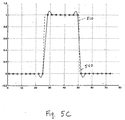
- Figs. 5A, 5B, and 5C show the interpolations 520, 530, 540 of the rectangular pulse by an equi-ripple filter, a bi-linear filter, and a third order Lagrangian filter, respectively.
- the dashed lines 510 (not visible in Fig. 5B) represent the rectangular pulse being interpolated.
- Lagrangian interpolation is well known to those skilled in the art and is taught by Atkinson, An Introduction to Numerical Analysis , 107-10 (1978), which is incorporated herein by reference.
- the equi-ripple filter interpolation 520 has the most overshoot and undershoot in comparison to the Lagrangian filter interpolation 540 and the bi-linear filter interpolation 530.
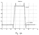
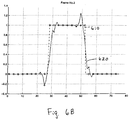
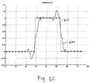
- Figs. 6A, 6B, 6C, 6D, 6E, and 6F illustrate equi-ripple filter interpolations of the moving (one pixel per frame) rectangular pulse in predicted frame numbers 1, 2, 3, 5, 8 and 10, respectively.
- the dashed lines 610 in Figs. 6A-6F represent the original image.
- the solid lines 620 in Figs. 6A-6F represent the equi-ripple interpolations of the downsampled original image 610.
- frame number 5 shown in Fig. 6D the interpolated pulse 620 is distorted and has moved ahead of the original pulse 610.
- frame number 10 shown in Fig. 6F the interpolated pulse 620 is even further ahead of the original pulse 610 than in frame number 5 shown in Fig. 6D.
- the difference between the interpolated pulse 620 in Fig. 6F and the original pulse 610 will result in a "snapping back" problem. This is caused when the interpolated image in the predicted frames moves ahead of the motion of the original image and is then followed by an accurately represented intra-coded frame. Since the motion of edges in predicted frames are ahead of the motion of the original image, the next intra-coded frame may give a viewer the impression that the motion is now going backward.
- the "snapping back" problem may result in the person's head “snapping back" to the right at every intra-coded frame when an equi-ripple filter of the above example is used for up-sampling.
- the severity of this type of distortion depends on the actual coding structure. For example, when applied to an IBBP coding structure, which has two Bi-directional frames between reference frames, the artifact is less noticable than in the example provided with reference to Figs. 6A-6F where there were 10 consecutive forward predicted frames.
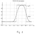
- Figs. 7 and 8 show images interpolated using Lagrangian and Bi-linear interpolators, respectively, for predicted frame number 10 under the same conditions as in Fig. 6F for an equi-ripple interpolator.
- the Lagrangian interpolation 720 in Fig. 7 and the Bi-linear interpolation 820 in Fig. 8 provide better motion tracking since their interpolated pulses 720, 820 are comparatively less ahead of the original image 610.
- Overshoot and undershoot are factors to consider when analyzing the predicted pulse distortion.
- the equi-ripple interpolation 620 of Fig. 6F has 16% over/undershoot
- the third order Lagrangian interpolation 720 of Fig. 7 has 6% over/undershoot
- the bi-linear interpolation 820 of Fig. 8 has no over/undershoot.
- a bi-linear filter or a Lagrangian filter is used in up-sampling processor 226.
- a Lagrangian filter is used in up-sampling processor 226.
- the third order Lagrangian filter has a better frequency response compared to a bilinear filter (as shown in Fig. 4) and has less over/undershoot than an equi-ripple filter (as shown by comparing Figs. 6F and 7).
- a bilinear filter is the same as a first order Lagrangian filter.
- a Lagrangian interpolator which is a polynomial interpolation for giving data points, may be designed as follows.
- the first order Lagrangian interpolator is a bilinear.
- the second order Lagrangian interpolator P 2 (x) and the third order Lagrangian interpolator P 3 (x) shown below may be derived from the above equations.
- Table 8 shows the Lagrangian filter coefficients for a 3:1 upsampling filter.
- phase 0 means integer pixel
- phase 1 means a half pixel in the 2:1 case and one third point between pixels in the 3:1 case
- phase 2 means two third point between pixels in the 3:1 case.
- input pixels are shifted for filtering at phase 0, but in the 3:1 case input shifting does not always occur at phase 0.
- the up-sampling processor 226 uses the third order Lagrangian filter for interpolation of a down-sampled image. This results in a balance between the motion tacking characteristics and the low pass filtering response.
- the 4 th order filter may have a better frequency response than the 3 rd order filter but the 3 rd order filter has better motion tracking characteristics.
- this particular design balances these factors and makes a tradeoff between them.
- the coding structure of a particular system determines where this balance should fall.
- the exemplary embodiment of the down conversion system includes the DCT filter 216 processing the DCT coefficients in the frequency domain, which replaces a lowpass filter in the spatial domain.
- DCT domain filtering instead of spatial domain filtering for DCT coded pictures, such as contemplated by the MPEG or JPEG standards.
- a DCT domain filter is computationally more efficient and requires less hardware than a spatial domain filter applied to the spatial pixels.
- a spatial filter having N taps may use as many as N multiplications and additions for each spatial pixel sample value. This compares to only one multiplication in the DCT domain filter.
- the simplest DCT domain filter is a truncation of the high frequency DCT coefficients.
- truncation of high frequency DCT coefficients does not result in a smooth filter and has drawbacks such as "ringing" near edges in the decoded picture.
- the DCT domain lowpass filter of the exemplary embodiment of the invention is derived from a block mirror filter in the spatial domain.
- the filter coefficient values for the block mirror filter are, for example, optimized in the spatial domain, and these values are then converted into coefficients of the DCT domain filter.
- DCT domain filtering can be done in either the horizontal or the vertical direction or both by combining horizontal and vertical filters.
- One exemplary filter of the present invention is derived from two constraints: first, the filter processes image data on a block by block basis for each block of the image without using information from other blocks of the same picture or from previous pictures; and second, the filter reduces visibility of block boundaries which occur when the filter processes boundary pixel values.
- an exemplary embodiment of the present invention implements a DCT domain filter which only processes blocks of the currently received picture.
- the filter is simply applied to a block of spatial pixel values, there is a transition of filtering on the block boundary which is caused by an insufficient number spatial pixel values beyond the boundary to fill the residual of the filter. That is to say, the edge of a block cannot be properly filtered because the N-tap filter has respective input pixels for only N/2 or for (N/2)-1 taps depending upon whether N is even or odd. The remaining input pixels are beyond the boundary of the block.
- the following describes an exemplary embodiment which implements a horizontal block mirror filter that lowpass filters 8 input spatial pixel sample values of a block. If the size of the input block is an 8 X 8 block matrix of pixel sample values, then a horizontal filtering can be done by applying the block mirror filter to each row of 8 pixel sample values. It will be apparent to one skilled in the art that the filtering process can be implemented by applying the filter coefficients columnwise of the block matrix, or that multidimensional filtering may be accomplished by filtering of the rows and then filtering the columns of the block matrix.
- a block mirror filter in the spatial domain can be equivalently implemented in the DCT domain by weighting DCT coefficients, as taught by Kim et. al., "DCT Domain Filter for ATV Down Conversion", IEEE Trans. on Consumer Electronics, Vol. 43 (4) 1074-8 (1997).
- Fig. 4 shows the correspondence between the input pixel values x 0 through x 7 (group X0) for an exemplary mirror filter for 8 input pixels which employs a 15 tap spatial filter represented by tap values h 0 through h 14 .
- the input pixels are mirrored on the left side of group X0, shown as group X1, and on the right side of group X0, shown as group X2.
- the output pixel value of the filter is the sum of 15 multiplications of the filter tap values with the corresponding pixel sample values.
- Fig. 4 illustrates the multiplication pairs for the first and second output pixel values.
- One embodiment of the exemplary block mirror filtering of the present invention is derived as by the following steps: 1) a one dimensional lowpass symmetric filter is chosen with an odd number of taps, which is less than 2N taps; 2) the filter coefficients are increased to 2N values by padding with zero's; 3) the filter coefficients are rearranged so that the original middle coefficient goes to the zeroth position by a left circular shift; 4) the DFT coefficients of the rearranged filter coefficients are determined; 5) the DCT filter coefficients are multiplied with the real number DFT coefficients of the input block; and 6) the inverse discrete cosine transform (IDCT) of the filtered DCT coefficients is performed by multiplying by IDCT coefficients to provide a block of lowpass-filtered pixels prepared for decimation.
- IDCT inverse discrete cosine transform
- the cutoff frequency of the lowpass filter is determined by the decimation ratio.
- the cutoff frequency is ⁇ /3 for a 3:1 decimation and ⁇ /2 for a 2:1 decimation, where ⁇ corresponds to half of the sampling frequency.
- a DCT domain filter in MPEG and JPEG decoders allows memory requirements to be reduced because the inverse quantizer and IDCT processing of blocks already exists in the decoder of the prior art, and only the additional scalar multiplication of DCT coefficients by the DCT domain filter coefficients is required. Therefore, a separate DCT domain filter block multiplication is not physically required in a particular implementation; another embodiment of the present invention simply combines the DCT domain filter coefficients with the IDCT processing coefficients.
- Table 4 shows the DCT block mirror filter (weighting) coefficients; in Table 4 the numbers in the parenthesis are 10 bit 2's complementary representations.
- the "*" of Table 4 implies an out of bound value for the 10 bit 2's complement representation because the value is more than 1; however, as is known by one skilled in the art, the multiplication of the column coefficients of the block by the value indicated by the * can be easily implemented by adding the coefficient value to the coefficient multiplied by the fractional value (remainder) of the filter value.
- These horizontal DCT filter coefficients weight each column in the block of 8 X 8 DCT coefficients of the encoded video image. For example, the DCT coefficients of column zero are weighted by H[0], and the DCT coefficients of first column is weighted by H[1] and so on.
- a two-dimensional DCT can be implemented as a one dimensional DCT performed on the columns of the input sequence, and then a second one dimensional DCT performed on the rows of the DCT processed input sequence.
- a two-dimensional IDCT can be implemented as a single process.
- Fig. 5A shows the input and decimated output pixels for 4:2:0 chrominance type for 3:1 decimation.
- Fig. 5B shows the input and decimated output pixels for 4:2:0 chrominance type 2:1 decimation.
- Table 5 gives the legend identification for the Luminance and Chrominance pixels of Fig. 5A and Fig. 5B. The pixel positions before and after the down conversion of Figs.
- 5A and 5B are the interlaced (3:1 decimation) and progressive (2:1 decimation) cases respectively Symbol Pixel + Luminance Before Decimation X Chrominance Before Decimation ⁇ Luminance After decimation ⁇ Chrominance After Decimation
- MB0 there are 6 down-sampled pixels horizontally, but 5 pixels in MB1 and MB2. These three MB types are repeating, therefore Modulo 3 arithmetic is to be applied.
- Table 6 summarizes the number of downsampling pixels and offsets for each input macroblock MB0, MB1, MB2.
- MB0 MB1 MB2 No. of Down Sampled Luminance Pixels 6 5 5 No. of Down Sampled Chrominance Pixels 3 3 2 Offset of 1st Down Sampled Luminance Pixel 0 2 1 Offset of 1st Down Sampled Chrominance Pixel 0 1 2
- the signal is subsampled for every second sample horizontally.
Landscapes
- Engineering & Computer Science (AREA)
- Multimedia (AREA)
- Signal Processing (AREA)
- Physics & Mathematics (AREA)
- General Physics & Mathematics (AREA)
- Theoretical Computer Science (AREA)
- Compression Or Coding Systems Of Tv Signals (AREA)
- Television Systems (AREA)
Applications Claiming Priority (2)
| Application Number | Priority Date | Filing Date | Title |
|---|---|---|---|
| US09/169,297 US6618443B1 (en) | 1997-03-12 | 1998-10-09 | Upsampling filter for a down conversion system |
| US169297 | 1998-10-09 |
Publications (2)
| Publication Number | Publication Date |
|---|---|
| EP0993195A2 true EP0993195A2 (de) | 2000-04-12 |
| EP0993195A3 EP0993195A3 (de) | 2001-08-22 |
Family
ID=22615075
Family Applications (1)
| Application Number | Title | Priority Date | Filing Date |
|---|---|---|---|
| EP99117484A Withdrawn EP0993195A3 (de) | 1998-10-09 | 1999-09-10 | Aufwartsabtasterfilter für ein Abwärtsumsetzungssystem |
Country Status (6)
| Country | Link |
|---|---|
| US (1) | US6618443B1 (de) |
| EP (1) | EP0993195A3 (de) |
| JP (1) | JP2000156858A (de) |
| KR (1) | KR100667606B1 (de) |
| CN (1) | CN1135840C (de) |
| CA (1) | CA2281436A1 (de) |
Cited By (1)
| Publication number | Priority date | Publication date | Assignee | Title |
|---|---|---|---|---|
| WO2011124254A1 (en) * | 2010-04-07 | 2011-10-13 | Linear Algebra Technologies Limited | Broadcast video decoder with reduced memory and processing requirements suitable for handheld and mobile applications |
Families Citing this family (30)
| Publication number | Priority date | Publication date | Assignee | Title |
|---|---|---|---|---|
| DE60033443D1 (de) * | 2000-06-23 | 2007-03-29 | St Microelectronics Asia | Universaler abtastratenumwandler für digitale audiofrequenzen |
| KR100421001B1 (ko) * | 2001-02-20 | 2004-03-03 | 삼성전자주식회사 | 샘플링 레이트 변환 장치 및 방법 |
| US20030021347A1 (en) * | 2001-07-24 | 2003-01-30 | Koninklijke Philips Electronics N.V. | Reduced comlexity video decoding at full resolution using video embedded resizing |
| US6983017B2 (en) * | 2001-08-20 | 2006-01-03 | Broadcom Corporation | Method and apparatus for implementing reduced memory mode for high-definition television |
| KR100513042B1 (ko) * | 2003-10-29 | 2005-09-06 | 한국전자통신연구원 | 지상파 디지털 텔레비젼 방송 시스템에서 동일채널중계기의 시간지연을 줄이기 위한 변조 장치 |
| KR100691285B1 (ko) * | 2004-01-19 | 2007-03-12 | 한국전자통신연구원 | 동일채널 중계기의 변조장치 및 그 방법 |
| JP2006243043A (ja) * | 2005-02-28 | 2006-09-14 | Sanyo Electric Co Ltd | 高域補間装置及び再生装置 |
| MX2007012653A (es) * | 2005-04-13 | 2007-12-13 | Thomson Licensing | Codificacion de luma-croma con uno o mas pronosticadores espaciales distintos. |
| KR100759224B1 (ko) * | 2005-12-14 | 2007-09-17 | 주식회사 대우일렉트로닉스 | 디스플레이 장치의 영상 표시방법 |
| US7460133B2 (en) * | 2006-04-04 | 2008-12-02 | Sharp Laboratories Of America, Inc. | Optimal hiding for defective subpixels |
| US8229234B2 (en) * | 2006-11-24 | 2012-07-24 | Nec Corporation | Coding and decoding device, coding and decoding method and program |
| US8832290B2 (en) * | 2007-02-23 | 2014-09-09 | Microsoft Corporation | Smart pre-fetching for peer assisted on-demand media |
| US7889949B2 (en) * | 2007-04-30 | 2011-02-15 | Microsoft Corporation | Joint bilateral upsampling |
| CN101442297B (zh) * | 2007-11-23 | 2011-06-08 | 深圳Tcl工业研究院有限公司 | 一种数字抽取滤波器 |
| US8270466B2 (en) * | 2008-10-03 | 2012-09-18 | Sony Corporation | Adaptive decimation filter |
| US8310592B2 (en) * | 2008-10-10 | 2012-11-13 | Panasonic Corporation | Signal processing apparatus, signal processing method, and program for signal processing |
| US8339512B2 (en) * | 2009-03-05 | 2012-12-25 | Sony Corporation | Method and apparatus for enhancement of high-definition video content |
| JP5700968B2 (ja) * | 2010-07-16 | 2015-04-15 | キヤノン株式会社 | 画像処理装置、画像処理方法、およびプログラム |
| CN102378011B (zh) * | 2010-08-12 | 2014-04-02 | 华为技术有限公司 | 一种图像上采样的方法、装置和系统 |
| CN107172424B (zh) | 2011-03-30 | 2020-04-14 | Lg 电子株式会社 | 环路滤波方法及其设备 |
| WO2012169096A1 (ja) * | 2011-06-08 | 2012-12-13 | パナソニック株式会社 | 映像表示装置及び映像処理装置 |
| US8953907B2 (en) * | 2011-06-15 | 2015-02-10 | Marvell World Trade Ltd. | Modified bicubic interpolation |
| US8948248B2 (en) | 2011-07-21 | 2015-02-03 | Luca Rossato | Tiered signal decoding and signal reconstruction |
| WO2014015032A2 (en) * | 2012-07-19 | 2014-01-23 | Cypress Semiconductor Corporation | Touchscreen data processing |
| GB2496015B (en) * | 2012-09-05 | 2013-09-11 | Imagination Tech Ltd | Pixel buffering |
| US20140333669A1 (en) * | 2013-05-08 | 2014-11-13 | Nvidia Corporation | System, method, and computer program product for implementing smooth user interface animation using motion blur |
| US9299128B2 (en) * | 2013-05-23 | 2016-03-29 | Futurewei Technologies, Inc. | Delta interpolation for upsampling imaging solution |
| JP6409516B2 (ja) | 2014-11-13 | 2018-10-24 | 富士通株式会社 | ピクチャ符号化プログラム、ピクチャ符号化方法及びピクチャ符号化装置 |
| US20160170702A1 (en) * | 2014-12-12 | 2016-06-16 | Apple Inc. | Devices and methods of image-splitting for dual-layer high dynamic range displays |
| US10616583B2 (en) | 2016-06-30 | 2020-04-07 | Sony Interactive Entertainment Inc. | Encoding/decoding digital frames by down-sampling/up-sampling with enhancement information |
Family Cites Families (33)
| Publication number | Priority date | Publication date | Assignee | Title |
|---|---|---|---|---|
| US3997772A (en) | 1975-09-05 | 1976-12-14 | Bell Telephone Laboratories, Incorporated | Digital phase shifter |
| EP0201148B1 (de) | 1980-04-11 | 1992-12-23 | Ampex Corporation | Vordezimierungsfilter für Bildveränderungssystem |
| US4472785A (en) | 1980-10-13 | 1984-09-18 | Victor Company Of Japan, Ltd. | Sampling frequency converter |
| WO1982003741A1 (en) | 1981-04-10 | 1982-10-28 | Bennett Phillip Patrick | System for spatially transforming images |
| DE3177088D1 (en) | 1981-04-10 | 1989-09-21 | Ampex | Controller for system for spatially transforming images |
| JPS58219841A (ja) | 1982-06-15 | 1983-12-21 | Kokusai Denshin Denwa Co Ltd <Kdd> | 標本化周波数の高速変換回路 |
| US4652908A (en) | 1985-03-25 | 1987-03-24 | Rca Corporation | Filtering system for processing a reduced-resolution video image |
| JP2592810B2 (ja) | 1986-09-30 | 1997-03-19 | 株式会社東芝 | サンプルレート変換回路 |
| US4774581A (en) | 1987-04-14 | 1988-09-27 | Rca Licensing Corporation | Television picture zoom system |
| US5057911A (en) | 1989-10-19 | 1991-10-15 | Matsushita Electric Industrial Co., Ltd. | System and method for conversion of digital video signals |
| US5367334A (en) | 1991-05-20 | 1994-11-22 | Matsushita Electric Industrial Co., Ltd. | Video signal encoding and decoding apparatus |
| JP2634971B2 (ja) | 1991-06-27 | 1997-07-30 | 住友ゴム工業株式会社 | 空気入りタイヤ |
| JP3255179B2 (ja) | 1992-02-14 | 2002-02-12 | ソニー株式会社 | データ検出装置 |
| GB2264417B (en) | 1992-02-17 | 1995-12-06 | Sony Broadcast & Communication | Video standards conversion |
| US5262854A (en) | 1992-02-21 | 1993-11-16 | Rca Thomson Licensing Corporation | Lower resolution HDTV receivers |
| JPH05283978A (ja) | 1992-03-31 | 1993-10-29 | Sony Corp | サンプリングレート変換装置 |
| US5331346A (en) | 1992-10-07 | 1994-07-19 | Panasonic Technologies, Inc. | Approximating sample rate conversion system |
| US5274372A (en) | 1992-10-23 | 1993-12-28 | Tektronix, Inc. | Sampling rate conversion using polyphase filters with interpolation |
| JP3093494B2 (ja) | 1992-11-18 | 2000-10-03 | 株式会社東芝 | 多様性信号処理装置 |
| US5614952A (en) | 1994-10-11 | 1997-03-25 | Hitachi America, Ltd. | Digital video decoder for decoding digital high definition and/or digital standard definition television signals |
| US5477397A (en) | 1993-02-23 | 1995-12-19 | Matsushita Electric Corporation Of America | Digital high definition television receiver with features that facilitate trick-play modes on a digital VCR |
| EP0719478B1 (de) | 1993-09-13 | 1998-07-22 | Analog Devices, Inc. | Digital-analog-wandlung mit nicht-uniformen abtastraten |
| US5483474A (en) | 1993-11-15 | 1996-01-09 | North Shore Laboratories, Inc. | D-dimensional, fractional bandwidth signal processing apparatus |
| US5613084A (en) | 1994-10-04 | 1997-03-18 | Panasonic Technologies, Inc. | Interpolation filter selection circuit for sample rate conversion using phase quantization |
| US5828421A (en) * | 1994-10-11 | 1998-10-27 | Hitachi America, Ltd. | Implementation efficient digital picture-in-picture decoding methods and apparatus |
| US5528301A (en) | 1995-03-31 | 1996-06-18 | Panasonic Technologies, Inc. | Universal video format sample size converter |
| CN1140126C (zh) | 1995-06-29 | 2004-02-25 | 汤姆森多媒体公司 | 分层压缩视频数据的编解码系统 |
| US5737019A (en) | 1996-01-29 | 1998-04-07 | Matsushita Electric Corporation Of America | Method and apparatus for changing resolution by direct DCT mapping |
| JP2000514987A (ja) | 1997-03-12 | 2000-11-07 | 松下電器産業株式会社 | Hdtvダウン変換システムのためのアップサンプリングフィルタおよび半画素生成器 |
| US6175592B1 (en) | 1997-03-12 | 2001-01-16 | Matsushita Electric Industrial Co., Ltd. | Frequency domain filtering for down conversion of a DCT encoded picture |
| US6141456A (en) * | 1997-12-31 | 2000-10-31 | Hitachi America, Ltd. | Methods and apparatus for combining downsampling and inverse discrete cosine transform operations |
| US6249549B1 (en) * | 1998-10-09 | 2001-06-19 | Matsushita Electric Industrial Co., Ltd. | Down conversion system using a pre-decimation filter |
| US6487249B2 (en) | 1998-10-09 | 2002-11-26 | Matsushita Electric Industrial Co., Ltd. | Efficient down conversion system for 2:1 decimation |
-
1998
- 1998-10-09 US US09/169,297 patent/US6618443B1/en not_active Expired - Fee Related
-
1999
- 1999-09-07 CA CA002281436A patent/CA2281436A1/en not_active Abandoned
- 1999-09-10 EP EP99117484A patent/EP0993195A3/de not_active Withdrawn
- 1999-10-05 JP JP11284942A patent/JP2000156858A/ja not_active Withdrawn
- 1999-10-08 CN CNB991217101A patent/CN1135840C/zh not_active Expired - Fee Related
- 1999-10-09 KR KR1019990043652A patent/KR100667606B1/ko not_active Expired - Fee Related
Cited By (3)
| Publication number | Priority date | Publication date | Assignee | Title |
|---|---|---|---|---|
| WO2011124254A1 (en) * | 2010-04-07 | 2011-10-13 | Linear Algebra Technologies Limited | Broadcast video decoder with reduced memory and processing requirements suitable for handheld and mobile applications |
| US20130202040A1 (en) * | 2010-04-07 | 2013-08-08 | Linear Algebra Technologies Limited | Broadcast video decoder with reduced memory and processing requirements suitable for handheld and mobile applications |
| US9509994B2 (en) * | 2010-04-07 | 2016-11-29 | Linear Algebra Technologies Limited | Broadcast video decoder with reduced memory and processing requirements suitable for handheld and mobile applications |
Also Published As
| Publication number | Publication date |
|---|---|
| CN1255018A (zh) | 2000-05-31 |
| EP0993195A3 (de) | 2001-08-22 |
| CN1135840C (zh) | 2004-01-21 |
| KR100667606B1 (ko) | 2007-01-15 |
| CA2281436A1 (en) | 2000-04-09 |
| US6618443B1 (en) | 2003-09-09 |
| KR20000028961A (ko) | 2000-05-25 |
| JP2000156858A (ja) | 2000-06-06 |
Similar Documents
| Publication | Publication Date | Title |
|---|---|---|
| US6618443B1 (en) | Upsampling filter for a down conversion system | |
| US6487249B2 (en) | Efficient down conversion system for 2:1 decimation | |
| US6249549B1 (en) | Down conversion system using a pre-decimation filter | |
| EP0908057B1 (de) | Aufwärtsabtasterfilter und halbbildelementgenerator für abwärtsumsetzungssystem für hochauflösungsfernsehen | |
| US6175592B1 (en) | Frequency domain filtering for down conversion of a DCT encoded picture | |
| US6990241B2 (en) | Circuit and method for decoding an encoded version of an image having a first resolution directly into a decoded version of the image having a second resolution | |
| US7263231B2 (en) | Method and apparatus for performing video image decoding | |
| WO1998041012A9 (en) | Mpeg decoder providing multiple standard output signals | |
| US6993076B1 (en) | Apparatus and method for deriving an enhanced decoded reduced-resolution video signal from a coded high-definition video signal | |
| EP0973337A2 (de) | System zur Ableitung eines mit BESCHRÄNKTER AUFLÖSUNG dekodierten Videosignales aus einem Videosignal mit hoher Auflösung | |
| KR100563015B1 (ko) | Hdtv다운컨버젼시스템을위한업샘플링필터와하프-픽셀발생기 |
Legal Events
| Date | Code | Title | Description |
|---|---|---|---|
| PUAI | Public reference made under article 153(3) epc to a published international application that has entered the european phase |
Free format text: ORIGINAL CODE: 0009012 |
|
| AK | Designated contracting states |
Kind code of ref document: A2 Designated state(s): AT BE CH CY DE DK ES FI FR GB GR IE IT LI LU MC NL PT SE |
|
| AX | Request for extension of the european patent |
Free format text: AL;LT;LV;MK;RO;SI |
|
| PUAL | Search report despatched |
Free format text: ORIGINAL CODE: 0009013 |
|
| AK | Designated contracting states |
Kind code of ref document: A3 Designated state(s): AT BE CH CY DE DK ES FI FR GB GR IE IT LI LU MC NL PT SE |
|
| AX | Request for extension of the european patent |
Free format text: AL;LT;LV;MK;RO;SI |
|
| RIC1 | Information provided on ipc code assigned before grant |
Free format text: 7H 04N 7/26 A, 7H 04N 7/30 B, 7H 04N 7/36 B, 7H 04N 7/50 B, 7H 04N 7/01 B |
|
| 17P | Request for examination filed |
Effective date: 20020107 |
|
| AKX | Designation fees paid |
Free format text: DE FR GB |
|
| RAP1 | Party data changed (applicant data changed or rights of an application transferred) |
Owner name: PANASONIC CORPORATION |
|
| STAA | Information on the status of an ep patent application or granted ep patent |
Free format text: STATUS: THE APPLICATION IS DEEMED TO BE WITHDRAWN |
|
| 18D | Application deemed to be withdrawn |
Effective date: 20090401 |