EP0993237A2 - Verfahren zur Bestrahlung mit Licht - Google Patents
Verfahren zur Bestrahlung mit Licht Download PDFInfo
- Publication number
- EP0993237A2 EP0993237A2 EP99119142A EP99119142A EP0993237A2 EP 0993237 A2 EP0993237 A2 EP 0993237A2 EP 99119142 A EP99119142 A EP 99119142A EP 99119142 A EP99119142 A EP 99119142A EP 0993237 A2 EP0993237 A2 EP 0993237A2
- Authority
- EP
- European Patent Office
- Prior art keywords
- sub
- intensity
- illumination
- light
- illumination light
- Prior art date
- Legal status (The legal status is an assumption and is not a legal conclusion. Google has not performed a legal analysis and makes no representation as to the accuracy of the status listed.)
- Withdrawn
Links
Images


Classifications
-
- H—ELECTRICITY
- H05—ELECTRIC TECHNIQUES NOT OTHERWISE PROVIDED FOR
- H05B—ELECTRIC HEATING; ELECTRIC LIGHT SOURCES NOT OTHERWISE PROVIDED FOR; CIRCUIT ARRANGEMENTS FOR ELECTRIC LIGHT SOURCES, IN GENERAL
- H05B39/00—Circuit arrangements or apparatus for operating incandescent light sources
- H05B39/04—Controlling
- H05B39/041—Controlling the light-intensity of the source
- H05B39/044—Controlling the light-intensity of the source continuously
-
- H—ELECTRICITY
- H05—ELECTRIC TECHNIQUES NOT OTHERWISE PROVIDED FOR
- H05B—ELECTRIC HEATING; ELECTRIC LIGHT SOURCES NOT OTHERWISE PROVIDED FOR; CIRCUIT ARRANGEMENTS FOR ELECTRIC LIGHT SOURCES, IN GENERAL
- H05B41/00—Circuit arrangements or apparatus for igniting or operating discharge lamps
- H05B41/14—Circuit arrangements
- H05B41/36—Controlling
- H05B41/38—Controlling the intensity of light
- H05B41/39—Controlling the intensity of light continuously
- H05B41/392—Controlling the intensity of light continuously using semiconductor devices, e.g. thyristor
- H05B41/3921—Controlling the intensity of light continuously using semiconductor devices, e.g. thyristor with possibility of light intensity variations
- H05B41/3922—Controlling the intensity of light continuously using semiconductor devices, e.g. thyristor with possibility of light intensity variations and measurement of the incident light
-
- H—ELECTRICITY
- H05—ELECTRIC TECHNIQUES NOT OTHERWISE PROVIDED FOR
- H05B—ELECTRIC HEATING; ELECTRIC LIGHT SOURCES NOT OTHERWISE PROVIDED FOR; CIRCUIT ARRANGEMENTS FOR ELECTRIC LIGHT SOURCES, IN GENERAL
- H05B47/00—Circuit arrangements for operating light sources in general, i.e. where the type of light source is not relevant
- H05B47/10—Controlling the light source
-
- Y—GENERAL TAGGING OF NEW TECHNOLOGICAL DEVELOPMENTS; GENERAL TAGGING OF CROSS-SECTIONAL TECHNOLOGIES SPANNING OVER SEVERAL SECTIONS OF THE IPC; TECHNICAL SUBJECTS COVERED BY FORMER USPC CROSS-REFERENCE ART COLLECTIONS [XRACs] AND DIGESTS
- Y10—TECHNICAL SUBJECTS COVERED BY FORMER USPC
- Y10S—TECHNICAL SUBJECTS COVERED BY FORMER USPC CROSS-REFERENCE ART COLLECTIONS [XRACs] AND DIGESTS
- Y10S315/00—Electric lamp and discharge devices: systems
- Y10S315/04—Dimming circuit for fluorescent lamps
Definitions
- the present invention relates to a light irradiation method and a light irradiation system for increasing or decreasing a perceived brightness of a target, which is illuminated, by performing time-wise control of prescribed illumination light.
- walls of the room are illuminated to be brighter than the rest of the room, instead of uniformly illuminating the entirety of the inside of the room.
- the entirety of the inside of the room is perceived to be brighter at an equal energy consumption.
- a painting on the wall or a table in the room is spot-illuminated.
- the inside of the room is perceived to be brighter.
- a "sparkling" light emitting section which is small in size but has a high luminance is included in an illumination device, so that the inside of the room is perceived to be brighter.
- K. Hashimoto et al. "Visual Clarity and Feeling of Contrast", Color Res. Appl., Vol. 19-3, pp. 171-185 (1994)
- K. Hashimoto et al. "Method for evaluating the color rendering property of a light source based on the consciousness”
- the Journal of the Illuminating Engineering Institute of Japan, Vol. 79, No. 11, pp. 29-37 (1995) describe that a perceived brightness of an indoor target can be raised by utilizing the phenomenon that the colorfulness of a target is increased when illuminated with a lamp having a superior color rendering property.
- Ikeda et al. In a recent study performed by Ikeda et al., information obtained from various objects seen by an observer when he/she enters the room is referred to as "initial visual information", and illumination states of the inside of the room recognized based on the initial visual information including the brightness of the room is referred to as "illumination recognition visual space”. Ikeda et al. has studied physical factors which determine the initial visual information and the illumination recognition visual space.
- a main irradiation section forming a target and a sub irradiation section for providing sub illumination light to or from at least one of a background and a neighborhood of the target are provided, and a perceived brightness of the target is varied by performing time-wise control of an intensity of the sub illumination light emitted by the sub irradiation section.
- the main irradiation section is an illumination source for emitting main illumination light.
- a perceived brightness of the illumination source is decreased by increasing the intensity of the sub illumination light emitted by the sub irradiation section, and a perceived brightness of the illumination source is increased by decreasing the intensity of the sub illumination light emitted by the sub irradiation section.
- the time-wise control of the intensity of the sub illumination light may be performed so that a rate of change of the intensity is lower while the intensity is increasing than while the intensity is decreasing.
- the main irradiation section is an indication lamp for emitting a prescribed indication light.
- a perceived brightness of the indication lamp is decreased by increasing the intensity of the sub illumination light emitted by the sub irradiation section, and a perceived brightness of the indication lamp is increased by decreasing the intensity of the sub illumination light emitted by the sub irradiation section.
- the time-wise control of the intensity of the sub illumination light may be performed so that a rate of change of the intensity is lower while the intensity is increasing than while the intensity is decreasing.
- the main irradiation section is an image display section for displaying a prescribed image
- the target is the prescribed image
- a perceived brightness of the prescribed image is increased by increasing the intensity of the sub illumination light emitted by the sub irradiation section, and a perceived brightness of the prescribed image is decreased by decreasing the intensity of the sub illumination light emitted by the sub irradiation section.
- the prescribed image includes a content, a brightness of which is inherently changeable.
- a highest luminance of the sub illumination light is set to be equal to or less than a highest luminance of the target.
- the intensity of the sub illumination light may be increased and decreased repeatedly.
- the intensity of the sub illumination light may be varied in accordance with a sine waveform having a frequency of about 0.01 Hz or more and about 8 Hz or less.
- a minimum value of the intensity of the sub illumination light is larger than zero.
- the sub irradiation section is located at such a position that prevents an observer from viewing the sub irradiation section.
- the invention described herein makes possible the advantages of providing an illumination method for effectively changing (increasing and decreasing) a perceived brightness of a target by changing illumination conditions of the background or the neighborhood of the target without changing the amount of light directly illuminating the target.
- a perceived brightness of a target is influenced by a contrast thereof relative to the brightness of the background or neighborhood thereof.
- the present inventors studied the relationship between the illumination conditions in the background or neighborhood of the target and the perceived brightness of the target from various aspects. As a result, the present inventors confirmed that the perceived brightness of the target can be effectively changed (increased or decreased) by performing time-wise control of the illumination conditions in the background or neighborhood of the target, more specifically, an intensity of at least one of light illuminating the background or neighborhood of the target and light provided from the background or neighborhood of the target, without changing the amount of light directly illuminating the target.
- a light irradiation method (simply referred to as the "irradiation method” hereinbelow) according to the present invention is applied to an image display system.
- FIG. 1 is a schematic isometric view illustrating a structure of an image display system to which an irradiation method according to the present invention is applied.
- the image display system includes an image display device 1 and an illumination source 2 located behind the image display device 1 .
- an image 4 is displayed on a display section of the image display device 1, an image 4 is displayed.
- the background and the neighborhood of image display device 1 are illuminated with illumination light 5 directed from the illumination source 2 .
- the image display device 1 can be, for example, a CRT, and the illumination source 2 for emitting the illumination light 5 can be, for example, a straight type 40W fluorescent lamp.
- Figure 2 is a schematic view showing such an image display system viewed by an observer 3 ( Figure 1 ) positioned directly in front of the image display device 1 .
- the observer 3 observes the image display device 1 , the image 4 displayed on the display section of the image display device 1 , and the illumination light 5 in the background and the neighborhood of the image display device 1 emitted by the illumination source 2 located behind the image display device 1 .
- the observer 3 can not see the illumination source 2 .
- the image display device 1 is considered to be a main irradiation section
- the illumination source 2 for emitting the illumination light 5 to illuminate the background and the neighborhood of the image display device 1 is considered to be a sub irradiation section.
- a perceived brightness of the image 4 (i.e., target) displayed by the image display device 1 is varied by performing time-wise control of an intensity of the illumination light 5 emitted by the illumination source 2 (i.e., sub irradiation section).
- the mechanism of varying the perceived brightness in this manner is based on the following phenomenon which has been confirmed by the present inventors as a result of their studies.
- a highest luminance of the inside of the image 4 i.e., the luminance of the brightest pixel among a plurality of pixels forming the image 4
- a highest luminance of the illumination light 5 also referred to as "sub illumination light”
- the observer 3 perceives that the illumination in the background and the neighborhood of the image display device 1 obtained by the illumination light 5 is integrated with the illumination obtained from a content of the image 4 . Accordingly, when the intensity of the illumination light 5 is increased, the perceived brightness of the image 4 as the target is increased; and when the intensity of the illumination light 5 is decreased, the perceived brightness of the image 4 is decreased.
- the intensity of the illumination light 5 is increased or decreased in the range not exceeding the highest luminance of the image 4 ", the illumination light 5 is increased or decreased so that the highest luminance thereof is about 80% or more and 100% or less of the highest luminance of the image 4 .
- the value "80%” is based on the following report by Ikeda et al. on a series of experiments: In order to cause an observer of two rooms illuminated under different conditions located side by side to perceive continuity between the two rooms, the illuminance of one of the rooms needs to be set at 0.8 to 1.5 times the illuminance of the other room.
- the upper limit of "100% of the highest luminance of the image 4 " regarding the intensity of the illumination light 5 is an optimum value for providing an effect in this example.
- the observer 3 can perceive that the illumination in the background and the neighborhood of the image display device 1 obtained by the illumination light 5 is integrated with the illumination obtained from a content of the image 4 , and thus, the effect of this example can be provided so long as the highest luminance of the illumination light 5 is about 150% or less of the highest luminance of the image 4 .
- the lower limit of "80% of the highest luminance of the image 4 " also regarding the intensity of the illumination light 5 is an optimum value for providing the effect in this example.
- the highest luminance of the illumination light 5 can be lower than the above-mentioned lower limit so long as the observer can perceive a change (i.e., fluctuation) in the illumination.
- the observer 3 perceives that the illumination light 5 in an illumination environment in which the image 4 is observed is integrated with an illumination environment obtained from the unreal image 4 displayed by the image display device 1 . Accordingly, the observer 3 perceives a change in the brightness of the image 4 and also feels more strongly the sense of being at the site of the image 4 .
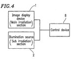
- an image display system to which an irradiation method according to the present invention is applied includes (1) an image display device, as a main irradiation section, for displaying an image as a target and (2) an illumination source, as a sub irradiation section, for providing a background or neighborhood of the target with the illumination light (the sub illumination light).
- an image display device as a main irradiation section
- an illumination source as a sub irradiation section
- a perceived brightness of the target can be increased by increasing the intensity of the illumination light emitted by the sub irradiation section, and the perceived brightness of the target can be decreased by decreasing the intensity of the illumination light emitted by the sub irradiation section.
- the image display device 1 as the main irradiation section may be any display device operating based on any display principle.
- the image display device 1 may be a PDP (plasma display panel), an LCD (liquid crystal display), a projector or any other display device instead of the CRT (cathode ray tube).
- the image display device 1 displays the image 4 at a relatively high luminance since, according to the present invention, (1) the background or neighborhood of the image 4 is illuminated by the illumination light 5 emitted by the illumination source 2 (the sub irradiation section), and (2) the range of change in the intensity of the illumination light 5 is determined by the highest luminance of the image 4.
- the illumination source 2 acting as the sub irradiation section for emitting the illumination light 5 may be any light emitting device operating based on any light emitting principle so long as the intensity of the light can be adjusted.
- the illumination source 2 may be an incandescent lamp, an LED, an EL element or any other light emitting device.
- the image 4 displayed by the image display device 1 can be classified into one of two categories of a still image and a moving image.
- the image 4 can be classified into one of two categories of an actual image and a CG image.
- the present inventors confirmed by experiments regarding a still actual image and a moving CG image that the perceived brightness of the image 4 can be varied (increased or decreased) and the image 4 can make the observer feel a sense of being at the site of the image 4 more strongly. Accordingly, the effect of the present invention applied to an image display system can be provided regardless of the type of the image.
- the above-described mistaken perception of the illumination environment is more easily induced in the case of a moving image than a still image and in the case of an actual image than a CG image.
- the reason for this is that a moving image and an actual image appear to be more real. Accordingly, the effect of the present invention is enhanced in the case of a still actual image than a still CG picture, and in the case of a moving CG image than a still actual image.
- the intensity of the illumination light 5 needs to be changed in association with the content of the image, which requires a different technology from the technology used in this example.
- the content of the image 4 is an important element for providing the effect according to the present invention .
- an image having a content which allows the observer to immediately perceive the illumination environment in the image is preferable for providing the effect of the present invention, because such an image allows the observer to perceive the integrity of the illumination environment of the image with the illumination environment of the background or neighborhood thereof, and also allows the observer to perceive a change in the illumination environment.
- the image 4 (even when it is a still image) includes such a content that a brightness thereof is inherently changeable.
- the observer 3 observing an object or light in the image 4 is led to have a mistaken perception that the brightness of the object or light in the image 4 is changing when the intensity of the illumination light 5 provided to the background or neighborhood of the image 4 by the illumination source 2 (the sub irradiation section) is varied.
- the observer 3 cannot have the above-mentioned mistaken perception unless the object or light in the image 4 can have a brightness inherently changeable (i.e., can be brightened or darkened).
- Examples of the object or light fulfilling such a condition include the object or light having a fluctuation (variation) in its brightness condition, such as sky, shade of a tree, beach illuminated by sunlight, candle light, and bonfire.
- the rate of change (increase or decrease) of the intensity of the illumination light 5 needs to be set so that the change is sufficiently perceivable by the observer 3 but does not cause the observer 3 to feel the light is uncomfortably flickering.
- the frequency of 8 Hz or less is preferable.
- the present inventors observed a change in the perceived brightness by varying the intensity of the illumination light 5 at different frequencies. A change in the perceived brightness was obtained most effectively when the intensity of the illumination light 5 was varied at about 0.2 Hz. When the intensity of the illumination light 5 was varied at about 0.01 Hz or less, the observer perceived that the change in the brightness was excessively dull, and thus the effect of a change in the perceived brightness was insufficient. As can be appreciated, the intensity of the illumination light 5 is preferably changed at a frequency in the range of about 0.01 Hz or more and about 8 Hz or less.
- the observer 3 can observe the image 4 (target) without caring about the change in the illumination light 5 . Accordingly, a smooth continuous change represented by a sine waveform as shown in Figure 3A is effective.
- the minimum value of the intensity of the illumination light 5 is preferably kept above zero in order to allow the observer 3 to observe the image 4 without caring about the change in the illumination light 5 .
- the waveform shown in Figure 3B is preferable.
- the effect of an increase in the perceived brightness is emphasized when, as shown in Figure 3B , the rate of change is higher while the intensity of the illumination light 5 is increasing and the rate of change is lower while the intensity is decreasing.
- the waveform shown in Figure 3C is preferable.
- the effect of a decrease in the perceived brightness is emphasized when, as shown in Figure 3C , the rate of change is higher while the intensity of the illumination light 5 is decreasing and the rate of change is lower while the intensity is increasing.
- the change in the intensity of the illumination light 5 does not need to be periodical.
- the illumination light 5 has a similar color to that of a part of the image 4 or has a color having low chroma similar to general illumination light.
- the illumination source 2 (the sub irradiation section) for providing illumination light 5 (the sub illumination light) to the background or neighborhood of the image 4 which is displayed by the image display device 1 (the main irradiation section) is located immediately behind the image display device 1 .
- the present invention is not limited to such an arrangement.
- the illumination source 2 may be located far from the image display device 1 so that the illumination light 5 is provided from a position far from the image display device 1.
- a structure in which the observer 3 cannot directly view the illumination source 2 is effective.
- the image display system can include a control device 8 .
- the intensity of the illumination light (the sub illumination light) provided by the illumination source 2 (the sub irradiation section) is changed in synchronization with the content of the image 4 (in Figure 2 ) displayed by the image display device 1 (the main irradiation section)
- the observer can perceive more strongly that the illumination environment obtained by the illumination light is integrated with the illumination environment obtained from the image 4 displayed by the image display device 1 .
- the observer feel more strongly the sense of being at the site of the image 4 .
- an irradiation method according to the present invention is applied to an illumination system.
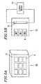
- Figure 5A is a schematic isometric view of an illumination section included in the illumination system to which an irradiation method according to the present invention is applied.
- Figure 5B is a schematic view of the illumination system.
- the illumination system includes an illumination section 20 acting as an illumination source, and the illumination section 20 includes a main illumination section (the main irradiation section) 9 and a sub illumination section (the sub irradiation section) 10.
- the main illumination section 9 includes a compact fluorescent lamp
- the sub illumination section 10 includes a straight type 20W fluorescent lamp. More specifically, the main illumination section 9 includes nine 27W compact fluorescent lamps arranged in an array of 3x3 with a gap of two adjacent fluorescent lamps being about 1 cm.
- the sub illumination section 10 includes four straight type 20W fluorescent lamps arranged parallel to each other (for illustrative purposes, only one among them is shown in Figure 5B ).
- the illumination system further includes a control section 11 for controlling the intensity of light provided by the sub illumination section 10 (i.e., the straight type 20W fluorescent lamps).
- the main illumination section 9 corresponds to a target and emits main illumination light.
- the sub illumination section 10 provides sub illumination light emitted from the background or neighborhood of the target.
- a perceived brightness of the main illumination section 9 viewed by an observer changes by performing time-wise control of the intensity of the sub illumination light provided by the sub illumination section 10. More specifically, when the intensity of the sub illumination light provided by the sub illumination section 10 is increased, the perceived brightness of the main illumination section 9 as the target is decreased because the contrast between the main illumination light provided by the main illumination section 9 and the sub illumination light provided by the sub illumination section 10 from the background or neighborhood is reduced. On the other hand, when the intensity of the sub illumination light provided by the sub illumination section 10 is decreased, the perceived brightness of the main illumination section 9 as the target is increased because the contrast between the main illumination light provided by the main illumination section 9 and the sub illumination light provided by the sub illumination section 10 from the background or neighborhood is raised.
- an efficient illumination system providing a satisfactorily bright illumination at low power consumption is realized by especially utilizing the effect of an increase in the perceived brightness of the main illumination section 9 .
- the perceived brightness is increased when the contrast between the light from the main illumination section 9 and the light from the sub illumination section 10 is raised by reducing the intensity of the sub illumination light.
- Such an increase is emphasized when the intensity of the sub illumination light is changed continuously, and more specifically when, as shown in Figure 3C, the rate of change is higher while the intensity is decreasing and the rate of change is lower while the intensity is increasing.
- Such a manner of adjusting the rate of change is effective for enhancing the effect of an increase in the perceived brightness of the main illumination section 9 .
- an illumination system to which an irradiation method according to the present invention is applied includes a main illumination section (the main irradiation section) acting as a target and emitting main illumination light and a sub illumination section (the sub irradiation section) for providing sub illumination light from the background or neighborhood of the main illumination section.
- a main illumination section acting as a target and emitting main illumination light
- a sub illumination section the sub irradiation section
- the illumination system By performing time-wise control of the intensity of the sub illumination light provided by the sub illumination section, the perceived brightness of the main illumination section as the target can be varied. Such a change is caused by a change in contrast between the main illumination light from the main illumination section and the sub illumination light from the sub illumination section.
- the perceived brightness of the main illumination section is increased by decreasing the intensity of the sub illumination section, and the perceived brightness of the main illumination section is decreased by increasing the intensity of the sub illumination section.
- the illumination system according to the present invention obtains an improved efficiency of providing a brighter illumination at lower power consumption
- the main illumination section 9 may be any light emitting device operating based on any light emitting principle so long as the intensity of the light can be adjusted.
- the main illumination section 9 may include an incandescent lamp, an LED, an EL element or any other light emitting element instead of the fluorescent lamps.
- the sub illumination section 10 may also be any light emitting device operating based on any light emitting principle so long as the intensity of the light can be adjusted.
- the sub illumination section 10 may include an incandescent lamp, an LED, an EL element or any other light emitting element instead of the fluorescent lamps.
- the number and the size of the light emitting elements included in the main illumination section 9 can be arbitrarily determined based on the use of the illumination system.
- the main illumination section 9 includes a single light emitting element (illumination lamp) instead of a plurality of light emitting elements as shown in Figure 5B, the contrast per unit area can be controlled more precisely and thus the effect of the present invention is more significant.
- the sub illumination section 10 is provided mainly for illuminating the background or neighborhood of the main illumination section 9 .
- the structure of the sub illumination section 10 is determined based on, for example, the number or size of the light emitting elements included in the main illumination section 9 . More specifically, the size of the sub illumination section 10 is larger than that of the main illumination section 9 , and the number of the light emitting elements included in the sub illumination section 10 is set so as to provide a substantially equal luminance to that of the main illumination section 9 .
- the size of the gap between the adjacent light emitting elements is related to the contrast between the light from the main illumination section 9 and the light from the sub illumination section 10 .
- the gap is excessively large as compared to the size of each light emitting element included in the main illumination section 9 , the area ratio of the main illumination section 9 with respect to the total size of the illumination section 20 is excessively small. Accordingly, the size of the gap is preferably set so that the contrast between the light from the main illumination section 9 and the light from the sub illumination section 10 is sufficiently perceived.
- the sub illumination section 10 for providing sub illumination light from the background or neighborhood of the main illumination section 9 is located immediately behind the main illumination section 9 .
- the present invention is not limited to such an arrangement.
- the sub illumination section 10 may be located far from the main illumination section 9 (e.g., the main illumination section 9 is located on a wall in the room and the sub illumination section 10 is located on an opposite wall), so that the sub illumination light is provided from a position far from the main illumination section 9 .
- the illumination system described in the second example can be used for various general uses including a system to be installed on the ceiling or the wall.
- the present invention is more effective when being applied to an indication system in which the main irradiation section emits a prescribed indication light indicating a certain information and the observer often directly observes (or looks at) the indication light intentionally.
- an indication system can be, for example, a signal lamp, a signal lamp for passengers, or a guiding lamp.
- a perceived brightness of a target can be effectively varied by performing time-wise control of at least one of illumination light directed toward the background or neighborhood of the target or illumination light provided from the background or neighborhood of the target (i.e., performing time-wise control of the illumination conditions in the background or neighborhood of the target) without changing the amount of light directly illuminating the target.
- an irradiation method according to the present invention When such an irradiation method according to the present invention is applied to an illumination system for providing an illumination light, or an indication system for emitting a prescribed indication light such as, for example, a signal lamp, the system obtains an improved efficiency of providing a brighter illumination light or a brighter indication light at lower power consumption, especially utilizing an increase in the perceived brightness of the target.
Landscapes
- Circuit Arrangement For Electric Light Sources In General (AREA)
- Liquid Crystal Display Device Control (AREA)
Applications Claiming Priority (2)
| Application Number | Priority Date | Filing Date | Title |
|---|---|---|---|
| JP28243998 | 1998-10-05 | ||
| JP28243998 | 1998-10-05 |
Publications (2)
| Publication Number | Publication Date |
|---|---|
| EP0993237A2 true EP0993237A2 (de) | 2000-04-12 |
| EP0993237A3 EP0993237A3 (de) | 2001-01-03 |
Family
ID=17652439
Family Applications (1)
| Application Number | Title | Priority Date | Filing Date |
|---|---|---|---|
| EP99119142A Withdrawn EP0993237A3 (de) | 1998-10-05 | 1999-10-05 | Verfahren zur Bestrahlung mit Licht |
Country Status (2)
| Country | Link |
|---|---|
| US (1) | US6285134B1 (de) |
| EP (1) | EP0993237A3 (de) |
Cited By (3)
| Publication number | Priority date | Publication date | Assignee | Title |
|---|---|---|---|---|
| WO2006059263A1 (en) * | 2004-11-30 | 2006-06-08 | Koninklijke Philips Electronics N.V. | Display system |
| WO2012004696A3 (en) * | 2010-07-06 | 2012-05-18 | Koninklijke Philips Electronics N.V. | Method and apparatus for illuminating |
| CN102972098A (zh) * | 2010-07-06 | 2013-03-13 | 皇家飞利浦电子股份有限公司 | 用于照明的方法和装置 |
Families Citing this family (3)
| Publication number | Priority date | Publication date | Assignee | Title |
|---|---|---|---|---|
| US20090251067A1 (en) * | 2008-04-02 | 2009-10-08 | Johnson Paul K | Pulsed led illumination to save energy |
| US8588576B2 (en) | 2010-02-26 | 2013-11-19 | Sharp Kabushiki Kaisha | Content reproduction device, television receiver, content reproduction method, content reproduction program, and recording medium |
| US8350481B1 (en) * | 2010-05-27 | 2013-01-08 | Harold Larsen | Method of creating a light effect |
Citations (4)
| Publication number | Priority date | Publication date | Assignee | Title |
|---|---|---|---|---|
| EP0348137A2 (de) * | 1988-06-22 | 1989-12-27 | Third Dimension Limited | Optisches Anzeigegerät |
| US4972305A (en) * | 1988-05-16 | 1990-11-20 | Blackburn R Geoffrey | Light image generating system |
| US5251392A (en) * | 1991-02-08 | 1993-10-12 | Vemco Corporation | Artificial window |
| US5265357A (en) * | 1992-01-22 | 1993-11-30 | Zhilong Yu | Magic 3D effect enhancing frame |
Family Cites Families (12)
| Publication number | Priority date | Publication date | Assignee | Title |
|---|---|---|---|---|
| IT1053342B (it) | 1975-02-22 | 1981-08-31 | Rodenstock Optik G | Apparecchio d esame oftalmico perimetrico |
| FR2603685B1 (fr) | 1986-09-04 | 1991-01-18 | Arnaud Annick | Procede d'animation de structures lumineuses et instrument de lumiere |
| US5012333A (en) | 1989-01-05 | 1991-04-30 | Eastman Kodak Company | Interactive dynamic range adjustment system for printing digital images |
| US4963798A (en) | 1989-02-21 | 1990-10-16 | Mcdermott Kevin | Synthesized lighting device |
| JPH02253503A (ja) | 1989-03-28 | 1990-10-12 | Matsushita Electric Works Ltd | 映像演出照明装置 |
| US5015924A (en) | 1989-04-14 | 1991-05-14 | The United States Of America As Represented By The United States Department Of Energy | Pupillary efficient lighting system |
| DE3925151A1 (de) * | 1989-07-28 | 1991-02-07 | Zumtobel Ag | Verfahren zur anpassung der lichtstaerke des summenlichts an das aussenlicht |
| US5285060A (en) * | 1992-12-15 | 1994-02-08 | Donnelly Corporation | Display for automatic rearview mirror |
| JPH0714680A (ja) | 1993-06-25 | 1995-01-17 | Matsushita Electric Works Ltd | 照明装置 |
| TW371319B (en) | 1994-08-12 | 1999-10-01 | Matsushita Electric Industrial Co Ltd | Luminaire for interior lighting |
| JPH1012010A (ja) | 1996-06-21 | 1998-01-16 | Sony Corp | ディスプレイ用照明装置 |
| CN1216153A (zh) | 1997-02-13 | 1999-05-05 | 松下电器产业株式会社 | 荧光灯和金属卤化物灯 |
-
1999
- 1999-10-04 US US09/411,117 patent/US6285134B1/en not_active Expired - Fee Related
- 1999-10-05 EP EP99119142A patent/EP0993237A3/de not_active Withdrawn
Patent Citations (4)
| Publication number | Priority date | Publication date | Assignee | Title |
|---|---|---|---|---|
| US4972305A (en) * | 1988-05-16 | 1990-11-20 | Blackburn R Geoffrey | Light image generating system |
| EP0348137A2 (de) * | 1988-06-22 | 1989-12-27 | Third Dimension Limited | Optisches Anzeigegerät |
| US5251392A (en) * | 1991-02-08 | 1993-10-12 | Vemco Corporation | Artificial window |
| US5265357A (en) * | 1992-01-22 | 1993-11-30 | Zhilong Yu | Magic 3D effect enhancing frame |
Cited By (6)
| Publication number | Priority date | Publication date | Assignee | Title |
|---|---|---|---|---|
| WO2006059263A1 (en) * | 2004-11-30 | 2006-06-08 | Koninklijke Philips Electronics N.V. | Display system |
| US7864204B2 (en) | 2004-11-30 | 2011-01-04 | Koninklijke Philips Electronics N.V. | Display system |
| WO2012004696A3 (en) * | 2010-07-06 | 2012-05-18 | Koninklijke Philips Electronics N.V. | Method and apparatus for illuminating |
| CN102972098A (zh) * | 2010-07-06 | 2013-03-13 | 皇家飞利浦电子股份有限公司 | 用于照明的方法和装置 |
| CN102972098B (zh) * | 2010-07-06 | 2016-01-20 | 皇家飞利浦电子股份有限公司 | 用于照明的方法和装置 |
| US9247616B2 (en) | 2010-07-06 | 2016-01-26 | Koninklijke Philips N.V. | Method and apparatus for illuminating |
Also Published As
| Publication number | Publication date |
|---|---|
| EP0993237A3 (de) | 2001-01-03 |
| US6285134B1 (en) | 2001-09-04 |
Similar Documents
| Publication | Publication Date | Title |
|---|---|---|
| RU2443073C2 (ru) | Устройство отображения с окружающим светом | |
| CN100487554C (zh) | 显示装置及投影型显示装置 | |
| RU2479048C2 (ru) | Способ и система для управления фоновой подсветкой в дисплее | |
| CN101420999B (zh) | 用光控制光合生理效应 | |
| TWI227768B (en) | Illumination device and liquid crystal display device using the same | |
| US7295173B2 (en) | Image display method | |
| KR100818013B1 (ko) | 영상 표시 장치 및 영상 표시 방법 | |
| TWI277053B (en) | Liquid crystal display device | |
| US20110157489A1 (en) | Image display device, television receiver, method for driving image display device, and method for driving television receiver | |
| US20060279523A1 (en) | Liquid crystal display apparatus | |
| US20090295705A1 (en) | LCD Backlight Dimming, LCD / Image Signal Compensation and method of controlling an LCD display | |
| US20080186272A1 (en) | Backlit Display and Backlight System Thereof | |
| EP2386902A2 (de) | Beleuchtungsvorrichtung und Bildanzeigevorrichtung | |
| KR20100103714A (ko) | 전자 디스플레이의 백라이트 제어를 위한 시스템 및 방법 | |
| JP2010175913A (ja) | 画像表示装置 | |
| JP2003140110A (ja) | 液晶表示装置とその駆動回路 | |
| US20180240418A1 (en) | Color image display device and color image display method | |
| JPH06308891A (ja) | 表示装置 | |
| US20130231905A1 (en) | Lighting environment evaluation method and lighting environment evaluation apparatus | |
| WO2021067638A1 (en) | Privacy display apparatus | |
| TWI434265B (zh) | 液晶顯示系統及方法 | |
| US6285134B1 (en) | Light irradiation method for varying a perceived brightness | |
| Vidiyanti et al. | Visual clarity of several learning media under different daylight-opening positions and areas based on students’ performance and perception | |
| JP2013519103A (ja) | 軸外ハロ低減方法および装置 | |
| CN100514430C (zh) | 视像显示装置和视像显示方法 |
Legal Events
| Date | Code | Title | Description |
|---|---|---|---|
| PUAI | Public reference made under article 153(3) epc to a published international application that has entered the european phase |
Free format text: ORIGINAL CODE: 0009012 |
|
| AK | Designated contracting states |
Kind code of ref document: A2 Designated state(s): DE FR GB NL |
|
| AX | Request for extension of the european patent |
Free format text: AL;LT;LV;MK;RO;SI |
|
| PUAL | Search report despatched |
Free format text: ORIGINAL CODE: 0009013 |
|
| RIC1 | Information provided on ipc code assigned before grant |
Free format text: 7H 05B 41/30 A, 7H 05B 37/02 B |
|
| AK | Designated contracting states |
Kind code of ref document: A3 Designated state(s): AT BE CH CY DE DK ES FI FR GB GR IE IT LI LU MC NL PT SE |
|
| AX | Request for extension of the european patent |
Free format text: AL;LT;LV;MK;RO;SI |
|
| 17P | Request for examination filed |
Effective date: 20010515 |
|
| AKX | Designation fees paid |
Free format text: DE FR GB NL |
|
| 17Q | First examination report despatched |
Effective date: 20021128 |
|
| GRAP | Despatch of communication of intention to grant a patent |
Free format text: ORIGINAL CODE: EPIDOSNIGR1 |
|
| STAA | Information on the status of an ep patent application or granted ep patent |
Free format text: STATUS: THE APPLICATION IS DEEMED TO BE WITHDRAWN |
|
| 18D | Application deemed to be withdrawn |
Effective date: 20050909 |