EP0993400B1 - Ensemble capteur pour servofrein, et servofrein equipe d'un tel ensemble capteur - Google Patents
Ensemble capteur pour servofrein, et servofrein equipe d'un tel ensemble capteur Download PDFInfo
- Publication number
- EP0993400B1 EP0993400B1 EP98940185A EP98940185A EP0993400B1 EP 0993400 B1 EP0993400 B1 EP 0993400B1 EP 98940185 A EP98940185 A EP 98940185A EP 98940185 A EP98940185 A EP 98940185A EP 0993400 B1 EP0993400 B1 EP 0993400B1
- Authority
- EP
- European Patent Office
- Prior art keywords
- brake booster
- housing
- air duct
- sensor
- sensor assembly
- Prior art date
- Legal status (The legal status is an assumption and is not a legal conclusion. Google has not performed a legal analysis and makes no representation as to the accuracy of the status listed.)
- Expired - Lifetime
Links
- 239000012530 fluid Substances 0.000 claims description 14
- 229920001971 elastomer Polymers 0.000 claims description 10
- 230000000149 penetrating effect Effects 0.000 claims 1
- 239000000806 elastomer Substances 0.000 description 3
- 238000004519 manufacturing process Methods 0.000 description 3
- 238000007789 sealing Methods 0.000 description 3
- 238000005516 engineering process Methods 0.000 description 2
- 238000002347 injection Methods 0.000 description 2
- 239000007924 injection Substances 0.000 description 2
- 239000000463 material Substances 0.000 description 2
- 239000004033 plastic Substances 0.000 description 2
- 239000000243 solution Substances 0.000 description 2
- 230000003321 amplification Effects 0.000 description 1
- 238000006243 chemical reaction Methods 0.000 description 1
- 238000002485 combustion reaction Methods 0.000 description 1
- 238000010276 construction Methods 0.000 description 1
- 230000001419 dependent effect Effects 0.000 description 1
- 238000006073 displacement reaction Methods 0.000 description 1
- 230000005284 excitation Effects 0.000 description 1
- 238000001746 injection moulding Methods 0.000 description 1
- 238000003780 insertion Methods 0.000 description 1
- 230000037431 insertion Effects 0.000 description 1
- 238000011835 investigation Methods 0.000 description 1
- 239000007788 liquid Substances 0.000 description 1
- 239000002991 molded plastic Substances 0.000 description 1
- 238000003199 nucleic acid amplification method Methods 0.000 description 1
- 230000003319 supportive effect Effects 0.000 description 1
Images


Classifications
-
- B—PERFORMING OPERATIONS; TRANSPORTING
- B60—VEHICLES IN GENERAL
- B60T—VEHICLE BRAKE CONTROL SYSTEMS OR PARTS THEREOF; BRAKE CONTROL SYSTEMS OR PARTS THEREOF, IN GENERAL; ARRANGEMENT OF BRAKING ELEMENTS ON VEHICLES IN GENERAL; PORTABLE DEVICES FOR PREVENTING UNWANTED MOVEMENT OF VEHICLES; VEHICLE MODIFICATIONS TO FACILITATE COOLING OF BRAKES
- B60T7/00—Brake-action initiating means
- B60T7/12—Brake-action initiating means for automatic initiation; for initiation not subject to will of driver or passenger
-
- B—PERFORMING OPERATIONS; TRANSPORTING
- B60—VEHICLES IN GENERAL
- B60T—VEHICLE BRAKE CONTROL SYSTEMS OR PARTS THEREOF; BRAKE CONTROL SYSTEMS OR PARTS THEREOF, IN GENERAL; ARRANGEMENT OF BRAKING ELEMENTS ON VEHICLES IN GENERAL; PORTABLE DEVICES FOR PREVENTING UNWANTED MOVEMENT OF VEHICLES; VEHICLE MODIFICATIONS TO FACILITATE COOLING OF BRAKES
- B60T13/00—Transmitting braking action from initiating means to ultimate brake actuator with power assistance or drive; Brake systems incorporating such transmitting means, e.g. air-pressure brake systems
- B60T13/10—Transmitting braking action from initiating means to ultimate brake actuator with power assistance or drive; Brake systems incorporating such transmitting means, e.g. air-pressure brake systems with fluid assistance, drive, or release
- B60T13/66—Electrical control in fluid-pressure brake systems
- B60T13/72—Electrical control in fluid-pressure brake systems in vacuum systems or vacuum booster units
Definitions
- the invention relates in particular to electromagnetic actuatable vacuum brake booster with a sensor arrangement.
- Vacuum brake booster with an electromagnetic Actuating units are known, for example from DE 40 28 290 C1.
- Brake boosters of the type mentioned are with an electromagnetic actuator to in addition or as an alternative to the normal foot force proportional Actuation by the driver of a vehicle the vehicle brake system to actuate by actuating the brake booster.
- it can be completely automatic Braking operations carried out without the driver having to do anything and on the other hand, one initiated by the driver Braking are supported in what in certain Situations is advantageous, for example in the event of emergency braking to avoid a collision.
- the actuation unit offers the possibility the brake booster regardless of the foot actuation force to fully control the driver, for example, and thereby the maximum possible braking force support is available to provide (so-called brake assistant). Solutions this Art are already used in series vehicles.
- Knowing the currently in a vacuum brake booster prevailing pressure conditions can also come from other reasons may be desirable, including one that is not electromagnetic actuated vacuum brake booster.
- EP-A-0 760 924 describes an electronically controlled vacuum brake booster known with a housing that by two movable walls in two vacuum chambers and two working chambers is divided. As with vacuum brake boosters usual, each working chamber can by means of a Control valves either with negative pressure or with at least Atmospheric pressure. To operate the brake booster the prevailing difference between the pressures in the vacuum chamber and the pressure in the working chamber determine, is in one movable wall of the brake booster a differential pressure sensor arranged.
- the invention is therefore based on the object of a vacuum brake booster to provide with a sensor arrangement, whose construction is as compact as possible and their functional and electrical connection to a vacuum brake booster is simplified.
- the sensor arrangement of the invention Vacuum brake booster is characterized in that the entire sensor system and sensor connection technology used to determine the one currently prevailing in the brake booster Pressure ratios are required in the sensor assembly is integrated, so that the sensor arrangement is extremely easy to install Can be flange-mounted directly on the brake booster is.
- the direct mounting of the sensor arrangement on the brake booster is not only easy to assemble and above addition, it saves space, but it also has short and therefore Interference-free connection paths of the electrical lines and of fluid connections.
- Brake booster is connected to a Control unit, which can be integrated in the sensor arrangement, able to do so by means of their differential pressure sensor and two air duct on the one or a movable Wall of the brake booster in each case acting pressure difference and determine the current brake force boost determine.
- Brake boosters are both air ducts of the sensor arrangement rigid.
- the Sensor arrangement by means of the two air ducts both functionally as well as mechanically with the brake booster connected.
- the first and / or the second air duct are advantageous integrally formed with the housing of the sensor arrangement, so that the entire, pre-assembled sensor arrangement in one Operation can be connected to the brake booster.
- the one-piece design mentioned can be particularly well achieve when the housing of the sensor assembly is a plastic injection molded part on which the air ducts are in one piece are molded.
- Holding arms are preferably in the housing of the sensor arrangement available for the differential pressure sensor, which according to a manufacturing technology advantageous embodiment in one piece with the Housing and / or the air duct are formed.
- the Differential pressure sensor engages with the holding arms during assembly, making it safe in the Housing of the sensor assembly is held.
- the brake booster according to the invention are the two air ducts of the sensor arrangement arranged one inside the other.
- the second surrounds Air duct the first air duct coaxially.
- the air guide channels are preferably in particular by means of a circumferential locking projection with the brake booster housing latched. This enables simple and safe assembly of the sensor arrangement on the brake booster, because the air ducts just so far into the brake booster housing be inserted until they lock, with what then the sensor arrangement itself is also attached.
- the first air duct which extends into the Working chamber of the brake booster is sufficient in its End section on the working chamber side with the passage through the channel wall Provide openings that a fluid connection of the Create the working chamber with the first air duct.
- This configuration allows the first air duct by means of, for example, an elastomer bellows through the brake booster housing continue through so that the first Air duct in addition to its primary purpose of manufacturing a fluid connection between the working chamber of the brake booster and the one present in the sensor arrangement
- Differential pressure sensor also accommodate electrical lines can in this way save space from the sensor arrangement or from the control unit through the brake booster electromagnetic actuator can be performed.
- the first air duct is advantageously dimensioned that there is room for the mentioned electrical connection lines offers.
- Brake booster is on the housing of the sensor arrangement plug or socket-shaped connection for one additional sensor available.
- a hydraulic pressure sensor can be easily connected to the the hydraulic pressure in at least one hydraulic brake circuit Vehicle brake system as a further parameter to the control unit supplies. This enables the triggering behavior of a improve electronically controlled brake booster and achieve a more comfortable operating behavior.
- a brake booster in a brake booster according to the invention is preferred the sensor arrangement on the brake booster by or several locking tabs attached to the outside of the second air duct (with coaxial arrangement of the two Air ducts) or on the outside of both air ducts are formed all around, these locking projections inside the brake booster housing behind Rubber sleeves are securely locked.
- the rubber sleeves are in those through openings in the brake booster housing wall uses the passage of the air duct (s) must be present.
- the sensor arrangement is at their plug or socket-like connection with a pressure sensor connected to a V-shaped angled sensor housing having.
- the free end of one leg of the V-shaped Sensor housing is as with the plug or socket type Connection of the sensor arrangement corresponding connection executed while the free end of the other leg of the V-shaped Sensor housing with a connection for fluid connection the master cylinder.
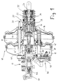
- Fig. 1 is an embodiment of an electronically controlled Vacuum brake booster 10 together with a flanged master brake cylinder 11 for a hydraulic Vehicle brake system illustrated at a glance.
- the Brake booster 10 is in the example shown as so-called tandem brake booster, i.e. in its substantially rotationally symmetrical housing 12 are located there are two movable walls 14, 14 'which cover the interior of the Brake booster housing 12 in two working chambers 16, Subdivide 16 'and two vacuum chambers 18, 18'.
- the two Vacuum chambers 18, 18 ' are not always with one here vacuum source shown connected, for example with the intake tract of an internal combustion engine, while the two Working chambers 16, 16 'by a control valve 20 with a Housing 22 either with negative pressure or with at least atmospheric Pressure can be connected.
- the control valve 20 can either be operated by the driver can be operated directly, for example by its foot power via a not shown here, with a force input rod 24 coupled brake pedal introduced into the control valve 20 is, or it can by means of an electromagnetic actuator 26 can be operated independently of the foot power.
- the electromagnetic actuator 26 essentially one hollow cylindrical magnet armature 28, which on its in Fig. 1st right side is rigidly coupled to a sleeve 30 on the in Fig. 1 right end a first annular valve seat 32 is formed, which with an elastic sealing element 34 interacts sealingly.
- a magnetic coil 36 of the electromagnetic actuating unit 26 moves the magnet armature 28 with respect to FIG. 1 more or less far to the left and thereby lifts the first valve seat 32 from the Sealing element 34 from, whereby a controlled supply of atmospheric pressure to the working chamber 16 is made possible.
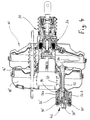
- the sensor arrangement 46 which can be seen better in FIG. 2, has a Housing 48 made of injection molded plastic, on which a first, tubular Air duct 50 and a spaced apart, parallel and also tubular second air duct 52 are integrally formed.
- the material of the two air ducts 50, 52 is selected so that they are both are essentially rigid.
- the first air duct 50 extends from the outside of the brake booster housing 12 located sensor assembly 46 in the brake booster housing 12 into the working chamber 16 '.
- the second Air duct 52 also extends from the sensor arrangement 46 to the inside of the brake booster housing 12, however, the second air duct 52 ends with the the working chamber 16 'interacting vacuum chamber 18'.
- the first Air duct 50 provides in its working chamber side End section existing radial openings 58 and an in Housing 48 arranged connecting tube 60 a fluid connection between the working chamber 16 'and the differential pressure sensor 56 ago.
- the movable wall 14 'through which the First air duct 50 extends is on the outside of the first air duct 50 at 57 (see FIG. 2) sealed and can slide along the first air duct 50.
- the second air duct 52 overlies end opening in the vacuum chamber 18 'and a connecting tube 62 a fluid connection between the vacuum chamber 18 'and the differential pressure sensor 56 in the Sensor arrangement 46 ago.
- the sensor arrangement 46 is therefore one of them able to rest against the movable wall 14 ' Detect differential pressure and from it by means of the not shown control unit, for example as a chip the electronics board 54 may be present, which is currently to calculate effective braking force support.
- the sensor arrangement is shown in the exemplary embodiment shown 46 as a further parameter of each in the primary brake circuit of the master brake cylinder 11 applied hydraulic pressure fed.
- the sensor arrangement 46 has the two air duct 50 and 52 opposite side a socket-like electrical connection 64 in the one Correspondingly plug-type connection of a hydraulic pressure sensor 66 is engaged, which is at the free end of the a leg 68 of the V-shaped housing 70 of the Hydraulic pressure sensor 66 is located.
- the leg 72 of the housing 70 has the hydraulic pressure sensor 66 a connection 74 for the pressure-tight liquid connection the pressure chamber 76 of the primary brake circuit containing hydraulic fluid on.
- the hydraulic fluid in the pressure chamber 76 is at actuated brake booster 10 from the primary piston 40 put under pressure.
- the hydraulic pressure sensor 66 detects that in the pressure chamber 76 prevailing fluid pressure and converts this into a corresponding one electrical signal to the connection 64 of the sensor arrangement 46 is forwarded. In this way the in the small computer contained in the sensor arrangement 46 the amplification power of the brake booster 10 depending on the control the prevailing hydraulic pressure and thus as comfortable perceived response and operating behavior of the entire Ensure brake booster / master cylinder unit.
- the air duct 50, 52 each have a circumferential outside Locking projection 78, 78 'in an area that is at mounted sensor assembly 46 inside the brake booster housing 12 is located.
- the sensor arrangement 46 can be opened this way by simply inserting it into two through openings 80 and 80 'in the wall of the brake booster housing 12 are present, attach to the brake booster 10.
- For pressure-tight sealing of the through openings 80, 80 ' is an annular rubber sleeve 82, 82' in each Through opening 80 or 80 'used through which the associated Air duct 50 or 52 is guided.
- each Gullimi sleeve 82, 82' seals against both Air duct as well as against the wall of the brake booster housing 12 reliably.
- the locking projections 78, 78 ' are designed so that in the direction of insertion the associated rubber sleeve 82, 82 'can be pressed and then lock behind it so that the sensor arrangement 46 without destroying the rubber sleeves 82, 82 ' can be separated from the brake booster housing 12.
- the Sensor arrangement 46 is consequently through the two air ducts 50 and 52 both mechanically and functionally connected to the brake booster 10.
- the first air guide channel 50 not just a fluid connection between the sensor arrangement 46 and the working chamber 16 'ago, but it also serves to accommodate electrical connection lines 84 which from the sensor arrangement 46 or the control device located therein to the electromagnetic actuator 26 of Lead brake booster 10.
- the diameter of the first air duct 50 is chosen so large that the in caused inside by the connecting lines 84 Reduction of the free cross section of the gas exchange through the Air duct 50 is not hindered.
- the master brake cylinder 11 has the V-shaped housing 70 of the hydraulic pressure sensor 66 has the advantage that the hydraulic pressure sensor 66 via its connection 74 before the aforementioned Assembling to be attached to the master cylinder 11 can and that then its electrical connection when assembling of master cylinder 11 and brake booster 10 without further into the socket-like connection 64 of the sensor arrangement 46 clicks into place.
- the V-shaped housing 70 furthermore the advantage that the electrical connection of the Hydraulic pressure sensor 66 on the sensor arrangement 46 itself can solve unintentionally.
- FIGS. 3 and 4 show further exemplary embodiments of the Sensor arrangement 46 reproduced
- Fig. 3 shows a second Embodiment of a sensor arrangement 46 installed in a Tandem vacuum brake booster without electromagnetic Actuation
- Fig. 4 shows a third embodiment of a sensor arrangement 46 installed in a tandem vacuum brake booster with electromagnetic actuation.
- the sensor arrangement 46 shown in FIG. 3 has an im System carrier 92 produced by plastic injection molding, the air duct 50, the one arranged in the latter second air duct 52, in one piece with the system carrier 92 trained support arms 94, and a rear wall 96 of the housing 48 of the sensor arrangement 46 comprises.
- the differential pressure sensor 56 is latched to the support arms 94, which makes it positionally accurate and is securely held in the sensor assembly 46.
- Plug contacts 90 ' which are also attached to the system carrier 92 are electrically in the sensor arrangement 46 with the differential pressure sensor 56 connected and serve to connect the sensor arrangement 46 to an electronic, not shown here Control unit.
- a cap 98 attached to the rear wall 96 is the second part of the housing 48 of the sensor arrangement 46th
- the third exemplary embodiment shown in FIG Sensor arrangement 46 differs from that shown in FIG. 3 second embodiment by a differently trained System carrier 92 '.
- the system carrier 92 ′ comprises a second air duct 52 and a first air duct 50 arranged therein
- Differential pressure sensor is in the third embodiment however, divided into two pressure sensors 56a and 56b, one of which the pressure sensor 56a with the first air duct 50 and the Pressure sensor 56b with the second air duct 52 in a fluid-conducting manner Connection is established.
- the two pressure sensors 56a, 56b Holding arms 94 latched into the system carrier 92 ' are the two pressure sensors 56a, 56b Holding arms 94 latched into the system carrier 92 '.
- FIG. 4 shows the electrical connection line 84 to the electromagnetic Actuating unit 26.
- This connecting line 84 ends in the sensor arrangement 46 in a plug 90 ", which in addition to the two plug contacts 90 'is provided.
Landscapes
- Engineering & Computer Science (AREA)
- Transportation (AREA)
- Mechanical Engineering (AREA)
- Braking Systems And Boosters (AREA)
- Valves And Accessory Devices For Braking Systems (AREA)
- Measuring Fluid Pressure (AREA)
Claims (15)
- Servofrein à dépression (10), comprenant un boítier (12) qui présente au moins une chambre de dépression (18, 18') et une chambre de travail (16, 16') séparée de celle-ci par une paroi mobile (14, 14') qui peut être mise en communication au choix avec une dépression ou avec une pression au moins égale à la pression atmosphérique, et comprenant un dispositif de détection (46) présentant un capteur de différence de pression (56)
caractérisé en ce que
le dispositif de détection (46) présenteet en ce que le boítier (48) du dispositif de détection (46) porte les deux canaux d'air (50, 52) et est fixé au servofrein (10) au moyen des canaux d'air (50, 52).un boítier (48) disposé à l'extérieur du boítier de servofrein (12), dans lequel est disposé le capteur de différence de pression (56),un premier canal d'air (50) relié au capteur de différence de pression (56), dont la longueur suffit pour qu'il s'étende du dispositif de détection (46) jusque dans la chambre de travail (16, 16') du servofrein (10), etun deuxième canal d'air (52) relié au capteur de différence de pression (56) dont la longueur suffit pour qu'il s'étende du dispositif de détection (46) jusque dans la chambre de dépression (18, 18') du servofrein (10), - Servofrein selon la revendication 1,
caractérisé en ce que les deux canaux d'air (50, 52) sont rigides. - Servofrein selon la revendication 1 ou 2,
caractérisé en ce que le premier et / ou le deuxième canal d'air (50, 52) est d'une seule pièce avec le boítier (48). - Servofrein selon l'une quelconque des revendications 1 à 3, caractérisé en ce qu'il y a dans le boítier (48), des bras de maintien (94) pour le capteur de différence de pression (56) qui sont de préférence d'une seule pièce avec le boítier (48) et / ou les canaux d'air (50, 52).
- Servofrein selon l'une quelconque des revendications précédentes,
caractérisé en ce que les deux canaux d'air (50, 52) sont disposés l'un dans l'autre. - Servofrein selon la revendication 5,
caractérisé en ce qu'un canal (50, 52) entoure de façon coaxiale l'autre canal (52, 50). - Servofrein selon l'une quelconque des revendications précédentes,
caractérisé en ce que les canaux d'air (50, 52) peuvent être enclenchés au moyen d'une partie en saillie d'enclenchement (78) de préférence périphérique dans le boítier de servofrein (12). - Servofrein selon l'une quelconque des revendications précédentes,
caractérisé en ce que le premier canal d'air (50) est pourvu dans sa portion d'extrémité située du côté de la chambre de travail d'ouvertures radiales (58) traversant la paroi de canal d'air pour mettre en communication par fluide la chambre de travail (16, 16') avec le premier canal d'air (50). - Servofrein selon l'une quelconque des revendications précédentes,
caractérisé en ce qu'au moins un des deux canaux d'air (50, 52) est dimensionné de telle façon qu'il puisse aussi loger les câbles de raccordement (84) menant du dispositif de détection (46) à une unité d'actionnement (26) électromagnétique du servofrein (10). - Servofrein selon l'une quelconque des revendications précédentes,
caractérisé en ce qu'il y a un raccord (64) sous forme de douille ou de fiche pour un autre capteur, de préférence un capteur de pression (66), en particulier du côté du dispositif de détection (46) faisant face aux canaux d'air (50, 52). - Servofrein selon l'une quelconque des revendications précédentes,
caractérisé en ce qu'une unité de commande électronique est disposée dans le boítier (48). - Servofrein selon l'une quelconque des revendications précédentes,
caractérisé en ce que le dispositif de détection (46) est fixé au servofrein (10) par une ou plusieurs parties en saillies d'enclenchement (78, 78') qui sont formées périphériquement sur la face extérieure du canal d'air (52) ou des canaux d'air (50, 52) et qui sont enclenchées de façon à réaliser une étanchéité dans le boítier de servofrein (12) derrière des manchons en caoutchouc (82, 82') qui sont montés dans des ouvertures de passage (80, 80') dans la paroi du boítier du servofrein pour les canaux d'air (50, 52). - Servofrein selon l'une quelconque des revendications précédentes,
caractérisé en ce que la portion d'extrémité disposée dans la chambre de travail (16, 16') du premier canal d'air (50) présente des ouvertures (58) traversant la paroi de canal d'air qui établissent une communication par fluide entre la chambre de travail (16, 16') et le premier canal d'air (50), et en ce que le premier canal d'air (50) se poursuit par un soufflet en élastomère (86) dont une extrémité est installée de façon à réaliser une étanchéité à l'extrémité libre du premier canal d'air (50) et son autre extrémité est installée de façon à réaliser une étanchéité dans la paroi opposée, éloignée du dispositif de détection (46) du boítier de servofrein (12). - Servofrein selon l'une quelconque des revendications précédentes en combinaison avec la revendication 10,
caractérisé en ce qu'un capteur de pression (66) comprenant un boítier de capteur (70) plié en forme de V est relié avec le raccord (64) sous forme de douille ou de fiche du dispositif de détection (46) pour un autre capteur, qui présente un raccord correspondant au raccord (64) sous forme de douille ou de fiche du dispositif de détection (46) à l'extrémité libre d'une branche (68) du boítier de capteur (70) en forme de V et un raccord (74) pour la communication par fluide avec un maítre cylindre de frein (11) à l'extrémité libre de l'autre branche (72) du boítier de capteur (70) en forme de V. - Servofrein selon l'une quelconque des revendications précédentes,
caractérisé en ce que le servofrein présente une unité d'actionnement (26) électromagnétique qui permet un actionnement du servofrein indépendant de la force exercée par le pied.
Applications Claiming Priority (3)
| Application Number | Priority Date | Filing Date | Title |
|---|---|---|---|
| DE19729158 | 1997-07-08 | ||
| DE19729158A DE19729158C1 (de) | 1997-07-08 | 1997-07-08 | Bremskraftverstärker-Steuergerät und damit ausgerüsteter Bremskraftverstärker |
| PCT/EP1998/004250 WO1999002385A1 (fr) | 1997-07-08 | 1998-07-08 | Ensemble capteur pour servofrein, et servofrein equipe d'un tel ensemble capteur |
Publications (2)
| Publication Number | Publication Date |
|---|---|
| EP0993400A1 EP0993400A1 (fr) | 2000-04-19 |
| EP0993400B1 true EP0993400B1 (fr) | 2002-01-30 |
Family
ID=7835025
Family Applications (1)
| Application Number | Title | Priority Date | Filing Date |
|---|---|---|---|
| EP98940185A Expired - Lifetime EP0993400B1 (fr) | 1997-07-08 | 1998-07-08 | Ensemble capteur pour servofrein, et servofrein equipe d'un tel ensemble capteur |
Country Status (7)
| Country | Link |
|---|---|
| EP (1) | EP0993400B1 (fr) |
| JP (1) | JP2001509452A (fr) |
| KR (1) | KR20010021547A (fr) |
| BR (1) | BR9810551A (fr) |
| DE (2) | DE19729158C1 (fr) |
| ES (1) | ES2172184T3 (fr) |
| WO (1) | WO1999002385A1 (fr) |
Cited By (1)
| Publication number | Priority date | Publication date | Assignee | Title |
|---|---|---|---|---|
| WO2022231073A1 (fr) * | 2021-04-26 | 2022-11-03 | 주식회사 미래브이씨 | Système de détection de pression de récepteur de freinage à ressort pneumatique de véhicule |
Families Citing this family (14)
| Publication number | Priority date | Publication date | Assignee | Title |
|---|---|---|---|---|
| DE19819424A1 (de) * | 1998-04-30 | 1999-11-04 | Continental Teves Ag & Co Ohg | Leitungsführung in einem Vakuum-Bremskraftverstärker |
| US6957220B2 (en) | 2000-11-07 | 2005-10-18 | Research Investment Networks, Inc. | System, method and article of manufacture for tracking and supporting the distribution of content electronically |
| FR2812258B1 (fr) * | 2000-07-25 | 2002-12-27 | Bosch Gmbh Robert | Servofrein pneumatique et procede de montage |
| FR2813840B1 (fr) * | 2000-09-13 | 2003-04-04 | Bosch Gmbh Robert | Servofrein |
| US7191442B2 (en) | 2000-10-30 | 2007-03-13 | Research Investment Network, Inc. | BCA writer serialization management |
| DE10061152A1 (de) * | 2000-12-08 | 2002-06-27 | Lucas Varity Gmbh | Sensoranordnung für einen Unterdruck-Bremskraftverstärker und damit ausgerüsteter Unterdruck-Bremskraftverstärker |
| DE10061153A1 (de) * | 2000-12-08 | 2002-06-27 | Lucas Varity Gmbh | Sensoranordnung für einen Unterdruck-Bremskraftverstärker und damit ausgerüsteter Unterdruck-Bremskraftverstärker |
| DE50209980D1 (de) * | 2001-06-02 | 2007-05-31 | Continental Teves Ag & Co Ohg | Unterdruckbremskraftverstärker einer fahrzeugbremsanlage |
| DE10218972A1 (de) * | 2001-06-02 | 2003-02-20 | Continental Teves Ag & Co Ohg | Unterdruckbremskraftverstärker einer Fahrzeugbremsanlage und Verfahren zum Betrieb einer Fahrzeugbremsanlage mit einem Unterdruckbremskraftverstärker |
| FR2834265B1 (fr) * | 2001-12-31 | 2004-02-27 | Bosch Gmbh Robert | Ensemble a servomoteur d'assistance pneumatique au freinage et procede de determination d'au moins une grandeur physique variant en fonction d'une action de freinage exercee sur cet ensemble |
| EP1474321B1 (fr) | 2002-02-07 | 2008-08-20 | Continental Teves AG & Co. oHG | Procede pour determiner ou etalonner la courbe caracteristique de reglage d'un servofrein a depression |
| DE102004007659B4 (de) * | 2004-02-17 | 2006-02-23 | Lucas Automotive Gmbh | Bremskrafterzeuger für eine hydraulische Fahrzeugbremsanlage |
| DE102004013191B4 (de) * | 2004-03-17 | 2007-02-22 | Lucas Automotive Gmbh | Hauptbremszylinder mit integrierter Druckerkennungseinrichtung |
| JP5537602B2 (ja) * | 2012-06-07 | 2014-07-02 | 日信工業株式会社 | 車両用負圧センサ付き負圧ブースタ |
Family Cites Families (3)
| Publication number | Priority date | Publication date | Assignee | Title |
|---|---|---|---|---|
| DE8712106U1 (de) * | 1987-08-14 | 1988-12-15 | Lucas Industries P.L.C., Birmingham, West Midlands | Pneumatischer Bremskraftverstärker |
| DE4028290C1 (fr) * | 1990-09-06 | 1992-01-02 | Daimler-Benz Aktiengesellschaft, 7000 Stuttgart, De | |
| DE4436297C2 (de) * | 1994-10-11 | 1998-10-08 | Lucas Ind Plc | Elektronisch gesteuerter Bremskraftverstärker und Verfahren zu dessen Betrieb |
-
1997
- 1997-07-08 DE DE19729158A patent/DE19729158C1/de not_active Expired - Fee Related
-
1998
- 1998-07-08 EP EP98940185A patent/EP0993400B1/fr not_active Expired - Lifetime
- 1998-07-08 WO PCT/EP1998/004250 patent/WO1999002385A1/fr not_active Ceased
- 1998-07-08 KR KR1020007000105A patent/KR20010021547A/ko not_active Withdrawn
- 1998-07-08 BR BR9810551-5A patent/BR9810551A/pt not_active IP Right Cessation
- 1998-07-08 ES ES98940185T patent/ES2172184T3/es not_active Expired - Lifetime
- 1998-07-08 JP JP2000501930A patent/JP2001509452A/ja active Pending
- 1998-07-08 DE DE59802970T patent/DE59802970D1/de not_active Expired - Fee Related
Cited By (1)
| Publication number | Priority date | Publication date | Assignee | Title |
|---|---|---|---|---|
| WO2022231073A1 (fr) * | 2021-04-26 | 2022-11-03 | 주식회사 미래브이씨 | Système de détection de pression de récepteur de freinage à ressort pneumatique de véhicule |
Also Published As
| Publication number | Publication date |
|---|---|
| JP2001509452A (ja) | 2001-07-24 |
| WO1999002385A1 (fr) | 1999-01-21 |
| EP0993400A1 (fr) | 2000-04-19 |
| KR20010021547A (ko) | 2001-03-15 |
| BR9810551A (pt) | 2000-08-15 |
| DE19729158C1 (de) | 1998-10-01 |
| DE59802970D1 (de) | 2002-03-14 |
| ES2172184T3 (es) | 2002-09-16 |
Similar Documents
| Publication | Publication Date | Title |
|---|---|---|
| EP0993400B1 (fr) | Ensemble capteur pour servofrein, et servofrein equipe d'un tel ensemble capteur | |
| DE4410699C2 (de) | Hydraulische Bremsanlage für Kraftfahrzeuge | |
| EP0550742A1 (fr) | Ensemble d'actionnement des freins pour vehicules a moteur. | |
| WO2009129887A1 (fr) | Système de cylindre de frein principal à détection d’actionnement pour une installation de freinage de véhicule automobile et installation de freinage de véhicule automobile | |
| EP1397280B1 (fr) | Servofrein a depression d'un systeme de freinage de vehicule | |
| DE10218972A1 (de) | Unterdruckbremskraftverstärker einer Fahrzeugbremsanlage und Verfahren zum Betrieb einer Fahrzeugbremsanlage mit einem Unterdruckbremskraftverstärker | |
| EP0386179B1 (fr) | Circuit de freinage de vehicule a moteur a systeme anti-blocage | |
| EP1339586B1 (fr) | Dispositif capteur pour un servofrein a depression et servofrein a depression equipe dudit capteur | |
| DE19929658A1 (de) | Vakuumservovorrichtung | |
| EP1339583B1 (fr) | Systeme de capteur pour un servofrein a depression | |
| EP1077852A1 (fr) | Servofrein a depression comportant un systeme de production de signal electrique | |
| EP1268249B1 (fr) | Systeme de freinage automobile avec servofrein pneumatique | |
| EP0750556B1 (fr) | Groupe d'actionnement pour systeme de freinage de vehicule automobile | |
| EP1716031B1 (fr) | Generateur de force de freinage pour systeme de freinage hydraulique pour vehicule | |
| DE102013016912A1 (de) | Aktuator-Baugruppe für eine Kraftfahrzeug-Bremsanlage | |
| DE10126326B4 (de) | Unterdruckservoeinheit | |
| DE4410769C2 (de) | Ventilbaugruppe zum Steuern eines Unterdruck-Bremskraftverstärkers mit einer elektromagnetischen Betätigungseinrichtung | |
| EP1274615B1 (fr) | Servo-frein a depression dote d'un auxiliaire frein de secours mecanique | |
| EP0790910A1 (fr) | Ensemble soupape | |
| DE60302464T2 (de) | Unterdruckbremskraftverstärker | |
| DE19845084A1 (de) | Unterdruck-Bremskraftverstärker | |
| EP1126998A1 (fr) | Servofrein a depression avec assistance de freinage d'urgence non magnetique | |
| WO2001066398A1 (fr) | Servofrein a depression comprenant un systeme ameliore d'aide au freinage d'urgence sans aimant |
Legal Events
| Date | Code | Title | Description |
|---|---|---|---|
| PUAI | Public reference made under article 153(3) epc to a published international application that has entered the european phase |
Free format text: ORIGINAL CODE: 0009012 |
|
| 17P | Request for examination filed |
Effective date: 19991228 |
|
| AK | Designated contracting states |
Kind code of ref document: A1 Designated state(s): DE ES FR GB IT SE |
|
| 17Q | First examination report despatched |
Effective date: 20000811 |
|
| GRAG | Despatch of communication of intention to grant |
Free format text: ORIGINAL CODE: EPIDOS AGRA |
|
| GRAG | Despatch of communication of intention to grant |
Free format text: ORIGINAL CODE: EPIDOS AGRA |
|
| GRAH | Despatch of communication of intention to grant a patent |
Free format text: ORIGINAL CODE: EPIDOS IGRA |
|
| GRAH | Despatch of communication of intention to grant a patent |
Free format text: ORIGINAL CODE: EPIDOS IGRA |
|
| GRAA | (expected) grant |
Free format text: ORIGINAL CODE: 0009210 |
|
| REG | Reference to a national code |
Ref country code: GB Ref legal event code: IF02 |
|
| AK | Designated contracting states |
Kind code of ref document: B1 Designated state(s): DE ES FR GB IT SE |
|
| REF | Corresponds to: |
Ref document number: 59802970 Country of ref document: DE Date of ref document: 20020314 |
|
| GBT | Gb: translation of ep patent filed (gb section 77(6)(a)/1977) |
Effective date: 20020409 |
|
| ET | Fr: translation filed | ||
| REG | Reference to a national code |
Ref country code: ES Ref legal event code: FG2A Ref document number: 2172184 Country of ref document: ES Kind code of ref document: T3 |
|
| PLAV | Examination of admissibility of opposition |
Free format text: ORIGINAL CODE: EPIDOS OPEX |
|
| PLBI | Opposition filed |
Free format text: ORIGINAL CODE: 0009260 |
|
| PLBF | Reply of patent proprietor to notice(s) of opposition |
Free format text: ORIGINAL CODE: EPIDOS OBSO |
|
| PLAV | Examination of admissibility of opposition |
Free format text: ORIGINAL CODE: EPIDOS OPEX |
|
| 26 | Opposition filed |
Opponent name: CONTINENTAL TEVES AG + CO. OHG PATENTABTEILUNG Effective date: 20021030 |
|
| PLBF | Reply of patent proprietor to notice(s) of opposition |
Free format text: ORIGINAL CODE: EPIDOS OBSO |
|
| PLBF | Reply of patent proprietor to notice(s) of opposition |
Free format text: ORIGINAL CODE: EPIDOS OBSO |
|
| PLBP | Opposition withdrawn |
Free format text: ORIGINAL CODE: 0009264 |
|
| PLCK | Communication despatched that opposition was rejected |
Free format text: ORIGINAL CODE: EPIDOSNREJ1 |
|
| PLBN | Opposition rejected |
Free format text: ORIGINAL CODE: 0009273 |
|
| STAA | Information on the status of an ep patent application or granted ep patent |
Free format text: STATUS: OPPOSITION REJECTED |
|
| 27O | Opposition rejected |
Effective date: 20050719 |
|
| REG | Reference to a national code |
Ref country code: GB Ref legal event code: 732E |
|
| PGFP | Annual fee paid to national office [announced via postgrant information from national office to epo] |
Ref country code: GB Payment date: 20060614 Year of fee payment: 9 |
|
| PGFP | Annual fee paid to national office [announced via postgrant information from national office to epo] |
Ref country code: FR Payment date: 20060705 Year of fee payment: 9 |
|
| REG | Reference to a national code |
Ref country code: GB Ref legal event code: 732E |
|
| PGFP | Annual fee paid to national office [announced via postgrant information from national office to epo] |
Ref country code: SE Payment date: 20060706 Year of fee payment: 9 Ref country code: IT Payment date: 20070714 Year of fee payment: 10 |
|
| EUG | Se: european patent has lapsed | ||
| GBPC | Gb: european patent ceased through non-payment of renewal fee |
Effective date: 20070708 |
|
| PG25 | Lapsed in a contracting state [announced via postgrant information from national office to epo] |
Ref country code: SE Free format text: LAPSE BECAUSE OF NON-PAYMENT OF DUE FEES Effective date: 20070709 |
|
| PG25 | Lapsed in a contracting state [announced via postgrant information from national office to epo] |
Ref country code: GB Free format text: LAPSE BECAUSE OF NON-PAYMENT OF DUE FEES Effective date: 20070708 |
|
| REG | Reference to a national code |
Ref country code: FR Ref legal event code: ST Effective date: 20080331 |
|
| PG25 | Lapsed in a contracting state [announced via postgrant information from national office to epo] |
Ref country code: FR Free format text: LAPSE BECAUSE OF NON-PAYMENT OF DUE FEES Effective date: 20070731 |
|
| PGFP | Annual fee paid to national office [announced via postgrant information from national office to epo] |
Ref country code: ES Payment date: 20080708 Year of fee payment: 11 Ref country code: DE Payment date: 20080731 Year of fee payment: 11 |
|
| PG25 | Lapsed in a contracting state [announced via postgrant information from national office to epo] |
Ref country code: IT Free format text: LAPSE BECAUSE OF NON-PAYMENT OF DUE FEES Effective date: 20080708 |
|
| PG25 | Lapsed in a contracting state [announced via postgrant information from national office to epo] |
Ref country code: DE Free format text: LAPSE BECAUSE OF NON-PAYMENT OF DUE FEES Effective date: 20100202 |
|
| REG | Reference to a national code |
Ref country code: ES Ref legal event code: FD2A Effective date: 20090709 |
|
| PG25 | Lapsed in a contracting state [announced via postgrant information from national office to epo] |
Ref country code: ES Free format text: LAPSE BECAUSE OF NON-PAYMENT OF DUE FEES Effective date: 20090709 |