EP0993530B1 - Ensemble bati pour engin de travaux publics et procede de fabrication associe - Google Patents
Ensemble bati pour engin de travaux publics et procede de fabrication associe Download PDFInfo
- Publication number
- EP0993530B1 EP0993530B1 EP98932164A EP98932164A EP0993530B1 EP 0993530 B1 EP0993530 B1 EP 0993530B1 EP 98932164 A EP98932164 A EP 98932164A EP 98932164 A EP98932164 A EP 98932164A EP 0993530 B1 EP0993530 B1 EP 0993530B1
- Authority
- EP
- European Patent Office
- Prior art keywords
- wall portion
- side wall
- plate
- axle
- boss
- Prior art date
- Legal status (The legal status is an assumption and is not a legal conclusion. Google has not performed a legal analysis and makes no representation as to the accuracy of the status listed.)
- Expired - Lifetime
Links
Images





Classifications
-
- B—PERFORMING OPERATIONS; TRANSPORTING
- B62—LAND VEHICLES FOR TRAVELLING OTHERWISE THAN ON RAILS
- B62D—MOTOR VEHICLES; TRAILERS
- B62D21/00—Understructures, i.e. chassis frame on which a vehicle body may be mounted
- B62D21/18—Understructures, i.e. chassis frame on which a vehicle body may be mounted characterised by the vehicle type and not provided for in groups B62D21/02 - B62D21/17
- B62D21/186—Understructures, i.e. chassis frame on which a vehicle body may be mounted characterised by the vehicle type and not provided for in groups B62D21/02 - B62D21/17 for building site vehicles or multi-purpose tractors
-
- E—FIXED CONSTRUCTIONS
- E02—HYDRAULIC ENGINEERING; FOUNDATIONS; SOIL SHIFTING
- E02F—DREDGING; SOIL-SHIFTING
- E02F3/00—Dredgers; Soil-shifting machines
- E02F3/04—Dredgers; Soil-shifting machines mechanically-driven
- E02F3/28—Dredgers; Soil-shifting machines mechanically-driven with digging tools mounted on a dipper- or bucket-arm, i.e. there is either one arm or a pair of arms, e.g. dippers, buckets
- E02F3/283—Dredgers; Soil-shifting machines mechanically-driven with digging tools mounted on a dipper- or bucket-arm, i.e. there is either one arm or a pair of arms, e.g. dippers, buckets with a single arm pivoted directly on the chassis
-
- E—FIXED CONSTRUCTIONS
- E02—HYDRAULIC ENGINEERING; FOUNDATIONS; SOIL SHIFTING
- E02F—DREDGING; SOIL-SHIFTING
- E02F9/00—Component parts of dredgers or soil-shifting machines, not restricted to one of the kinds covered by groups E02F3/00 - E02F7/00
- E02F9/08—Superstructures; Supports for superstructures
- E02F9/0841—Articulated frame, i.e. having at least one pivot point between two travelling gear units
-
- Y—GENERAL TAGGING OF NEW TECHNOLOGICAL DEVELOPMENTS; GENERAL TAGGING OF CROSS-SECTIONAL TECHNOLOGIES SPANNING OVER SEVERAL SECTIONS OF THE IPC; TECHNICAL SUBJECTS COVERED BY FORMER USPC CROSS-REFERENCE ART COLLECTIONS [XRACs] AND DIGESTS
- Y10—TECHNICAL SUBJECTS COVERED BY FORMER USPC
- Y10T—TECHNICAL SUBJECTS COVERED BY FORMER US CLASSIFICATION
- Y10T29/00—Metal working
- Y10T29/49—Method of mechanical manufacture
- Y10T29/49616—Structural member making
-
- Y—GENERAL TAGGING OF NEW TECHNOLOGICAL DEVELOPMENTS; GENERAL TAGGING OF CROSS-SECTIONAL TECHNOLOGIES SPANNING OVER SEVERAL SECTIONS OF THE IPC; TECHNICAL SUBJECTS COVERED BY FORMER USPC CROSS-REFERENCE ART COLLECTIONS [XRACs] AND DIGESTS
- Y10—TECHNICAL SUBJECTS COVERED BY FORMER USPC
- Y10T—TECHNICAL SUBJECTS COVERED BY FORMER US CLASSIFICATION
- Y10T29/00—Metal working
- Y10T29/49—Method of mechanical manufacture
- Y10T29/49616—Structural member making
- Y10T29/49622—Vehicular structural member making
-
- Y—GENERAL TAGGING OF NEW TECHNOLOGICAL DEVELOPMENTS; GENERAL TAGGING OF CROSS-SECTIONAL TECHNOLOGIES SPANNING OVER SEVERAL SECTIONS OF THE IPC; TECHNICAL SUBJECTS COVERED BY FORMER USPC CROSS-REFERENCE ART COLLECTIONS [XRACs] AND DIGESTS
- Y10—TECHNICAL SUBJECTS COVERED BY FORMER USPC
- Y10T—TECHNICAL SUBJECTS COVERED BY FORMER US CLASSIFICATION
- Y10T29/00—Metal working
- Y10T29/49—Method of mechanical manufacture
- Y10T29/49826—Assembling or joining
- Y10T29/49904—Assembling a subassembly, then assembling with a second subassembly
Definitions
- the present invention relates generally to a frame assembly, and more particularly to a frame assembly for a construction machine and an associated method of manufacturing the frame assembly.
- the frame assembly is subject to extremely high loads from several different sources.
- the work implement is generally attached to the frame assembly by a pair of lift arms, each of which are raised and lowered by a pair of lift cylinders that extend between each lift arm and the frame assembly.
- the combined weight of the lift arms, the lift cylinders, and the work implement results in a substantial load being communicated to the frame assembly.
- the construction machine also has a mechanism that allows the work implement to be tilted with respect to the lift arms. Tilting the work implement also inputs a substantial load to the frame assembly.
- digging, lifting, and bulldozing operations also input a substantial load to the frame assembly.
- the large size of the frame assembly structure has several disadvantages. Specifically, the overall size, complexity, and weight of the frame assembly increases its manufacturing cost. Additionally, the operation of the construction machine may be hampered because the large size of the frame assembly (1) reduces the lifting capacity of the construction machine and (2) reduces the operator's ability to see the work implement during its use.
- the present invention is directed to overcoming one or more of the problems set forth above.
- the frame assembly includes a central tower portion having a first side wall portion and a second side wall portion.
- the first side wall portion has a first leg and a first arm each extending therefrom, and the second side wall portion has a second leg and a second arm each extending therefrom.
- the frame assembly also includes a hitch support assembly having an upper plate and a lower plate vertically spaced from each other.
- the hitch support assembly also includes a connecting member interposed between and connected to the upper plate and the lower plate.
- the hitch support assembly is secured to the central tower portion such that a lower end of both the first leg and the second leg are supported on the lower plate.
- the frame assembly further includes an axle mount assembly having a first axle plate, a second axle plate, and a support member extending therebetween, wherein both the first arm and the second arm are secured to the support member.
- a method of manufacturing a frame assembly includes the steps of (a) welding a first side wall portion and a second side wall portion to a back wall portion so as to create a central tower portion, wherein the first side wall portion has a first leg and a first arm each extending therefrom, and the second side wall portion has a second leg and a second arm each extending therefrom, (b) welding an upper plate and a lower plate to a connecting member so as to create a hitch support assembly, wherein (1) the connecting member is interposed between the upper plate and the lower plate, and (2) the upper plate and the lower plate are vertically spaced from each other, (c) welding a first axle plate and a second axle plate to a support member so as to create an axle mount assembly, and (d) welding the central tower portion, the hitch support assembly, and the axle mount assembly together so as to create the frame assembly, wherein step (d) is performed after steps (a), (b), and (c) are performed.
- a method of manufacturing a frame assembly includes the steps of (a) creating a first bore in a first frame part, (b) creating a second bore in a second frame part, (c) inserting a first boss within the first bore so that the first boss is positioned in contact with the first frame part, (d) inserting a second boss within the second bore so that the second boss is positioned in contact with the second frame part, (e) positioning an alignment bar simultaneously within the first boss and the second boss so as to cause (1) the first boss to be positioned at a first alignment position relative to the first frame part, and (2) the second boss to be positioned at a second alignment position relative to the second frame part, (f) welding the first boss to the first frame part while the first boss is positioned at the first alignment position, and (g) welding the second boss to the second frame part while the second boss is positioned at the second alignment position.
- Construction machine 10 which incorporates the features of the present invention therein.
- Construction machine 10 includes a rear portion 11 and a front portion 15.
- Rear portion 11 includes a cab assembly 12, a metal main frame 13, a hitch 27 having a pair of hitch pin apertures defined therein (not shown), an engine (not shown), a rear axle housing (not shown) and drive train components (not shown).
- Cab assembly 12, hitch 27, the engine, the rear axle housing, and the drive train components are all mounted to main frame 13.
- Front portion 15 includes a metal frame assembly 16, a front axle housing 17, a work implement 18, a boom 20, a tilt cylinder 22, and a lift cylinder (not shown).
- frame assembly 16 includes a central tower portion 24, a hitch support assembly 26, an axle mount assembly 28, side wall portions 30 and 32, and spacing plates 38 and 40.
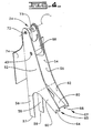
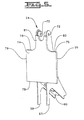
- Central tower portion 24 includes side wall portions 52 and 54, a brace 68, a back wall portion 74, and a central plate 80 as shown in FIGS. 4 and 5.
- Side wall portion 52 has a leg 56 and an arm 60 each extending therefrom.
- a lower end 65 of arm 60 has a notch 64 defined therein.
- Side wall portion 54 has a leg 58 and an arm 62 extending each therefrom.
- a lower end 67 of arm 62 has a notch 66 defined therein.
- An upper portion of side wall portion 52 has a tilt pin aperture 72 defined therein.
- Side wall portion 52 also has a boom aperture 43 defined therein.
- An upper portion of side wall portion 54 has a tilt pin aperture 73 defined therein.
- Side wall portion 54 also has a boom aperture (not shown) defined therein which is identical to boom aperture 43.
- Side wall portions 52 and 54 are secured (e.g. by welding) to back wall portion 74 such that side wall portion 52 and side wall portion 54 are horizontally spaced apart from each other so as to define an interior space 55 therebetween.
- side wall portions 52 and 54 are positioned relative to each other such that tilt pin apertures 72 and 73 are linearly aligned as illustrated by line L 1 .
- Central plate 80 is positioned within interior space 55 and secured to side wall portions 52 and 54.
- Brace 68 is also positioned within interior space 55 and secured to side wall portions 52 and 54.
- Brace 68 is positioned within interior space 55 so that center plate 80 and brace 68 are spaced apart.
- Back wall portion 74 includes a neck portion 81 which extends upwardly from an upper end 75 of back wall portion 74 so as to define a pair of shoulders 76 and 83 of back wall portion 74. Neck portion 81 is interposed between shoulders 76 and 83.
- hitch support assembly 26 includes an upper plate 84, a lower plate 86, a connecting member 96, a wall member 98, stops 102, and brackets 104.
- Upper plate 84 has an aperture 92, notches 90, and hitch pin aperture 88 defined therein.
- Lower plate 86 has an aperture 94 and hitch pin aperture 106 (see FIG. 3) defined therein. Stops 102 are attached to upper plate 84.
- Brackets 104 are attached to wall member 98.
- Upper plate 84 and lower plate 86 are connected (e.g. by welding) to connecting member 96 such that upper plate 84 and lower plate 86 are vertically spaced from each other and connecting member 96 is interposed therebetween.
- Wall member 98 is also interposed between and connected to upper plate 84 and lower plate 86. Wall member 98 is spaced apart from connecting member 96 such that a passageway 100 is defined therebetween.
- Upper plate 84 and lower plate 86 are further positioned relative to each other such that hitch pin apertures 88 and 106 are linearly aligned as illustrated by line L 2 in FIG. 3.
- Hitch support assembly 26 is secured to central tower portion 24 (e.g. by welding) such that a lower edge 78 (see FIG. 5) of back wall portion 74 contacts upper plate 84 as shown in FIG. 3. Hitch support assembly 26 is also secured to central tower portion 24 such that a lower end 57 of leg 56 (see FIG. 4) and a lower end 59 of leg 58 (see FIG. 4) are both supported on lower plate 86 as shown in FIG. 6. In addition, as shown in FIG. 6, hitch support assembly 26 is secured to central tower portion 24 such that legs 56 and 58 extend through aperture 92.
- axle mount assembly 28 includes axle plates 111 and 112, a support member 108, a pair of tie downs 109 and 110, and a pair of axle pads 114 and 115.
- Axle plate 111 has a plurality of axle housing attachment apertures 113 defined therein.
- Axle plate 112 also has a plurality of axle housing attachment apertures 117 defined therein.
- Each axle pad 114 and 115 also has a plurality of axle housing attachment apertures (not shown) defined therein.
- Axle pad 114 is secured to an underside of axle plate 111 such that axle housing attachment apertures 113 align with the axle housing attachment apertures defined in axle pad 114.
- Axle pad 115 is secured to an underside of axle plate 112 such that axle housing attachment apertures 117 align with the axle housing attachment apertures defined in axle pad 115.
- Tie down 109 is secured to an end portion of support member 108. Tie down 109 is also secured to axle plate 111. Tie down 110 is secured to an end portion of support member 108 opposite to the end portion to which tie down 109 is secured. Tie down 110 is secured to axle plate 112. Support member 108 is secured to tie downs 109 and 110 such that support member 108 extends between axle plates 111 and 112. It should be understood that tie downs 109 and 110 increase the structural strength of axle mount assembly 28.
- axle mount assembly 28 is secured to central tower portion 24 such that support member 108 is positioned within notch 64 of arm 60 (see FIG. 4) and notch 66 of arm 62 (see FIG. 4).
- side wall portion 30 has a boom aperture 42 defined therein.
- Side wall portion 30 is secured to an edge 79 of back wall portion 74 so that side wall portion 30 is horizontally spaced from side wall portion 54. Having side wall portion 30 horizontally spaced from side wall portion 54 defines an exterior space 33 therebetween.
- Side wall portion 30 is also secured to edge 79 (see FIG. 5) so that side wall portion 30 is supported on axle plate 112.
- Side wall portion 32 also has a boom aperture 44 defined therein.
- Side wall portion 32 is secured to an edge 77 (see FIG. 5) of back wall portion 74 so that side wall portion 32 is horizontally spaced from side wall portion 52. Having side wall portion 32 horizontally spaced from side wall portion 52 defines an exterior space 35 therebetween.
- Side wall portion 32 is secured to edge 77 so that side wall portion 32 is supported on axle plate 111.
- Side wall portions 30 and 32 are further positioned relative to side wall portions 52 and 54 such that boom apertures 42, 43, 44 and the boom aperture (not shown) defined in side wall portion 54 are linearly aligned as illustrated by line L 3 in FIG. 2.
- Spacing plate 38 is positioned within exterior space 33 and secured to side wall portions 30 and 54. Spacing plate 38 is further positioned within exterior space 33 such that an end thereof contacts support member 108 and an end opposite to the end contacting support member 108 is located below notch 90 (see FIG. 6) defined in hitch support assembly 26.
- Spacing plate 40 is positioned within exterior space 35 and secured to side wall portions 32 and 52. Spacing plate 40 is further positioned within exterior space 35 such that an end thereof contacts support member 108 and an end opposite to the end contacting support member 108 is located below notch 90 (see FIG. 6) defined in hitch support assembly 26. Spacing plates 38 and 40 increase the structural strength of frame assembly 16 and help prevent dirt and rocks from becoming trapped within exterior spaces 33 and 35. It should be understood that spacing plates 38 and 40 and central plate 80 can each have a hole defined therein to allow access to, for example, hydraulic hoses (not shown) that service front portion 15 of construction machine 10 (see FIG. 1).
- Gussets are secured to frame assembly 16 at various places to increase its structural strength. Specifically a gusset 46 is secured to side wall portion 32 and axle plate 111. A gusset (not shown) is also secured to side wall portion 30 and axle plate 112. In addition, a pair of gussets 50 are secured to back wall portion 74 and upper plate 84 of hitch support assembly 26 as shown in FIG. 3.
- frame assembly 16 is manufactured by first creating central tower portion 24, hitch support assembly 26, and axle mount assembly 28 , and then securing (e.g. by welding) central tower portion 24, hitch support assembly 26, axle mount assembly 28, side wall portions 30 and 32, spacing plates 30 and 40, and central plate 80 together to create frame assembly 16.
- axle housing attachment apertures 113 and 117 align with apertures (not shown) defined in front axle housing 17.
- the frame assembly 16 is further positioned relative to front axle housing 17 such that a portion thereof extends into aperture 94 of hitch support assembly 26 (see FIG. 6).
- Bolts (not shown) are then inserted through axle housing attachment apertures 113 and 117, and the apertures defined in front axle housing 17 thereby mounting frame assembly 16 to front axle housing 17.
- a bifurcated end (not shown) of boom 20 is pinned to central tower portion 24 (see FIG. 2) utilizing boom apertures 42, 43, 44 and the boom aperture (not shown) defined in side wall portion 54.
- An end of boom 20, opposite to the bifurcated end, is secured to work implement 18.
- one end of tilt cylinder 22 is pinned to central tower portion 24 utilizing tilt pin apertures 72 and 73 (see FIG. 4).
- An end of tilt cylinder 22 opposite to the one secured to frame assembly 16 is mechanically attached to work implement 18.
- Boom 20, tilt cylinder 22, and the lift cylinder (not shown) cooperate to allow an operator (not shown) positioned within cab assembly 12 to actuate work implement 18.
- Front portion 15 is secured to rear portion 11 by aligning hitch pin apertures 88 and 106 (see FIG. 3) with the hitch pin apertures (not shown) defined in hitch 27 (see FIG. 1) and pinning hitch support assembly 26 to hitch 27. Hydraulic hoses (not shown) are extended through passageway 100 (see FIG. 7) to service front portion 15. A steering cylinder (not shown) is then secured to brackets 104 (see FIG. 7) and main frame 13. Attaching rear portion 11 and front portion 15 in the above described manner allows construction machine 10 to be steered by rotating front portion 15 relative to rear portion 11 in the directions indicated by arrows 174 and 176 as shown in FIG. 1.
- any linearly aligned apertures i.e. hitch pin apertures 88 and 106 (see FIG. 3), tilt pin apertures 72 and 73 (see FIG. 4), and boom apertures 42, 43, and 44 (see FIG. 2)
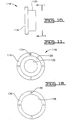
- top hat boss 116 includes a flange 118 and a cylinder portion 120 extending from flange 118. Cylinder portion 120 defines a passageway 122 which extends through top hat boss 116.
- Top hat boss 116 also includes a number of bolt holes 124 defined in flange 118.
- Boss 126 has a passageway 128 and a number of bolt holes 130 defined therein.
- Bolt holes 124 and 130 allow a frame part to be attached to top hat boss 116 or boss 126 if necessary. However, it should be understood that if no frame part is attached to top hat boss 116 or boss 126, then top hat boss 116 and boss 126 do not have to have bolt holes defined therein.
- a laser is used to cut a bore 134 through a frame part 132.
- Top hat boss 116 is then positioned relative to frame part 132 such that cylinder portion 120 extends through bore 134 and flange 118 contacts frame part 132.
- Another bore 144 is laser cut through a frame part 142.
- a top hat boss 146 substantially identical to top hat boss 116, is then positioned relative to frame part 142 such that cylinder portion 150 extends through bore 144 and flange 148 contacts frame part 142.
- bores 134 and 144 are cut large enough such that cylinder portions 120 and 150 do not contact frame parts 132 and 142, respectively. Have bores 134 and 144 cut in such a manner allows top hat bosses 116 and 146 to move relative to frame parts 132 and 142 while positioned bores 134 and 144, respectively, and thus facilitates their alignment.
- top hat boss 116 is positioned in bore 134
- boss 126 is positioned relative to top hat boss 116 such that cylinder portion 120 extends into passageway 128 of boss 126.
- boss 154 is positioned relative to top hat boss 146 such that cylinder portion 150 of top hat boss 146 extends into passageway 153 of boss 154.
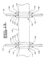
- An expandable alignment bar 140 is then simultaneously positioned within passageway 122 of top hat boss 116 and passageway 152 of top hat boss 146 as shown in FIG. 13. Alignment bar 140 is also simultaneously positioned within passageway 128 of boss 126 and passageway 153 of boss 154. Positioning alignment bar 140 within passageways 122, 152, 128, and 153 (1) locates top hat boss 116 and boss 126 at a first alignment position relative to frame part 132, and (2) locate top hat boss 146 and boss 154 at a second alignment position relative to frame part 142. Top hat boss 116 and boss 126 are then welded to frame part 132 at weld points 138. Top hat boss 146 and boss 154 are welded to frame part 142 at weld points 156. Thereafter, alignment bar 140 is removed to yield linearly aligned apertures defined by top hat bosses 116 and 146.
- FIG. 14 there is shown an alternative method of utilizing a top hat boss to facilitate creation of linearly aligned apertures in a frame assembly. Specifically, a bore 164 is cut through a frame part 162. Top hat boss 158 is then positioned relative to frame part 162 such that cylinder portion 160 extends into bore 164 and flange 159 contacts frame part 162. A second top hat boss 166 is also positioned relative to frame part 162, in an opposing relationship to top hat boss 158, such that cylinder portion 168 extends into bore 164 and flange 165 contacts frame part 162.
- a second pair of top hat bosses are positioned in a bore created in a second frame part (not shown) in an identical manner.
- An alignment bar 170 is then positioned within the passageways of top hat bosses 158 and 166 so as to locate top hat bosses 158 and 166 at a first alignment position relative to frame part 162.
- Alignment bar 170 is also positioned within the passageways of the second pair of top hat bosses so as to locate the second pair of top hat bosses at a second alignment position relative to the second frame part.
- Top hat bosses 158 and 166 are then welded to frame part 162 at weld points 172.
- the second pair of top hat bosses are welded to the second frame part in an identical manner. Thereafter, alignment bar 170 is removed to yield linearly aligned apertures defined by top hat bosses 158, 166 and the second pair of top hat bosses.
- the frame assembly 16 set forth above is designed to cooperate with, and mount, a single boom having a bifurcated end. As such, frame assembly 16 is relatively compact as compared to other frame assemblies. The compactness of frame assembly 16 provides an operator positioned in cab assembly 12 with a relatively unobstructed view of work implement 18. The increased visibility of work implement 18 results in an increase in construction machine 10 performance and productivity.
- frame assembly 16 is relatively small and compact, it still possess the structural strength required to accommodate the high loads generated during the use of work implement 18.
- frame assembly 16 can accommodate these high loads is that its structure is designed to efficiently transfer loads from work implement 18 through central tower portion 24 to front axle housing 17 (via axle mount assembly 28) and main frame 13 (via hitch support assembly 26).
- frame assembly 16 is designed so it can be manufactured by first creating the smaller subassemblies (i.e. central tower portion 24, hitch support assembly 26, and axle mount assembly 28) and then securing the subassemblies together to create frame assembly 16. Creating the aforementioned smaller subassemblies first, allows frame assembly 16 to be manufactured utilizing smaller less expensive machining centers. Being able to utilize smaller less expensive machining centers decreases the manufacturing cost of frame assembly 16.
- an alternative method to reduce manufacturing costs of frame assembly 16 even further is to laser cut or plasma cut bores in the plate components (e.g. side wall portions 52 and 54, upper plate 84 and lower plate 86) of frame assembly 16 prior to being welded together to form the aforementioned subassemblies and then utilize top hat bosses 116, 146 and alignment bar 140 to create linearly aligned apertures as discussed previously.
- top hat bosses 116, 146, 158 and 166 are described above as being utilized to create linearly aligned bores in a frame assembly, these top hat bosses can also be utilized to created linearly aligned bores in all types and sizes of fabricated structures.
Landscapes
- Engineering & Computer Science (AREA)
- Structural Engineering (AREA)
- Mining & Mineral Resources (AREA)
- Civil Engineering (AREA)
- General Engineering & Computer Science (AREA)
- Mechanical Engineering (AREA)
- Architecture (AREA)
- Chemical & Material Sciences (AREA)
- Combustion & Propulsion (AREA)
- Transportation (AREA)
- Body Structure For Vehicles (AREA)
- Shovels (AREA)
Claims (20)
- Structure de châssis (16), comprenant :une partie de tour centrale (24) ayant une première partie de paroi latérale (52) et une deuxième partie de paroi latérale (54), dans laquelle la première partie de paroi latérale (52) comprend une première patte (56) et un premier bras (60) qui s'en étendent, et la deuxième partie de paroi latérale (54) comprend une seconde patte (58) et un second bras (62) qui s'en étendent ;une structure support de barre d'attelage (26) ayant une plaque supérieure (84) et une plaque inférieure (86), verticalement espacées l'une de l'autre, et un élément de liaison (96) interposé entre la plaque supérieure (84) et la plaque inférieure (86) et relié à celles-ci, la structure support de barre d'attelage (26) étant fixée à la partie de tourelle centrale (24) de sorte que les extrémités inférieures (57, 59) de la première patte (56) et de la seconde patte (58) sont portées sur la plaque inférieure (86) ; etune structure de montage d'axe (28) comprenant une première plaque d'axe (111), une seconde plaque d'axe (112) et un élément support (108) s'étendant entre elles, dans lequel le premier bras (60) et le second bras (62) sont fixés à l'élément support (108).
- Structure de châssis (16) selon la revendication 1, dans laquelle :la plaque supérieure (84) de la structure support de barre d'attelage (26) comprend une ouverture (92) ; etla première patte (56) et la seconde patte (58) s'étendent à travers l'ouverture (92).
- Structure de châssis (16) selon la revendication 2, dans laquelle :une première extrémité inférieure (65) du premier bras (60) comprend une première encoche (64) ;une seconde extrémité inférieure (67) du second bras (62) comporte une seconde encoche (66) ; etl'élément support (108) de la structure de montage d'axe (28) est disposé dans la première encoche (64) et la seconde encoche (66).
- Structure de châssis (16) selon la revendication 3, dans laquelle :la première partie de paroi latérale (52) et la deuxième partie de paroi latérale (54) sont espacées horizontalement l'une de l'autre de façon à définir un espace intérieur (55) entre elles.
- Structure de châssis (16) selon la revendication 4, comprenant en outre :une plaque centrale (80) fixée à la première partie de paroi latérale (52) et à la deuxième partie de paroi latérale (54) de sorte que la plaque centrale (80) est disposée dans l'espace intérieur (55).
- Structure de châssis (16) selon la revendication 5, dans lequel la partie de tour centrale (24) comprend en outre :une partie de paroi arrière (74) fixée à la première partie de paroi latérale (52) et à la deuxième partie de paroi latérale (54).
- Structure de châssis (16) selon la revendication 6, dans laquelle :la partie de paroi arrière (74) comprend une partie de col (81) qui s'étend vers le haut à partir d'une extrémité supérieure (75) de la partie de paroi arrière (74) de façon à définir un premier épaulement (76) et un second épaulement (83) ; etla partie de col (81) est interposée entre le premier épaulement (76) et le second épaulement (83).
- Structure de châssis (16) selon la revendication 7, comprenant en outre :une troisième partie de paroi latérale (32) fixée à la partie de paroi arrière (74) de sorte que la troisième partie de paroi latérale (32) et la première partie de paroi latérale (52) sont espacées horizontalement l'une de l'autre de façon à définir un premier espace intérieur (35) entre elles ;une quatrième partie de paroi latérale (30) fixée à la partie de paroi arrière (74) de sorte que la quatrième partie de paroi latérale (30) et la deuxième partie de paroi latérale (54) sont espacées horizontalement l'une de l'autre de façon à définir un second espace extérieur (33) entre elles ;une première plaque d'écartement (40) fixée à la troisième partie de paroi latérale (32) et à la première partie de paroi latérale (52) de sorte que la première plaque d'écartement (40) est disposée dans le premier espace extérieur (35) ; etune second plaque d'écartement (38) fixée à la quatrième partie de paroi latérale (30) et à la deuxième partie de paroi latérale (54) de sorte que la seconde plaque d'écartement (38) est disposée dans le second espace extérieur (33).
- Structure de châssis (16) selon la revendication 8, comprenant en outre :un premier renfort d'axe (114) fixé à la face inférieure de la première d'axe (111), etun second renfort d'axe (115) fixé à la partie inférieure de la seconde plaque d'axe (112).
- Structure de châssis (16) selon la revendication 9, comprenant en outre :une entretoise (68) fixée à la première partie de paroi latérale (52) et à la deuxième partie de paroi latérale (54) de sorte que l'entretoise (68) est (1) disposée dans l'espace intérieur (55) et (2) espacée de la plaque centrale (80).
- Structure de châssis (16) selon la revendication 1, dans laquelle :une partie supérieure de la première partie de paroi latérale (52) comprend une première ouverture d'axe d'inclinaison (72) ;une partie supérieure de la deuxième partie de paroi latérale (54) comprend une seconde ouverture d'axe d'inclinaison (73), etla première ouverture d'axe d'inclinaison (72) est dans l'alignement de la seconde ouverture d'axe d'inclinaison (73).
- Structure de châssis (16) selon la revendication 11, dans laquelle :la plaque supérieure (84) comprend une première ouverture de barre d'attelage (88) ;la plaque inférieure (86) comprend une seconde ouverture de barre d'attelage (106) ; etla première ouverture de barre d'attelage (88) est en alignement avec la seconde ouverture de barre d'attelage (106).
- Structure de châssis (16) selon la revendication 12, dans laquelle :la première plaque d'axe (111) comprend une pluralité de premières ouvertures de fixation de logement d'axe (113), etla seconde plaque d'axe (112) comprend une pluralité de secondes ouvertures de fixation de logement d'axe (117).
- Procédé de fabrication d'une structure de châssis (16) comprenant les étapes suivantes :(a) souder une première partie de paroi latérale (52) et une deuxième partie de paroi latérale (54) à une partie de paroi arrière (74) de façon à créer une partie de tour centrale (24) dans laquelle la première partie de paroi latérale (52) comprend une première patte (56) et un premier bras (60) qui s'en étendent, et la deuxième partie de paroi latérale (54) comprend une seconde patte (58) et un second bras (62) qui s'en étendent :(b) souder une plaque supérieure (84) et une plaque inférieure (86) à un élément de liaison (96) de façon à créer une structure support de barre d'attelage (26) dans lequel (1) l'élément de liaison (96) est interposé entre la plaque supérieure (84) et la plaque inférieure (86) et (2) la plaque supérieure (84) et la plaque inférieure (86) sont espacées verticalement l'une de l'autre ;(c) souder une première plaque d'axe (111) et une seconde plaque d'axe (112) à un élément support (108) de façon à créer une structure de montage d'axe (28) ; et(d) souder la partie de tour centrale (24), la structure support de barre d'attelage (26) et la structure de montage d'axe (28) les unes aux autres de façon à créer la structure de châssis (16), l'étape (d) étant réalisée après les étapes (a), (b), (c).
- Procédé selon la revendication 14, comprenant en outre les étapes suivantes :e) souder une troisième partie de paroi latérale (32) à la partie de paroi arrière (74) de sorte que la troisième partie de paroi latérale (32) et la première partie de paroi latérale (52) sont espacées horizontalement l'une de l'autre de façon à déterminer un premier espace extérieur (35) entre elles ; etf) souder une quatrième partie de paroi latérale (30) fixée à la partie de paroi arrière (74) de sorte que la quatrième partie de paroi latérale (30) et la deuxième partie de paroi latérale (54) sont espacées horizontalement l'une de l'autre de façon à définir entre elles un second espace extérieur (33), dans lequel les étapes (e) et (f) sont réalisées après l'étape (d).
- Procédé selon la revendication 14, dans lequel la partie de la tour centrale (24) est soudée à la structure support de barre d'attelage (26) de sorte que :une extrémité inférieure (57) de la première patte (56) de la première partie de la paroi latérale (52) est portée sur la plaque inférieure (86) de la structure support de barre d'attelage (26), etune extrémité inférieure (59) de la seconde patte (58) de la deuxième partie de la paroi latérale (54) est portée sur la plaque inférieure (86) de la structure support de barre d'attelage (26).
- Procédé selon la revendication 16, dans lequel :la plaque supérieure (84) de la structure support de barre d'attelage (26) comporte une ouverture (92) et ;la première patte (56) et la seconde patte (58) s'étendent à travers l'ouverture (92).
- Procédé selon la revendication 17, dans lequel :une première extrémité inférieure (65) du premier bras (60) comprend une première encoche (64) ;une seconde extrémité inférieure (67) du second bras (62) comporte une seconde encoche (66) ; etl'élément support (108) de la structure de montage d'axe (28) est disposé dans la première encoche (64) et la seconde encoche (66).
- Procédé selon la revendication 14, dans lequel :une partie supérieure de la première partie de paroi latérale (52) comprend une première ouverture d'axe d'inclinaison (72),une partie supérieure de la deuxième partie de paroi latérale (54) comprend une seconde ouverture d'axe d'inclinaison (73),la première ouverture d'axe d'inclinaison (72) est dans l'alignement de la seconde ouverture d'axe d'inclinaison (73),la plaque supérieure (84) comprend une première ouverture de barre d'attelage (88),la plaque inférieure (86) comprend une seconde ouverture de barre d'attelage (106),la première ouverture de barre d'attelage (88) est en alignement avec la seconde ouverture de barre d'attelage (106),la première plaque d'axe (111) comprend une pluralité de premières ouvertures de fixation de logement d'axe (113), etla seconde plaque d'axe (112) comprend une pluralité de secondes ouvertures de fixation de logement d'axe (117).
- Procédé de fabrication d'une structure de châssis (16) comprenant les étapes suivantes :(a) créer un premier alésage (134) dans une première partie de châssis (132) ;(b) créer un second alésage (144) dans une second partie de châssis (142) ;(c) insérer un premier palier (116) dans le premier alésage (134) de sorte que le premier palier (116) soit disposé en contact avec la première partie de châssis (132) ;(d) insérer un second palier (146) dans le second alésage (144) de sorte que le second palier (146) soit en contact avec la seconde partie de châssis (142) ;(e) disposer une barre d'alignement (140) simultanément dans le premier palier (116) et le second palier (146) de façon à amener (1) le premier palier (116) à être positionné dans une position d'alignement par rapport à la première partie de châssis (132), et (2) le second palier (146) à être disposé dans une seconde position d'alignement par rapport à la seconde partie de châssis (142) ;(f) souder le premier palier (116) à la première partie du châssis (132) tandis que le premier palier (116) est positionné à la première position d'alignement ; et(g) souder le second palier (146) à la seconde partie de châssis (142) tandis que le second palier (146) est disposé à la seconde position d'alignement.
Applications Claiming Priority (3)
| Application Number | Priority Date | Filing Date | Title |
|---|---|---|---|
| US5131797P | 1997-06-30 | 1997-06-30 | |
| US51317P | 1997-06-30 | ||
| PCT/EP1998/003672 WO1999001622A1 (fr) | 1997-06-30 | 1998-06-18 | Ensemble bati pour engin de travaux publics et procede de fabrication associe |
Publications (2)
| Publication Number | Publication Date |
|---|---|
| EP0993530A1 EP0993530A1 (fr) | 2000-04-19 |
| EP0993530B1 true EP0993530B1 (fr) | 2002-04-10 |
Family
ID=21970553
Family Applications (1)
| Application Number | Title | Priority Date | Filing Date |
|---|---|---|---|
| EP98932164A Expired - Lifetime EP0993530B1 (fr) | 1997-06-30 | 1998-06-18 | Ensemble bati pour engin de travaux publics et procede de fabrication associe |
Country Status (5)
| Country | Link |
|---|---|
| US (2) | US6062334A (fr) |
| EP (1) | EP0993530B1 (fr) |
| JP (1) | JP2001509557A (fr) |
| DE (1) | DE69804798T2 (fr) |
| WO (1) | WO1999001622A1 (fr) |
Families Citing this family (13)
| Publication number | Priority date | Publication date | Assignee | Title |
|---|---|---|---|---|
| JP2005271602A (ja) * | 2004-03-22 | 2005-10-06 | Komatsu Ltd | 建設機械 |
| JP4422668B2 (ja) * | 2005-10-19 | 2010-02-24 | ヤンマー株式会社 | トラクターローダーバックホーのフレーム構造 |
| USD558649S1 (en) * | 2005-11-19 | 2008-01-01 | Martin Smith | Front cross-member assembly for vehicles |
| CN101446095B (zh) * | 2007-11-30 | 2012-11-07 | 卡特彼勒公司 | 举升缸托架组件及制造方法 |
| US7866700B2 (en) * | 2008-02-11 | 2011-01-11 | Caterpillar Inc | Machine frame |
| CN101983826B (zh) * | 2010-11-12 | 2012-06-20 | 青岛澳柯玛股份有限公司 | 一种冷柜钢板箱壳的焊接方法 |
| US20120145471A1 (en) | 2010-12-14 | 2012-06-14 | Caterpillar, Inc. | Pyramid Structure for Non Engine End Frame (NEEF) of a Wheel Loader |
| US8770908B2 (en) | 2011-03-10 | 2014-07-08 | Caterpillar Inc. | Tilt cylinder support structure |
| US9303383B2 (en) | 2012-07-06 | 2016-04-05 | Caterpillar Inc. | Lift arm cross member |
| JP6028588B2 (ja) * | 2013-01-22 | 2016-11-16 | コベルコ建機株式会社 | 作業機械 |
| US20170107689A1 (en) * | 2015-10-14 | 2017-04-20 | Caterpillar Inc. | Support structure for frame of a machine |
| US10731321B1 (en) | 2020-03-09 | 2020-08-04 | MAC Cormpany, LLC | Compact articulated-steering loader |
| US11932305B2 (en) * | 2022-03-01 | 2024-03-19 | Caterpillar Inc. | Steering bracket for construction machine |
Family Cites Families (21)
| Publication number | Priority date | Publication date | Assignee | Title |
|---|---|---|---|---|
| US3057496A (en) * | 1959-11-19 | 1962-10-09 | Hubert A Garske | Bucket loader |
| US3237790A (en) * | 1963-06-14 | 1966-03-01 | Hough Co Frank | Articulated four-wheel drive earthworking vehicle |
| US3326312A (en) * | 1965-08-04 | 1967-06-20 | Allis Chalmers Mfg Co | Vehicle with auxiliary steerable wheels |
| US3363488A (en) * | 1965-09-23 | 1968-01-16 | Edmund R. Thau | Alignment jig for removing studs from truck hubs |
| US3521719A (en) * | 1966-10-03 | 1970-07-28 | Rhino Ind Inc | Motor vehicle |
| US3521720A (en) * | 1969-02-28 | 1970-07-28 | Isadore R Korotkin | Articulated vehicle with hydraulic drive,steering,and implement manipulating system |
| US3754315A (en) * | 1972-02-24 | 1973-08-28 | Int Harvester Co | Method and means for attaching protection structure to a vehicle frame |
| US4034879A (en) * | 1976-08-16 | 1977-07-12 | Cudmore Eric W | Device for loading and carrying boats on top of vehicles |
| US4081046A (en) * | 1976-10-27 | 1978-03-28 | Massey-Ferguson Inc. | Drive train support for an articulated vehicle |
| US4134507A (en) * | 1977-06-23 | 1979-01-16 | Caterpillar Tractor Co. | Flexing beam assembly |
| US4163498A (en) * | 1977-12-13 | 1979-08-07 | Caterpillar Tractor Co. | Tower assembly |
| US4245714A (en) * | 1978-06-19 | 1981-01-20 | Kersey Frank N | Mining vehicle |
| US4273353A (en) * | 1979-04-05 | 1981-06-16 | John Holmes | Articulator for interconnecting front and rear vehicle chassis portions |
| FR2476250A1 (fr) * | 1980-02-15 | 1981-08-21 | Poclain Sa | Articulation de pivotement |
| US4349307A (en) * | 1981-03-31 | 1982-09-14 | International Harvester Co. | Structure for center hinge and boom cylinder pivot |
| US4768917A (en) * | 1986-10-23 | 1988-09-06 | Vme Americas Inc. | Loader boom mechanism |
| WO1988005845A1 (fr) * | 1987-02-04 | 1988-08-11 | Kabushiki Kaisha Komatsu Seisakusho | Bati avant d'une chargeuse montee sur roues |
| US5125787A (en) * | 1989-11-22 | 1992-06-30 | Ford New Holland, Inc. | Backhoe boom construction |
| DE4341286A1 (de) * | 1993-12-03 | 1995-06-08 | Orenstein & Koppel Ag | Hinterrahmen für knickgelenkte Baumaschinen |
| US5579863A (en) * | 1995-04-10 | 1996-12-03 | Caterpillar Inc. | Steering system for an articulated machine |
| WO1998002619A1 (fr) * | 1996-07-12 | 1998-01-22 | Caterpillar Inc. | Ensemble chassis pour engin de construction articule |
-
1998
- 1998-05-04 US US09/072,151 patent/US6062334A/en not_active Expired - Fee Related
- 1998-06-18 DE DE69804798T patent/DE69804798T2/de not_active Expired - Fee Related
- 1998-06-18 EP EP98932164A patent/EP0993530B1/fr not_active Expired - Lifetime
- 1998-06-18 JP JP2000501313A patent/JP2001509557A/ja active Pending
- 1998-06-18 WO PCT/EP1998/003672 patent/WO1999001622A1/fr not_active Ceased
-
1999
- 1999-11-12 US US09/439,258 patent/US6098870A/en not_active Expired - Fee Related
Also Published As
| Publication number | Publication date |
|---|---|
| US6062334A (en) | 2000-05-16 |
| DE69804798T2 (de) | 2002-11-28 |
| US6098870A (en) | 2000-08-08 |
| DE69804798D1 (de) | 2002-05-16 |
| WO1999001622A1 (fr) | 1999-01-14 |
| JP2001509557A (ja) | 2001-07-24 |
| EP0993530A1 (fr) | 2000-04-19 |
Similar Documents
| Publication | Publication Date | Title |
|---|---|---|
| US6062334A (en) | Frame assembly for a construction machine and an associated method of manufacturing the frame assembly | |
| US7866700B2 (en) | Machine frame | |
| US6860706B2 (en) | Method of verifying coupling of an implement to a work machine | |
| US6106217A (en) | Lift arm arrangement of a construction machine | |
| JPH11293695A (ja) | 作業用具を作業機械に接続するためのリンケ―ジ組立体 | |
| CA1095947A (fr) | Chassis principal de vehicule | |
| US6609587B1 (en) | Frame assembly for a work machine | |
| EP0302942B1 (fr) | Bati avant d'une chargeuse montee sur roues | |
| CA1251039A (fr) | Selle de niveleuse motorisee | |
| JPH11335096A (ja) | 作業機械のリフト組立体 | |
| US3767254A (en) | Tractor body with integral upright a-frame | |
| JPH09209402A (ja) | 旋回式作業車のトラックフレーム | |
| US5988309A (en) | Frame assembly for an articulated construction machine | |
| JP7316463B2 (ja) | ホイール式建設機械 | |
| US6402177B1 (en) | Hitch assembly for the front frame of an articulated construction machine | |
| JP2519829Y2 (ja) | 建設機械のジャッキアップ装置の取付け構造 | |
| JP3562945B2 (ja) | 油圧ショベルの作業機 | |
| JP2003129521A (ja) | 建設機械の旋回フレーム | |
| US5848807A (en) | Frame construction | |
| CN114250813B (zh) | 滑移装载机的工作装置和滑移装载机 | |
| JP3947612B2 (ja) | 作業機装着構造 | |
| US20080003090A1 (en) | Loader support | |
| KR100711135B1 (ko) | 로더 지지대 | |
| JPH0454727Y2 (fr) | ||
| JPH11315550A (ja) | 作業機械のリフトア―ム組立体を製造するための方法 |
Legal Events
| Date | Code | Title | Description |
|---|---|---|---|
| PUAI | Public reference made under article 153(3) epc to a published international application that has entered the european phase |
Free format text: ORIGINAL CODE: 0009012 |
|
| 17P | Request for examination filed |
Effective date: 19991217 |
|
| AK | Designated contracting states |
Kind code of ref document: A1 Designated state(s): DE FR GB IT |
|
| RAP1 | Party data changed (applicant data changed or rights of an application transferred) |
Owner name: CATERPILLAR SARL |
|
| GRAG | Despatch of communication of intention to grant |
Free format text: ORIGINAL CODE: EPIDOS AGRA |
|
| GRAG | Despatch of communication of intention to grant |
Free format text: ORIGINAL CODE: EPIDOS AGRA |
|
| GRAH | Despatch of communication of intention to grant a patent |
Free format text: ORIGINAL CODE: EPIDOS IGRA |
|
| 17Q | First examination report despatched |
Effective date: 20010807 |
|
| REG | Reference to a national code |
Ref country code: GB Ref legal event code: IF02 |
|
| GRAH | Despatch of communication of intention to grant a patent |
Free format text: ORIGINAL CODE: EPIDOS IGRA |
|
| GRAA | (expected) grant |
Free format text: ORIGINAL CODE: 0009210 |
|
| AK | Designated contracting states |
Kind code of ref document: B1 Designated state(s): DE FR GB IT |
|
| PG25 | Lapsed in a contracting state [announced via postgrant information from national office to epo] |
Ref country code: IT Free format text: LAPSE BECAUSE OF FAILURE TO SUBMIT A TRANSLATION OF THE DESCRIPTION OR TO PAY THE FEE WITHIN THE PRESCRIBED TIME-LIMIT;WARNING: LAPSES OF ITALIAN PATENTS WITH EFFECTIVE DATE BEFORE 2007 MAY HAVE OCCURRED AT ANY TIME BEFORE 2007. THE CORRECT EFFECTIVE DATE MAY BE DIFFERENT FROM THE ONE RECORDED. Effective date: 20020410 Ref country code: FR Free format text: LAPSE BECAUSE OF FAILURE TO SUBMIT A TRANSLATION OF THE DESCRIPTION OR TO PAY THE FEE WITHIN THE PRESCRIBED TIME-LIMIT Effective date: 20020410 |
|
| REF | Corresponds to: |
Ref document number: 69804798 Country of ref document: DE Date of ref document: 20020516 |
|
| EN | Fr: translation not filed | ||
| PLBE | No opposition filed within time limit |
Free format text: ORIGINAL CODE: 0009261 |
|
| STAA | Information on the status of an ep patent application or granted ep patent |
Free format text: STATUS: NO OPPOSITION FILED WITHIN TIME LIMIT |
|
| 26N | No opposition filed |
Effective date: 20030113 |
|
| PGFP | Annual fee paid to national office [announced via postgrant information from national office to epo] |
Ref country code: GB Payment date: 20060505 Year of fee payment: 9 |
|
| PGFP | Annual fee paid to national office [announced via postgrant information from national office to epo] |
Ref country code: DE Payment date: 20060630 Year of fee payment: 9 |
|
| GBPC | Gb: european patent ceased through non-payment of renewal fee |
Effective date: 20070618 |
|
| PG25 | Lapsed in a contracting state [announced via postgrant information from national office to epo] |
Ref country code: DE Free format text: LAPSE BECAUSE OF NON-PAYMENT OF DUE FEES Effective date: 20080101 |
|
| PG25 | Lapsed in a contracting state [announced via postgrant information from national office to epo] |
Ref country code: GB Free format text: LAPSE BECAUSE OF NON-PAYMENT OF DUE FEES Effective date: 20070618 |