EP0993564B1 - Actionneur electrique et frein a patins comprenant un tel actionneur - Google Patents
Actionneur electrique et frein a patins comprenant un tel actionneur Download PDFInfo
- Publication number
- EP0993564B1 EP0993564B1 EP98931125A EP98931125A EP0993564B1 EP 0993564 B1 EP0993564 B1 EP 0993564B1 EP 98931125 A EP98931125 A EP 98931125A EP 98931125 A EP98931125 A EP 98931125A EP 0993564 B1 EP0993564 B1 EP 0993564B1
- Authority
- EP
- European Patent Office
- Prior art keywords
- screw
- brake
- bearing
- brake calliper
- actuator
- Prior art date
- Legal status (The legal status is an assumption and is not a legal conclusion. Google has not performed a legal analysis and makes no representation as to the accuracy of the status listed.)
- Expired - Lifetime
Links
- 210000000078 claw Anatomy 0.000 claims description 12
- 238000007789 sealing Methods 0.000 claims description 5
- 238000013016 damping Methods 0.000 claims description 4
- 238000012423 maintenance Methods 0.000 claims description 4
- 230000008878 coupling Effects 0.000 claims description 3
- 238000010168 coupling process Methods 0.000 claims description 3
- 238000005859 coupling reaction Methods 0.000 claims description 3
- 230000000295 complement effect Effects 0.000 claims description 2
- 238000003466 welding Methods 0.000 claims 4
- 238000004026 adhesive bonding Methods 0.000 claims 2
- 238000012544 monitoring process Methods 0.000 claims 2
- 238000005476 soldering Methods 0.000 claims 2
- 238000011068 loading method Methods 0.000 description 7
- 239000011796 hollow space material Substances 0.000 description 4
- 238000006073 displacement reaction Methods 0.000 description 3
- 238000005452 bending Methods 0.000 description 1
- 230000002349 favourable effect Effects 0.000 description 1
- 238000005096 rolling process Methods 0.000 description 1
Images


Classifications
-
- F—MECHANICAL ENGINEERING; LIGHTING; HEATING; WEAPONS; BLASTING
- F16—ENGINEERING ELEMENTS AND UNITS; GENERAL MEASURES FOR PRODUCING AND MAINTAINING EFFECTIVE FUNCTIONING OF MACHINES OR INSTALLATIONS; THERMAL INSULATION IN GENERAL
- F16H—GEARING
- F16H25/00—Gearings comprising primarily only cams, cam-followers and screw-and-nut mechanisms
- F16H25/18—Gearings comprising primarily only cams, cam-followers and screw-and-nut mechanisms for conveying or interconverting oscillating or reciprocating motions
- F16H25/20—Screw mechanisms
- F16H25/22—Screw mechanisms with balls, rollers, or similar members between the co-operating parts; Elements essential to the use of such members
- F16H25/2247—Screw mechanisms with balls, rollers, or similar members between the co-operating parts; Elements essential to the use of such members with rollers
- F16H25/2252—Planetary rollers between nut and screw
-
- F—MECHANICAL ENGINEERING; LIGHTING; HEATING; WEAPONS; BLASTING
- F16—ENGINEERING ELEMENTS AND UNITS; GENERAL MEASURES FOR PRODUCING AND MAINTAINING EFFECTIVE FUNCTIONING OF MACHINES OR INSTALLATIONS; THERMAL INSULATION IN GENERAL
- F16C—SHAFTS; FLEXIBLE SHAFTS; ELEMENTS OR CRANKSHAFT MECHANISMS; ROTARY BODIES OTHER THAN GEARING ELEMENTS; BEARINGS
- F16C19/00—Bearings with rolling contact, for exclusively rotary movement
- F16C19/02—Bearings with rolling contact, for exclusively rotary movement with bearing balls essentially of the same size in one or more circular rows
- F16C19/14—Bearings with rolling contact, for exclusively rotary movement with bearing balls essentially of the same size in one or more circular rows for both radial and axial load
- F16C19/16—Bearings with rolling contact, for exclusively rotary movement with bearing balls essentially of the same size in one or more circular rows for both radial and axial load with a single row of balls
- F16C19/163—Bearings with rolling contact, for exclusively rotary movement with bearing balls essentially of the same size in one or more circular rows for both radial and axial load with a single row of balls with angular contact
- F16C19/166—Four-point-contact ball bearings
-
- F—MECHANICAL ENGINEERING; LIGHTING; HEATING; WEAPONS; BLASTING
- F16—ENGINEERING ELEMENTS AND UNITS; GENERAL MEASURES FOR PRODUCING AND MAINTAINING EFFECTIVE FUNCTIONING OF MACHINES OR INSTALLATIONS; THERMAL INSULATION IN GENERAL
- F16C—SHAFTS; FLEXIBLE SHAFTS; ELEMENTS OR CRANKSHAFT MECHANISMS; ROTARY BODIES OTHER THAN GEARING ELEMENTS; BEARINGS
- F16C33/00—Parts of bearings; Special methods for making bearings or parts thereof
- F16C33/30—Parts of ball or roller bearings
- F16C33/58—Raceways; Race rings
- F16C33/581—Raceways; Race rings integral with other parts, e.g. with housings or machine elements such as shafts or gear wheels
-
- F—MECHANICAL ENGINEERING; LIGHTING; HEATING; WEAPONS; BLASTING
- F16—ENGINEERING ELEMENTS AND UNITS; GENERAL MEASURES FOR PRODUCING AND MAINTAINING EFFECTIVE FUNCTIONING OF MACHINES OR INSTALLATIONS; THERMAL INSULATION IN GENERAL
- F16C—SHAFTS; FLEXIBLE SHAFTS; ELEMENTS OR CRANKSHAFT MECHANISMS; ROTARY BODIES OTHER THAN GEARING ELEMENTS; BEARINGS
- F16C33/00—Parts of bearings; Special methods for making bearings or parts thereof
- F16C33/30—Parts of ball or roller bearings
- F16C33/58—Raceways; Race rings
- F16C33/60—Raceways; Race rings divided or split, e.g. comprising two juxtaposed rings
-
- F—MECHANICAL ENGINEERING; LIGHTING; HEATING; WEAPONS; BLASTING
- F16—ENGINEERING ELEMENTS AND UNITS; GENERAL MEASURES FOR PRODUCING AND MAINTAINING EFFECTIVE FUNCTIONING OF MACHINES OR INSTALLATIONS; THERMAL INSULATION IN GENERAL
- F16D—COUPLINGS FOR TRANSMITTING ROTATION; CLUTCHES; BRAKES
- F16D65/00—Parts or details
- F16D65/14—Actuating mechanisms for brakes; Means for initiating operation at a predetermined position
- F16D65/16—Actuating mechanisms for brakes; Means for initiating operation at a predetermined position arranged in or on the brake
- F16D65/18—Actuating mechanisms for brakes; Means for initiating operation at a predetermined position arranged in or on the brake adapted for drawing members together, e.g. for disc brakes
-
- H—ELECTRICITY
- H02—GENERATION; CONVERSION OR DISTRIBUTION OF ELECTRIC POWER
- H02K—DYNAMO-ELECTRIC MACHINES
- H02K7/00—Arrangements for handling mechanical energy structurally associated with dynamo-electric machines, e.g. structural association with mechanical driving motors or auxiliary dynamo-electric machines
- H02K7/06—Means for converting reciprocating motion into rotary motion or vice versa
-
- F—MECHANICAL ENGINEERING; LIGHTING; HEATING; WEAPONS; BLASTING
- F16—ENGINEERING ELEMENTS AND UNITS; GENERAL MEASURES FOR PRODUCING AND MAINTAINING EFFECTIVE FUNCTIONING OF MACHINES OR INSTALLATIONS; THERMAL INSULATION IN GENERAL
- F16C—SHAFTS; FLEXIBLE SHAFTS; ELEMENTS OR CRANKSHAFT MECHANISMS; ROTARY BODIES OTHER THAN GEARING ELEMENTS; BEARINGS
- F16C2361/00—Apparatus or articles in engineering in general
- F16C2361/45—Brakes
-
- F—MECHANICAL ENGINEERING; LIGHTING; HEATING; WEAPONS; BLASTING
- F16—ENGINEERING ELEMENTS AND UNITS; GENERAL MEASURES FOR PRODUCING AND MAINTAINING EFFECTIVE FUNCTIONING OF MACHINES OR INSTALLATIONS; THERMAL INSULATION IN GENERAL
- F16D—COUPLINGS FOR TRANSMITTING ROTATION; CLUTCHES; BRAKES
- F16D66/00—Arrangements for monitoring working conditions, e.g. wear, temperature
- F16D2066/003—Position, angle or speed
-
- F—MECHANICAL ENGINEERING; LIGHTING; HEATING; WEAPONS; BLASTING
- F16—ENGINEERING ELEMENTS AND UNITS; GENERAL MEASURES FOR PRODUCING AND MAINTAINING EFFECTIVE FUNCTIONING OF MACHINES OR INSTALLATIONS; THERMAL INSULATION IN GENERAL
- F16D—COUPLINGS FOR TRANSMITTING ROTATION; CLUTCHES; BRAKES
- F16D2121/00—Type of actuator operation force
- F16D2121/14—Mechanical
-
- F—MECHANICAL ENGINEERING; LIGHTING; HEATING; WEAPONS; BLASTING
- F16—ENGINEERING ELEMENTS AND UNITS; GENERAL MEASURES FOR PRODUCING AND MAINTAINING EFFECTIVE FUNCTIONING OF MACHINES OR INSTALLATIONS; THERMAL INSULATION IN GENERAL
- F16D—COUPLINGS FOR TRANSMITTING ROTATION; CLUTCHES; BRAKES
- F16D2121/00—Type of actuator operation force
- F16D2121/18—Electric or magnetic
- F16D2121/24—Electric or magnetic using motors
-
- F—MECHANICAL ENGINEERING; LIGHTING; HEATING; WEAPONS; BLASTING
- F16—ENGINEERING ELEMENTS AND UNITS; GENERAL MEASURES FOR PRODUCING AND MAINTAINING EFFECTIVE FUNCTIONING OF MACHINES OR INSTALLATIONS; THERMAL INSULATION IN GENERAL
- F16D—COUPLINGS FOR TRANSMITTING ROTATION; CLUTCHES; BRAKES
- F16D2123/00—Multiple operation forces
-
- F—MECHANICAL ENGINEERING; LIGHTING; HEATING; WEAPONS; BLASTING
- F16—ENGINEERING ELEMENTS AND UNITS; GENERAL MEASURES FOR PRODUCING AND MAINTAINING EFFECTIVE FUNCTIONING OF MACHINES OR INSTALLATIONS; THERMAL INSULATION IN GENERAL
- F16D—COUPLINGS FOR TRANSMITTING ROTATION; CLUTCHES; BRAKES
- F16D2125/00—Components of actuators
- F16D2125/18—Mechanical mechanisms
- F16D2125/20—Mechanical mechanisms converting rotation to linear movement or vice versa
- F16D2125/34—Mechanical mechanisms converting rotation to linear movement or vice versa acting in the direction of the axis of rotation
- F16D2125/40—Screw-and-nut
-
- F—MECHANICAL ENGINEERING; LIGHTING; HEATING; WEAPONS; BLASTING
- F16—ENGINEERING ELEMENTS AND UNITS; GENERAL MEASURES FOR PRODUCING AND MAINTAINING EFFECTIVE FUNCTIONING OF MACHINES OR INSTALLATIONS; THERMAL INSULATION IN GENERAL
- F16D—COUPLINGS FOR TRANSMITTING ROTATION; CLUTCHES; BRAKES
- F16D2125/00—Components of actuators
- F16D2125/18—Mechanical mechanisms
- F16D2125/44—Mechanical mechanisms transmitting rotation
- F16D2125/46—Rotating members in mutual engagement
- F16D2125/50—Rotating members in mutual engagement with parallel non-stationary axes, e.g. planetary gearing
-
- F—MECHANICAL ENGINEERING; LIGHTING; HEATING; WEAPONS; BLASTING
- F16—ENGINEERING ELEMENTS AND UNITS; GENERAL MEASURES FOR PRODUCING AND MAINTAINING EFFECTIVE FUNCTIONING OF MACHINES OR INSTALLATIONS; THERMAL INSULATION IN GENERAL
- F16D—COUPLINGS FOR TRANSMITTING ROTATION; CLUTCHES; BRAKES
- F16D2127/00—Auxiliary mechanisms
- F16D2127/06—Locking mechanisms, e.g. acting on actuators, on release mechanisms or on force transmission mechanisms
-
- F—MECHANICAL ENGINEERING; LIGHTING; HEATING; WEAPONS; BLASTING
- F16—ENGINEERING ELEMENTS AND UNITS; GENERAL MEASURES FOR PRODUCING AND MAINTAINING EFFECTIVE FUNCTIONING OF MACHINES OR INSTALLATIONS; THERMAL INSULATION IN GENERAL
- F16H—GEARING
- F16H25/00—Gearings comprising primarily only cams, cam-followers and screw-and-nut mechanisms
- F16H25/18—Gearings comprising primarily only cams, cam-followers and screw-and-nut mechanisms for conveying or interconverting oscillating or reciprocating motions
- F16H25/20—Screw mechanisms
- F16H2025/2062—Arrangements for driving the actuator
- F16H2025/2075—Coaxial drive motors
-
- F—MECHANICAL ENGINEERING; LIGHTING; HEATING; WEAPONS; BLASTING
- F16—ENGINEERING ELEMENTS AND UNITS; GENERAL MEASURES FOR PRODUCING AND MAINTAINING EFFECTIVE FUNCTIONING OF MACHINES OR INSTALLATIONS; THERMAL INSULATION IN GENERAL
- F16H—GEARING
- F16H25/00—Gearings comprising primarily only cams, cam-followers and screw-and-nut mechanisms
- F16H25/18—Gearings comprising primarily only cams, cam-followers and screw-and-nut mechanisms for conveying or interconverting oscillating or reciprocating motions
- F16H25/20—Screw mechanisms
- F16H2025/2062—Arrangements for driving the actuator
- F16H2025/2087—Arrangements for driving the actuator using planetary gears
-
- F—MECHANICAL ENGINEERING; LIGHTING; HEATING; WEAPONS; BLASTING
- F16—ENGINEERING ELEMENTS AND UNITS; GENERAL MEASURES FOR PRODUCING AND MAINTAINING EFFECTIVE FUNCTIONING OF MACHINES OR INSTALLATIONS; THERMAL INSULATION IN GENERAL
- F16H—GEARING
- F16H25/00—Gearings comprising primarily only cams, cam-followers and screw-and-nut mechanisms
- F16H25/18—Gearings comprising primarily only cams, cam-followers and screw-and-nut mechanisms for conveying or interconverting oscillating or reciprocating motions
- F16H25/20—Screw mechanisms
- F16H25/24—Elements essential to such mechanisms, e.g. screws, nuts
Definitions
- the invention is related to an electric actuator, comprising a screw mechanism and an electric motor which is driveably connected to the screw mechanism which provides a linear movement in response to a rotational movement of the electric motor, said screw mechanism comprising a screw and a nut one of which is supported rotatably with respect to the housing by means of an angular contact ball bearing, said angular contact ball bearing comprising two pairs of contact points the working lines of which intersect each other.
- Such actuator is known from WO-A-9603301.
- the screw member thereof protrudes from a housing, in which housing said screw member is slidably guided by means of a pair of supports.
- said known actuator behaves satisfactorily for providing a rectilinear movement.
- its proper behaviour can only be guaranteed in case said movement and also the loadings are strictly in line with the axis of the screw member.
- the actuator will be blocked and eventually destroyed.
- the object of the invention is to provide an actuator of this kind which provides a better support of the nut, and thereby of the screw member, in relation to the transverse loadings and/or displacements. This object is achieved by the features of the characterising parts of claims 1 and 23.
- the nut is supported particularly well with respect to axial loadings in one direction, i.e. in the direction of forces which exert a load on the pair of contact points having a working line with a smaller contact angle with respect to the axis.
- a limited loading is also possible.
- the stability of the bearing with respect to bending moments is maintained to a large degree, and also with respect to combinations of such moments with respect to axial and radial loadings.
- the outer ring or the inner ring of the angular contact ball bearing is a split outer ring respectively a split inner ring comprising two axial halves, which are pressed against one another under axial forces for providing the desired bearing clearance (positive or negative).
- the axial ring halves may have facing radial abutment faces.
- the axial ring halves may be connected to each other, and may be preloaded in axial direction, by means of a clamping means.
- the nut is rotatably supported and driveably connected to the electric motor
- the screw mechanism may comprise a hollow screw having a central bore opening out at one end of the screw and accommodating an actuating member, which actuating member protrudes from the open end and is connected to the screw at a distance from said open end.
- the actuating member of the actuator according to this embodiment may be connected to an external component, which means that any transverse forces exerted on and/or displacements of such external component will have no direct influence on the screw member.
- said screw member will be exposed mainly to axial loadings, which safeguards its proper functioning.
- the actuating member is accommodated with a radial play within the hollow screw. This radial play may be tuned with respect to the expected transverse displacements.
- the actuator can be connected to the hollow screw in several ways.
- the end of the actuator could be connected to the internal end wall of a bottom which closes the internal hollow space of the screw.
- the actuating member can be connected to the screw by means of a sleeve which fits between said member and screw, which sleeve is at a distance from the open end and which is shorter than said member and the bore.
- the screw may be rotatably supported and driveably connected to the electric motor, and the nut is connected to a brake pad support.
- the screw may be connected to a concentric mounting sleeve, which mounting sleeve at least partly surrounds the screw and which is connected to the inner ring of the angular contact ball bearing, the nut being accommodated at least partly between mounting sleeve and screw.
- the screw mechanism may comprise a roller spindle or a ball spindle.
- the angular contact ball bearing may be either a single row four-point contact ball bearing, or a double row angular contact ball bearing.
- the actuator according to the invention can be applied in various fields.
- said actuator is fit for a brake calliper, comprising a claw piece with two opposite brake pads and an electric actuator according to any of the preceding claims, said actuator comprising an electric motor and a screw mechanism which is driveably connected to the electric motor for providing a linear movement in response to a rotational movement of the electric motor, said screw mechanism comprising a screw and a nut which is supported rotatably with respect to the housing by means of full complement four-point contact ball bearing, said four-point contact ball bearing comprising two pairs of contact points the working lines of which intersect each other.
- Such brake calliper is also known from WO-A-9603301.
- the actuator is mainly loaded in one and the same direction, i.e. in the direction of pressing the brake pads onto the brake disc.
- advantageous use is made of the actuator described before, in that one pair contact points has a working line the angle of which with respect to the axis of the bearing is smaller than the corresponding angle of the other working line.
- the pair of contact points with a working line having an angle with respect to the axis of the bearing less than the corresponding angle of the other working line is loaded by the brake force exerted on the brake pads.
- the outer ring of the four-point contact ball bearing comprises two axial halves, which are pressed against one another under axial forces for providing the desired bearing clearance.
- the working line of the pair of contact points which is loaded by the brake force exerted on the brake pads may have a contact angle with respect to the axis of the bearing less than 45°.
- the screw mechanism may comprise a hollow screw having a central bore opening out at one end of the screw and accommodating an actuating member, which actuating member protrudes from the open end and is connected to the screw within the bore at a distance from said open end, wherein the actuating member cooperates with one of the brake pads and the screw mechanism cooperates with the opposite brake pad.
- the pads thereof have some transverse play within the claw piece, which play manifests itself as soon as said pads are pressed onto the rotating disc to be braked.
- the actuating member of the actuator according to this embodiment is perfectly fit for taking such play, thus preventing the screw mechanism from getting blocked.
- the stator of the electric motor may be connected to the claw piece, and the rotatable part of said motor may be connected to the screw mechanism. Furthermore, the electric motor can be accommodated on a support piece which is rotatably supported in the claw piece, and which is in cooperation with the nut of a roller spindle or a ball spindle.
- the screw mechanism of the brake calliper is a roller spindle or a ball spindle; the nut of the spindle may form an integral part of the inner bearing ring of an axial thrust bearing.
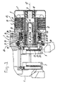
- Figure 1 shows a first embodiment
- Figure 2 shows a second embodiment
- Figure 3 shows a third embodiment.
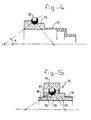
- FIGS 4 and 5 show alternative bearing arrangements for these embodiments.
- the brake calliper shown in figure 1 has a claw piece 1, which in the usual way comprises two brake pads 2, 3. Brake pad 2 is connected to flange 4 of the claw piece 1; by means of support 22, brake pad 3 is connected to an electric actuator, indicated in its entirety with 13.
- the electric actuator 13 comprises an electric motor 5, the stator 6 of which is connected to housing part 7 of the claw piece 1.
- the rotational part 8 of the electric motor 5 is connected to a shaft piece 9, which by means of bearing 10 is rotatably supported in the housing portion 7 of claw piece 1.
- the actuator 4 furthermore comprises a screw mechanism 11, which comprises inter alia a hollow screw 12 and a nut member 33.
- the nut member 33 and the screw member 12 co-operate by means of rolls 14, and constitute a roller spindle, which is known per se.
- the rotational part 8 of the electric motor 5 is driveably connected to the nut member 33, such that upon rotation thereof the screw member 12 is displaced in axial direction via the rolls 14.
- the hollow screw member 12 the hollow space of which is indicated by 15, contains an actuating member 16 which extends from the closed bottom end 17 of the hollow screw member 12, and which protrudes from the open end thereof.
- the actuating member 16 is connected to the screw member 12 near the bottom end 17 thereof, by means of a clamping sleeve 18.
- the actuating member comprises an actuating head 19, which rests against support 22 of brake pad 3.
- This actuating head is sealed with respect to the housing piece 7 of claw piece 1 by means of a bellows 20, which is known per se.
- a support member 22 which by means of pin 21 is rotatably fixed with respect to said actuating head 19.
- the brake pads 2, 3 have some play in a direction transverse with respect to the access of screw member 12.
- said pads will exhibit some transverse movements with respect to the screw member 12.
- the actuating member 16 is not rigidly connected to the screw member 12, the latter one will not be exposed to said transverse movements or loadings. Instead, the actuating member 16 will flex somewhat within the hollow space 15 of hollow screw member 12, which flexing movement is possible due to the radial play which exists between the actuating member 16 and the internal wall of the hollow space 15.
- a four-point contact ball bearing 31 has been applied.
- Said bearing may have a split inner ring or a split outer ring.
- This four-point contact ball bearing 31 comprises one series of rolling balls 32, an inner ring 33 which forms a unity with the nut member of screw mechanism 11, and an outer ring 34 comprising two outer ring halves 35, 36. These outer ring halves 35, 36 together define a raceway 37, 38; the inner ring 33 defines a raceway 39.
- the raceways 37-39 are formed in such a way that four contact points are obtained, comprising two pairs which each define a working line 40, 41.
- the raceways 37-39 have been formed in such a way that the working lines 40-41 intersect the axis of the bearing 31 under mutually different angles.
- Working line 40 intersects the axis 42 under a greater angle than working line 41.
- four-point contact ball bearing 31 according to the invention is in particular fit for taking the axial loads exerted by the brake pads 2, 3 when these are pressed onto the brake disc (not shown).
- the particular orientation of the working lines 40, 41 is obtained by an oblique orientation of the raceways 37-39. This orientation results from the relatively large diameter of the inner surface or land 43 of outer bearing ring half 35, and the smaller inner diameter of the inner surface or land 44 of outer ring half 36.
- the outer surface or land 45 of the inner ring 34 has a diameter which is larger than the outer surface or land 46 thereof.
- the four-point contact ball bearing 31 furthermore comprises a sensor 50, the parts of which are connected to outer ring halve 36 and to inner ring 33.
- This sensor may serve basic functions such as giving information concerning wear compensation, maintenance indication, brake force feedback (ABS), traction control and for vehicle dynamic functions.
- the embodiment shown in figure 2 is to a large extent identical to the embodiment of figure 1. It has a similar brake calliper 1, brake pads 2, 3, support bearing configuration, flange 4, and an electric actuator 13.
- the electric actuator is connected to an electric motor 5, having a rotational part 8 and a stator 6 connected to housing part 7.
- the rotational part 8 is driveably connected to hollow support piece 51, which by means of needle bearing 52 and stub 53 is rotatably supported with respect to the housing 7.
- the support piece 51 has a ring gear wheel 54 with outwardly extending teeth.
- Satellite gear wheels 55 are accommodated on a flange of inner ring 58, and co-operate with a ring gear wheel 56, the outer surface of which is connected to the housing 7. Furthermore, satellite gear wheel 55 co-operates with the ring gear wheel 57.
- the inner ring 58 of bearing 31 co-operates with screw member 59 through the rollers 60, which are contained in cage 61.
- Inner bearing ring 58, screw 59, roller 60 and cage 61 together form a screw spindle known per se, and will not be described in further detail.
- Inner ring 58 and outer ring half 36 furthermore carry rings which together form a sensor for measuring the amount of rotation of the inner ring 58.
- the embodiment of figure 3 is to a large extent identical to the embodiment of figure 1, however the screw mechanism now has a screw 62 which is rotatably supported and connected to the electric motor 5, whereas the nut 63 is non-rotatably supported and connected to the brake support 64.
- the screw is connected to a concentric mounting sleeve 65, which surrounds the screw and is connected to the inner ring 33 of the four-point contact ball bearing 31.
- the nut 60 is accommodated between the mounting sleeve 65 and the screw 62, and co-operates by means of rollers 60 with screw 62.
- the rotatable part 1 of the electric motor 5 co-operates with the mounting sleeve through the satellite gear wheel system comprises ring gear wheel 57.
- Said ring gear wheel engages satellite gear wheels 55 connected to a flange of inner ring 58, which gear wheels 55 in turn engage ring gear 56 connected to the housing 7.
- mounting sleeve 65 is connected to hand brake shaft 71.
- a sealing ring 66 is provided between mounting sleeve 65 and nut 60.
- the mounting sleeve 65 carries a damping ring 68 having external teeth 69, which is part of the satellite gear wheel system described before.
- figure 4 shows a part of the inner ring 72 of a four-point contact bearing, which inner ring forms a unity with support piece 73 which is to be connected with a rotatable part 8 of the electric motor.
- FIG. 5 shows a four-point contact bearing comprising a unitary outer ring 75, and an inner ring 74 having two axial halves 76, 77.
- Axial half 77 has internal screw thread 78, external teeth 79 which are part of the gear wheel system mentioned before, and a connecting groove 80 for connecting a sealing bellows.
- weld 81 By means of weld 81, ring halves 76, 77 are mutually connected.
Landscapes
- Engineering & Computer Science (AREA)
- General Engineering & Computer Science (AREA)
- Mechanical Engineering (AREA)
- Power Engineering (AREA)
- Braking Arrangements (AREA)
- Rolling Contact Bearings (AREA)
- Connection Of Motors, Electrical Generators, Mechanical Devices, And The Like (AREA)
Abstract
Claims (48)
- Dispositif d'actionnement électrique, comportant un boítier qui contient un mécanisme à vis (11) et un moteur électrique (5) qui est relié pour entraínement au mécanisme à vis (11) qui délivre un mouvement linéaire en réponse à un mouvement de rotation du moteur électrique (5), ledit mécanisme à vis (11) comportant une vis (12) et un écrou (33) dont l'un est supporté de façon rotative par rapport au boítier au moyen d'un roulement à billes à contact oblique, ledit roulement à billes à contact oblique (31) comportant deux paires de points de contact dont les lignes de travail (40, 41) s'intersectent, caractérisé en ce qu'une paire de points de contact a une ligne de travail (41) dont l'angle de contact par rapport à l'axe (42) du roulement (31) est plus petit que l'angle de contact correspondant de l'autre ligne de travail opposée (40), et en ce que la bague extérieure (34) ou la bague intérieure du roulement à billes à contact oblique est respectivement une bague extérieure fendue ou une bague intérieure fendue comportant deux moitiés de bague axiales (35, 36), qui sont pressées l'une contre l'autre sous l'effet de forces axiales afin de procurer le jeu de roulement positif ou négatif souhaité.
- Dispositif d'actionnement selon la revendication 1, dans lequel la paire de points de contact ayant la ligne de travail (41) avec l'angle de contact plus petit par rapport à l'axe est orientée afin d'encaisser une force d'actionnement importante.
- Dispositif d'actionnement selon la revendication 1 ou 2, dans lequel les moitiés de bague axiales (35, 36) ont des faces de butée radiales en regard.
- Dispositif d'actionnement selon la revendication 3, dans lequel les moitiés de bague axiales ont des faces extérieures radiales qui sont orientées à l'écart l'une de l'autre, lesdites faces extérieures radiales étant destinées à recevoir des forces de compression axiales afin d'assurer un contact mutuel des faces de butée radiales.
- Dispositif d'actionnement selon la revendication 4, dans lequel les moitiés de bague axiales (35, 36) sont reliées l'une à l'autre, et ont un jeu positif ou négatif défini dans la direction axiale, au moyen d'un serrage, d'un collage, d'un soudage tel que le soudage laser, ou d'un brasage.
- Dispositif d'actionnement selon l'une quelconque des revendications 1 à 5, dans lequel la bague extérieure (34) a deux moitiés de bague axiales (35, 36).
- Dispositif d'actionnement selon l'une quelconque des revendications 1 à 5, dans lequel la bague intérieure a deux moitiés de bague axiales.
- Dispositif d'actionnement selon la revendication 6 ou 7, dans lequel une ou bien les deux moitiés de bague sont pourvues d'un capteur d'encodage destiné à contrôler et commander dans une configuration en boucle fermée avec le moteur, la rétroaction de force de frein, la compensation d'usage, l'indication d'entretien, des fonctions antivol, et caetera.
- Dispositif d'actionnement selon l'une quelconque des revendications 1 à 8, dans lequel l'écrou (13) est supporté de façon rotative et relié pour entraínement au moteur électrique (5), et le mécanisme à vis (11) comporte une vis creuse (12) ayant un alésage central (15) qui s'ouvre à l'extérieur à une extrémité de la vis (12) et reçoit un élément d'actionnement (16), lequel élément d'actionnement (16) dépasse de l'extrémité ouverte et est relié à la vis (12) dans l'alésage (15) à une distance de ladite extrémité ouverte.
- Dispositif d'actionnement selon la revendication 9, dans lequel l'élément d'actionnement (16) est reçu avec un jeu radial dans la vis creuse (12).
- Dispositif d'actionnement selon la revendication 10, dans lequel l'élément d'actionnement (16) est relié à la vis (12) au moyen d'une douille (18) qui s'ajuste entre ledit élément (16) et ladite vis (12), laquelle douille (18) est à une distance de l'extrémité ouverte et est plus courte que ledit élément (16) et ledit alésage (15).
- Dispositif d'actionnement selon l'une quelconque des revendications précédentes, dans lequel l'écrou (33) forme une partie intégrale de la bague de roulement intérieure du roulement à billes à contact oblique (31).
- Dispositif d'actionnement selon l'une quelconque des revendications 1 à 7, dans lequel la vis (62) est supportée de façon rotative et est reliée pour entraínement au moteur électrique (5), et l'écrou (63) est relié à un support de plaquette de frein (64).
- Dispositif d'actionnement selon la revendication 13, dans lequel la vis (62) est reliée à une douille de montage concentrique (65), laquelle douille de montage (65) entoure au moins en partie la vis (62) et est reliée à la bague intérieure du roulement à billes à contact oblique (31), l'écrou (63) étant reçu au moins en partie entre la douille de montage (65) et la vis (62).
- Dispositif d'actionnement selon la revendication 14, dans lequel un élément de bague (66) est fourni entre la douille de montage (65) et l'écrou (63) à des fins d'étanchéité et/ou d'amortissement.
- Dispositif d'actionnement selon la revendication 14 ou 15, dans lequel le moteur électrique (5) engage la douille de montage (65).
- Dispositif d'actionnement selon les revendications 13, 15 ou 16, dans lequel la douille de montage (65) et la vis (62) sont reliées au moyen d'un système de roue dentée à satellite (55 à 57).
- Dispositif d'actionnement selon les revendications 14, 15, 16 ou 17, dans lequel la douille de montage (65) est reliée à un arbre (71) au moyen d'un accouplement sphérique à centrage automatique (67).
- Dispositif d'actionnement selon l'une quelconque des revendications 1 à 18, dans lequel le mécanisme à vis (11) est un axe à rouleau ou un axe à bille avec un écrou rotatif ou avec une vis rotative.
- Dispositif d'actionnement selon l'une quelconque des revendications précédentes, dans lequel un capteur d'encodage est prévu pour détecter et commander le mouvement de rotation du mécanisme à vis (11) dans une configuration fermée avec le moteur, par exemple une rétroaction de force de freinage, une indication d'entretien, un ABS, des fonctions antivol et caetera.
- Dispositif d'actionnement selon l'une quelconque des revendications précédentes, dans lequel le roulement à billes à contact oblique est un roulement à billes à contact complet à quatre points et rangée unique.
- Dispositif d'actionnement selon l'une quelconque des revendications précédentes, dans lequel le moteur électrique (5) a une partie rotative (8) qui est reliée au mécanisme à vis au moyen d'un système de réduction à engrenage, c'est-à-dire un système à engrenage planétaire (55 à 57) combiné avec un système de pignon conique.
- Étrier de frein pour un frein à disque pouvant être actionné électriquement, comportant une pièce de pince (1) avec deux plaquettes de frein opposées (2, 3) et un dispositif d'actionnement électrique (5, 11) selon l'une quelconque des revendications précédentes, ledit dispositif d'actionnement comportant un moteur électrique (5) et un mécanisme à vis (11) qui est relié pour entraínement au moteur électrique (5) afin de délivrer un mouvement linéaire en réponse à un mouvement de rotation du moteur électrique (5), ledit mécanisme à vis (11) comportant une vis (12) et un écrou (33) qui est supporté de façon rotative par rapport au boítier au moyen d'un roulement à billes à contact oblique, ledit roulement à billes à contact oblique (31) comportant deux paires de points de contact dont les lignes de travail (40, 41) s'intersectent, caractérisé en ce qu'une paire de points de contact a une ligne de travail (41) dont l'angle de contact par rapport à l'axe (42) du roulement (31) est plus petit que l'angle correspondant de l'autre ligne de travail (40), en ce que la bague extérieure (34) ou la bague intérieure du roulement à billes à contact oblique est respectivement une bague extérieure fendue ou une bague intérieure fendue comportant deux moitiés de bague axiales (35, 36), qui sont pressées l'une contre l'autre sous l'effet de forces axiales afin de procurer le jeu de roulement positif ou négatif souhaité, et en ce que la paire de points de contact avec une ligne de travail (41) ayant un angle de contact par rapport à l'axe (42) du roulement inférieur à l'angle correspondant de l'autre ligne de travail (40) est chargée par la force de freinage exercée sur les plaquettes de frein (2, 3).
- Etrier de frein selon la revendication 23, dans lequel la bague extérieure (34) du roulement à billes à contact oblique comporte deux moitiés axiales (35, 36), qui sont pressées l'une contre l'autre sous l'effet de forces axiales afin de procurer le jeu de roulement souhaité.
- Etrier de frein selon la revendication 24, dans lequel une ou bien les deux moitiés de bague sont pourvues d'un capteur d'encodage destiné à contrôler et commander dans une configuration en boucle fermée avec le moteur, la rétroaction de force de frein, la compensation d'usage, l'indication d'entretien, des fonctions antivol, et caetera.
- Etrier de frein selon la revendication 24 ou 25, dans lequel les moitiés de bague axiales (35, 36) ont des faces de butée radiales en regard.
- Etrier de frein selon la revendication 26, dans lequel les moitiés de bague axiales ont des faces extérieures radiales qui sont orientées à l'écart l'une de l'autre, lesdites faces extérieures radiales étant destinées à recevoir des forces de compression axiales afin d'assurer un contact mutuel des faces de butée radiales.
- Etrier de frein selon la revendication 27, dans lequel les moitiés de bague axiales (35, 36) sont reliées l'une à l'autre à l'aide de moyens de serrage.
- Etrier de frein selon la revendication 28, dans lequel le jeu de roulement est négatif, nul ou positif.
- Etrier de frein selon la revendication 29, dans lequel la bague extérieure (34) a deux moitiés de bague axiales (35, 36) avec ou sans rebords.
- Etrier de frein selon la revendication 30, dans lequel la bague intérieure a deux moitiés de bague axiales avec ou sans rebords.
- Etrier de frein selon l'une quelconque des revendications 24 à 31, dans lequel l'angle de contact (41) par rapport à l'axe du roulement de la paire de points de contact qui est chargée par la force de freinage exercée sur les plaquettes de frein (2, 3) est entre 45° et 70°.
- Etrier de frein selon l'une quelconque des revendications 23 à 32, dans lequel le stator (6) du moteur électrique (5) est relié à la pièce de pince (1, 7), et la partie rotative (8) dudit moteur est reliée au mécanisme à vis (11).
- Etrier de frein selon l'une quelconque des revendications 23 à 33, dans lequel le mécanisme à vis (11) comporte une vis creuse (12) ayant un alésage central (15) qui s'ouvre à l'extérieur à une extrémité de la vis (12) et reçoit un élément d'actionnement (16), lequel élément d'actionnement (16) dépasse de l'extrémité ouverte et est relié à la vis (12) dans l'alésage (15) à une distance de ladite extrémité ouverte, et dans lequel l'élément d'actionnement (16) coopère avec une des plaquettes de frein (2) et le mécanisme à vis (11) coopère avec la plaquette de frein opposée (2).
- Etrier de frein selon la revendication 34, dans lequel la partie rotative (8) du moteur électrique (5) est logée sur une pièce de support (9) qui est supportée de façon rotative dans la pièce de pince, et qui est en coopération avec l'écrou (13) d'un axe à rouleau ou d'un axe à bille.
- Etrier de frein selon l'une quelconque des revendications 23 à 33, dans lequel la vis (62) est supportée de façon rotative et est reliée pour entraínement au moteur électrique (5), et l'écrou (63) est relié à un support de plaquette de frein (64).
- Etrier de frein selon la revendication 36, dans lequel la vis (62) est reliée à une douille de montage concentrique (65), laquelle douille de montage (65) entoure au moins en partie la vis (62) et est reliée à la bague intérieure (33) du roulement à billes à contact oblique (31), l'écrou (63) étant reçu au moins en partie entre la douille de montage (65) et la vis (62).
- Etrier de frein selon la revendication 37, dans lequel un élément de bague (66) est prévu entre la douille de montage (65) et l'écrou (63) à des fins d'étanchéité et/ou d'amortissement.
- Etrier de frein selon la revendication 37 ou 38, dans lequel le moteur électrique (5) engage la douille de montage (65).
- Etrier de frein selon la revendication 37, 38 ou 39, dans lequel la douille de montage (65) et la vis (62) sont reliées au moyen d'un système de roue dentée à satellite (55 à 57).
- Étrier de frein selon l'une quelconque des revendications 23 à 40, dans lequel la douille de montage (65) est reliée à un arbre (71) au moyen d'un accouplement sphérique à centrage automatique (67).
- Étrier de frein selon l'une quelconque des revendications 23 à 41, dans lequel la partie de dispositif d'actionnement rotative est reliée à un entraínement de frein à main, qui peut par exemple être actionné manuellement ou électriquement.
- Étrier de frein selon l'une quelconque des revendications 23 à 41, dans lequel le moteur électrique (5) a une partie rotative (8) qui est reliée au mécanisme à vis au moyen d'un système de réduction à engrenage, c'est-à-dire un système à engrenage planétaire (55 à 57), ou combinée avec un système de pignon conique.
- Étrier de frein selon l'une quelconque des revendications 23 à 43, dans lequel le mécanisme à vis (11) est un axe à rouleau ou un axe à bille avec un écrou ou une vis rotatif.
- Étrier de frein selon la revendication 44, dans lequel l'écrou (33) de l'axe fait partie intégrante de la bague de roulement intérieure du roulement à billes à contact oblique (31) et/ou du système à engrenage planétaire.
- Etrier de frein selon l'une quelconque des revendications 22 à 45, dans lequel un capteur ou un roulement à capteur est prévu pour détecter le mouvement de rotation du mécanisme à vis (11) dans une configuration en boucle fermée avec le moteur.
- Etrier de frein selon la revendication 24, dans lequel les moitiés de bague sont reliées au moyen d'un serrage, d'un collage, d'un soudage tel que le soudage laser, ou un brasage.
- Etrier de frein selon l'une des revendications 23 à 27, dans lequel au moins un des composants du mécanisme à vis, un roulement et un système de roue dentée est obtenu au moyen d'une opération de tournage dur.
Applications Claiming Priority (3)
| Application Number | Priority Date | Filing Date | Title |
|---|---|---|---|
| NL1006543A NL1006543C2 (nl) | 1997-07-10 | 1997-07-10 | Elektrische actuator en remklauw met een dergelijke actuator. |
| NL1006543 | 1997-07-10 | ||
| PCT/NL1998/000353 WO1999002883A1 (fr) | 1997-07-10 | 1998-06-18 | Actionneur electrique et frein a patins comprenant un tel actionneur |
Publications (2)
| Publication Number | Publication Date |
|---|---|
| EP0993564A1 EP0993564A1 (fr) | 2000-04-19 |
| EP0993564B1 true EP0993564B1 (fr) | 2002-10-30 |
Family
ID=19765320
Family Applications (1)
| Application Number | Title | Priority Date | Filing Date |
|---|---|---|---|
| EP98931125A Expired - Lifetime EP0993564B1 (fr) | 1997-07-10 | 1998-06-18 | Actionneur electrique et frein a patins comprenant un tel actionneur |
Country Status (9)
| Country | Link |
|---|---|
| US (1) | US6325180B1 (fr) |
| EP (1) | EP0993564B1 (fr) |
| JP (1) | JP2001509574A (fr) |
| KR (1) | KR100544081B1 (fr) |
| CN (1) | CN1143064C (fr) |
| AU (1) | AU8132598A (fr) |
| DE (1) | DE69809052T2 (fr) |
| NL (1) | NL1006543C2 (fr) |
| WO (1) | WO1999002883A1 (fr) |
Families Citing this family (41)
| Publication number | Priority date | Publication date | Assignee | Title |
|---|---|---|---|---|
| JP2002510020A (ja) * | 1998-01-20 | 2002-04-02 | エスケイエフ エンジニアリング アンド リサーチ センター ビーブイ | モジュール式アクチュエータおよびアクチュエータを備えるブレーキキャリパ |
| EP1058795B1 (fr) * | 1998-03-05 | 2003-09-24 | Continental Teves AG & Co. oHG | Unite d'actionnement pour frein a disque a actionnement electromecanique |
| NL1009584C2 (nl) * | 1998-07-07 | 2000-01-10 | Skf Eng & Res Centre Bv | Actuator voorzien van een centrale steun, alsmede remklauw met een dergelijke actuator. |
| NL1011731C2 (nl) * | 1999-04-06 | 2000-10-09 | Skf Engineering & Res Services | Actuator met compacte tandwielreductie. |
| NL1013489C2 (nl) * | 1999-11-04 | 2001-05-07 | Skf Eng & Res Centre Bv | Actuator met een hulsvormige steun. |
| US6453761B1 (en) | 2000-11-16 | 2002-09-24 | Thomson Saginaw Ball Screw Company, L.L.C. | Direct attachment electric motor operated ball nut and screw linear actuator |
| KR20030065091A (ko) * | 2002-01-29 | 2003-08-06 | 박정근 | 센서와 전자브레이크를 구비한 자체 신축방식의전기액추에이터 |
| US6991075B2 (en) * | 2002-07-24 | 2006-01-31 | Delphi Technologies, Inc. | Electrically actuated disc brake assembly |
| US7273134B2 (en) * | 2002-07-26 | 2007-09-25 | Continental Teves Ag & Co. Ohg | Actuation unit for an electromechanically-actuated disc brake |
| DE10255764B3 (de) * | 2002-11-28 | 2004-02-26 | Thyssenkrupp Automotive Ag | Fahrzeugfahrwerk |
| ITTO20021103A1 (it) * | 2002-12-20 | 2004-06-21 | Skf Ind Spa | Gruppo attuatore elettromeccanico a vite |
| ITTO20021104A1 (it) * | 2002-12-20 | 2004-06-21 | Skf Ind Spa | Gruppo attuatore elettromeccanico a vite |
| FR2858487B1 (fr) * | 2003-07-29 | 2008-12-26 | Leroy Somer Moteurs | Frein et machine electrique equipee d'un tel frein |
| US7516822B2 (en) * | 2003-08-14 | 2009-04-14 | Arvinmeritor Technology, Llc | Simple electric parking brake actuator motor |
| JP4898123B2 (ja) * | 2005-01-13 | 2012-03-14 | Ntn株式会社 | 電動式直動アクチュエータおよび電動式ブレーキ装置 |
| DE102007021437A1 (de) * | 2007-05-08 | 2008-11-13 | ThyssenKrupp Präzisionsschmiede GmbH | Differential in Leichtbauweise für Kraftfahrzeuge |
| JP5282998B2 (ja) * | 2008-10-07 | 2013-09-04 | Ntn株式会社 | 電動式直動アクチュエータおよび電動式ブレーキ装置 |
| FR2945680B1 (fr) * | 2009-05-15 | 2016-01-22 | Snecma | Actionneur lineaire electromecanique pour turbomachine |
| DE102010038418B4 (de) * | 2010-02-10 | 2011-11-24 | Hanning Elektro-Werke Gmbh & Co. Kg | Elektrische Bremse |
| JP6139077B2 (ja) * | 2012-08-31 | 2017-05-31 | Ntn株式会社 | 電動式直動アクチュエータおよび電動式ディスクブレーキ装置 |
| EP2786845B1 (fr) * | 2013-04-03 | 2016-03-16 | FELCO Motion SA | Outil électroportatif |
| DE102013207618B4 (de) * | 2013-04-26 | 2017-05-18 | Schaeffler Technologies AG & Co. KG | Spindelmutter und zugehöriger Kugelgewindetrieb |
| KR20150015939A (ko) | 2013-08-02 | 2015-02-11 | 주식회사 모아텍 | 스텝 액츄에이터 |
| CN104113160A (zh) * | 2014-07-29 | 2014-10-22 | 北京机械设备研究所 | 一种用于道路拦截系统的电动缸 |
| DE102015206735B3 (de) * | 2015-04-15 | 2016-05-19 | Schaeffler Technologies AG & Co. KG | Aktor mit Planetenwälzgewindetrieb |
| US20170045105A1 (en) * | 2015-08-04 | 2017-02-16 | Persimmon Technologies, Corp. | Electric Brake Caliper |
| FR3041830B1 (fr) * | 2015-09-24 | 2019-04-26 | Aktiebolaget Skf | Verin electromecanique |
| DE102015117252A1 (de) | 2015-10-09 | 2017-04-13 | Knorr-Bremse Systeme für Nutzfahrzeuge GmbH | Elektrische Verschleißnachstellvorrichtung einer Scheibenbremse, eine entsprechende Scheibenbremse und Verfahren zum Lüftspielmessen, -einstellen und Verschleißmessen |
| JP2017116069A (ja) * | 2015-12-25 | 2017-06-29 | セイコーインスツル株式会社 | 軸受装置、情報記録再生装置および軸受装置の製造方法 |
| RU2629481C1 (ru) * | 2016-04-08 | 2017-08-29 | Акционерное общество "Диаконт" | Инвертированный ролико-винтовой редуктор |
| EP3246219A1 (fr) * | 2016-05-19 | 2017-11-22 | Haldex Brake Products Aktiebolag | Unité de transmission de force de freinage, sous-ensemble de frein et groupe d'ensembles de frein |
| JP6838935B2 (ja) * | 2016-10-31 | 2021-03-03 | Ntn株式会社 | 電動アクチュエータ |
| CN107579623B (zh) * | 2017-10-25 | 2019-07-23 | 冶金自动化研究设计院 | 一种低压超低速高精度伺服电机 |
| US11988258B2 (en) * | 2018-05-14 | 2024-05-21 | Sew-Eurodrive Gmbh & Co. Kg | Brake assembly for an electric motor |
| CN110953312A (zh) * | 2018-09-27 | 2020-04-03 | 北京自动化控制设备研究所 | 一种紧凑型串联电动推力矢量伺服作动器 |
| EP3969773B1 (fr) | 2019-05-13 | 2023-04-19 | Brembo S.p.A. | Étrier de frein pour frein à disque |
| EP3969774B1 (fr) * | 2019-05-13 | 2024-02-21 | Brembo S.p.A. | Étrier de frein pour frein à disque |
| FR3097606B1 (fr) * | 2019-06-18 | 2022-07-22 | Skf Motion Tech Ab | Vérin électromécanique à capteur d’effort intégré |
| US11333229B2 (en) * | 2020-03-17 | 2022-05-17 | ZF Active Safety US Inc. | Roller screw system |
| US12338858B2 (en) | 2023-05-02 | 2025-06-24 | Hl Mando Corporation | Brake assembly with asymmetrical shoulder bearing |
| WO2025186880A1 (fr) * | 2024-03-04 | 2025-09-12 | 株式会社ジェイテクト | Arbre rotatif et transmission |
Family Cites Families (21)
| Publication number | Priority date | Publication date | Assignee | Title |
|---|---|---|---|---|
| DE1145446B (de) * | 1958-06-10 | 1963-03-14 | Daimler Benz Ag | Als Freilaufkupplung ausgebildetes Radialkugellager |
| US3370899A (en) * | 1966-06-15 | 1968-02-27 | Phillip R. Eklund | Combination thrust and radial ball bearing |
| US3482892A (en) * | 1967-04-15 | 1969-12-09 | Rothe Erde Eisenwerk | Antifriction bearing |
| GB1357526A (en) * | 1970-06-22 | 1974-06-26 | Skf Uk Ltd | Race rings for rolling bearings and to rolling bearings having such race rings |
| FR2367217A1 (fr) * | 1976-10-07 | 1978-05-05 | Mueller Georg Kugellager | Roulements a billes pour charge radiale, a contact oblique pour charge radiale et a contact oblique pour charge axiale |
| DE2728186A1 (de) | 1977-06-23 | 1979-01-04 | Louis Pohl | Dreipunkt-kugellageranordnung |
| JPS5631524A (en) * | 1979-08-23 | 1981-03-30 | Nippon Seiko Kk | Ball bearing |
| DE3046812A1 (de) * | 1980-12-12 | 1982-07-22 | Audi Nsu Auto Union Ag, 7107 Neckarsulm | Einreihiges radial und axial tragendes kugellager |
| US4804073A (en) | 1980-12-23 | 1989-02-14 | Allied-Signal Inc. | Electrically operated disc brake with back-off protector |
| US4865162A (en) * | 1986-12-15 | 1989-09-12 | Opus Acquisition Corporation | Electrically actuated aircraft brakes |
| NL8701177A (nl) * | 1987-05-15 | 1988-12-01 | Skf Ind Trading & Dev | Werkwijze voor het vervaardigen van een, uit tenminste twee beweegbaar binnen elkaar opgesloten elementen bestaand voorwerp, in het bijzonder een wentellager. |
| US4863293A (en) * | 1988-09-15 | 1989-09-05 | Frost Inc. | Sealed bearing assembly |
| US5251510A (en) * | 1991-09-17 | 1993-10-12 | Dana Corporation | Ring gear fixture and machining process therefor |
| US5333956A (en) * | 1992-10-28 | 1994-08-02 | Hoffman Arnold R | Trolley wheel assembly |
| DE19511287B4 (de) * | 1994-07-21 | 2004-05-06 | Continental Teves Ag & Co. Ohg | Elektromechanische betätigbare Scheibenbremse |
| EP0743470B1 (fr) * | 1995-05-19 | 2000-08-09 | Continental Aktiengesellschaft | Moteur de frein pour frein à actionnement électrique de véhicule |
| JPH0942994A (ja) | 1995-07-28 | 1997-02-14 | Ntn Corp | 旋回角度検出器付き旋回軸受 |
| AU6995196A (en) * | 1995-09-21 | 1997-04-09 | Lucas Industries Public Limited Company | Improvements in electrically-operated disc brake assemblies for vehicles |
| JP3540065B2 (ja) * | 1995-09-29 | 2004-07-07 | Ntn株式会社 | 組合せ転がり軸受 |
| DE19628804B4 (de) * | 1996-07-17 | 2005-09-01 | Continental Teves Ag & Co. Ohg | Elektromechanisch betätigbare Scheibenbremse |
| DE19629936C1 (de) * | 1996-07-24 | 1997-11-20 | Siemens Ag | Bremsanlage für ein Kraftfahrzeug |
-
1997
- 1997-07-10 NL NL1006543A patent/NL1006543C2/nl not_active IP Right Cessation
-
1998
- 1998-06-18 AU AU81325/98A patent/AU8132598A/en not_active Abandoned
- 1998-06-18 EP EP98931125A patent/EP0993564B1/fr not_active Expired - Lifetime
- 1998-06-18 CN CNB988069938A patent/CN1143064C/zh not_active Expired - Fee Related
- 1998-06-18 US US09/446,505 patent/US6325180B1/en not_active Expired - Fee Related
- 1998-06-18 KR KR1020007000144A patent/KR100544081B1/ko not_active Expired - Fee Related
- 1998-06-18 DE DE69809052T patent/DE69809052T2/de not_active Expired - Fee Related
- 1998-06-18 JP JP2000502336A patent/JP2001509574A/ja active Pending
- 1998-06-18 WO PCT/NL1998/000353 patent/WO1999002883A1/fr not_active Ceased
Also Published As
| Publication number | Publication date |
|---|---|
| US6325180B1 (en) | 2001-12-04 |
| WO1999002883A1 (fr) | 1999-01-21 |
| KR20010021586A (ko) | 2001-03-15 |
| CN1143064C (zh) | 2004-03-24 |
| NL1006543C2 (nl) | 1999-01-12 |
| CN1262726A (zh) | 2000-08-09 |
| JP2001509574A (ja) | 2001-07-24 |
| EP0993564A1 (fr) | 2000-04-19 |
| DE69809052D1 (de) | 2002-12-05 |
| KR100544081B1 (ko) | 2006-01-23 |
| AU8132598A (en) | 1999-02-08 |
| DE69809052T2 (de) | 2003-06-12 |
Similar Documents
| Publication | Publication Date | Title |
|---|---|---|
| US6325180B1 (en) | Electric actuator and calliper brake comprising such actuator | |
| US6554109B1 (en) | Actuator having a central support, and brake calliper comprising such actuator | |
| US6666308B1 (en) | Modular actuator, and brake calliper comprising such actuator | |
| US4995755A (en) | Ball joint | |
| US6367592B1 (en) | Modular actuator, and brake caliper comprising such actuator | |
| EP1232347B1 (fr) | Actionneur avec compensation de desalignement | |
| EP1437517A2 (fr) | Palier à double joint d'étanchéité | |
| CN102762395A (zh) | 用于机动车的车轮悬架 | |
| EP0993565B1 (fr) | Actionneur comprenant un mecanisme a vis protegee et frein a patins comprenant un tel actionneur | |
| US4197926A (en) | Brake and steering knuckle apparatus | |
| US6257795B1 (en) | Connection between a tie rod linkage and a steering knuckle arm | |
| EP1121536B1 (fr) | Coussinet de contact angulaire asymetrique | |
| US6984071B2 (en) | Instrumented antifriction bearing for control wheel | |
| US5060750A (en) | Axle shaft retention structure | |
| US12607241B2 (en) | Brake device | |
| KR20040017365A (ko) | 차량 코너 모듈 및 그러한 모듈을 구비한 조립체 | |
| US20220258798A1 (en) | Wheel suspension for a vehicle | |
| JPH0334701Y2 (fr) | ||
| CA2023078C (fr) | Dispositif de retenue pour arbre de roue motrice | |
| GB1572942A (en) | Disc brakes |
Legal Events
| Date | Code | Title | Description |
|---|---|---|---|
| PUAI | Public reference made under article 153(3) epc to a published international application that has entered the european phase |
Free format text: ORIGINAL CODE: 0009012 |
|
| 17P | Request for examination filed |
Effective date: 19991220 |
|
| AK | Designated contracting states |
Kind code of ref document: A1 Designated state(s): DE FR GB IT |
|
| GRAG | Despatch of communication of intention to grant |
Free format text: ORIGINAL CODE: EPIDOS AGRA |
|
| 17Q | First examination report despatched |
Effective date: 20020116 |
|
| GRAG | Despatch of communication of intention to grant |
Free format text: ORIGINAL CODE: EPIDOS AGRA |
|
| GRAH | Despatch of communication of intention to grant a patent |
Free format text: ORIGINAL CODE: EPIDOS IGRA |
|
| GRAH | Despatch of communication of intention to grant a patent |
Free format text: ORIGINAL CODE: EPIDOS IGRA |
|
| GRAA | (expected) grant |
Free format text: ORIGINAL CODE: 0009210 |
|
| AK | Designated contracting states |
Kind code of ref document: B1 Designated state(s): DE FR GB IT |
|
| REG | Reference to a national code |
Ref country code: GB Ref legal event code: FG4D |
|
| REF | Corresponds to: |
Ref document number: 69809052 Country of ref document: DE Date of ref document: 20021205 |
|
| ET | Fr: translation filed | ||
| PLBE | No opposition filed within time limit |
Free format text: ORIGINAL CODE: 0009261 |
|
| STAA | Information on the status of an ep patent application or granted ep patent |
Free format text: STATUS: NO OPPOSITION FILED WITHIN TIME LIMIT |
|
| 26N | No opposition filed |
Effective date: 20030731 |
|
| PGFP | Annual fee paid to national office [announced via postgrant information from national office to epo] |
Ref country code: GB Payment date: 20040528 Year of fee payment: 7 |
|
| PG25 | Lapsed in a contracting state [announced via postgrant information from national office to epo] |
Ref country code: GB Free format text: LAPSE BECAUSE OF NON-PAYMENT OF DUE FEES Effective date: 20050618 |
|
| GBPC | Gb: european patent ceased through non-payment of renewal fee |
Effective date: 20050618 |
|
| PGFP | Annual fee paid to national office [announced via postgrant information from national office to epo] |
Ref country code: FR Payment date: 20060620 Year of fee payment: 9 |
|
| PGFP | Annual fee paid to national office [announced via postgrant information from national office to epo] |
Ref country code: DE Payment date: 20060731 Year of fee payment: 9 |
|
| PGFP | Annual fee paid to national office [announced via postgrant information from national office to epo] |
Ref country code: IT Payment date: 20070626 Year of fee payment: 10 |
|
| REG | Reference to a national code |
Ref country code: FR Ref legal event code: ST Effective date: 20080229 |
|
| PG25 | Lapsed in a contracting state [announced via postgrant information from national office to epo] |
Ref country code: DE Free format text: LAPSE BECAUSE OF NON-PAYMENT OF DUE FEES Effective date: 20080101 |
|
| PG25 | Lapsed in a contracting state [announced via postgrant information from national office to epo] |
Ref country code: FR Free format text: LAPSE BECAUSE OF NON-PAYMENT OF DUE FEES Effective date: 20070702 |
|
| PG25 | Lapsed in a contracting state [announced via postgrant information from national office to epo] |
Ref country code: IT Free format text: LAPSE BECAUSE OF NON-PAYMENT OF DUE FEES Effective date: 20080618 |