EP0993583B1 - Robinet pour appareil a gaz, et procede de calibrage d'un tel robinet - Google Patents
Robinet pour appareil a gaz, et procede de calibrage d'un tel robinet Download PDFInfo
- Publication number
- EP0993583B1 EP0993583B1 EP98935061A EP98935061A EP0993583B1 EP 0993583 B1 EP0993583 B1 EP 0993583B1 EP 98935061 A EP98935061 A EP 98935061A EP 98935061 A EP98935061 A EP 98935061A EP 0993583 B1 EP0993583 B1 EP 0993583B1
- Authority
- EP
- European Patent Office
- Prior art keywords
- rod
- tap
- bore
- orifice
- axial
- Prior art date
- Legal status (The legal status is an assumption and is not a legal conclusion. Google has not performed a legal analysis and makes no representation as to the accuracy of the status listed.)
- Expired - Lifetime
Links
Images

Classifications
-
- F—MECHANICAL ENGINEERING; LIGHTING; HEATING; WEAPONS; BLASTING
- F16—ENGINEERING ELEMENTS AND UNITS; GENERAL MEASURES FOR PRODUCING AND MAINTAINING EFFECTIVE FUNCTIONING OF MACHINES OR INSTALLATIONS; THERMAL INSULATION IN GENERAL
- F16K—VALVES; TAPS; COCKS; ACTUATING-FLOATS; DEVICES FOR VENTING OR AERATING
- F16K5/00—Plug valves; Taps or cocks comprising only cut-off apparatus having at least one of the sealing faces shaped as a more or less complete surface of a solid of revolution, the opening and closing movement being predominantly rotary
- F16K5/08—Details
- F16K5/12—Arrangements for modifying the way in which the rate of flow varies during the actuation of the valve
-
- F—MECHANICAL ENGINEERING; LIGHTING; HEATING; WEAPONS; BLASTING
- F23—COMBUSTION APPARATUS; COMBUSTION PROCESSES
- F23N—REGULATING OR CONTROLLING COMBUSTION
- F23N1/00—Regulating fuel supply
- F23N1/007—Regulating fuel supply using mechanical means
-
- F—MECHANICAL ENGINEERING; LIGHTING; HEATING; WEAPONS; BLASTING
- F23—COMBUSTION APPARATUS; COMBUSTION PROCESSES
- F23N—REGULATING OR CONTROLLING COMBUSTION
- F23N5/00—Systems for controlling combustion
- F23N5/02—Systems for controlling combustion using devices responsive to thermal changes or to thermal expansion of a medium
- F23N5/10—Systems for controlling combustion using devices responsive to thermal changes or to thermal expansion of a medium using thermocouples
- F23N5/107—Systems for controlling combustion using devices responsive to thermal changes or to thermal expansion of a medium using thermocouples using mechanical means, e.g. safety valves
Definitions
- the present invention relates to a tap for gas appliance, and in particular for a space heating appliance catalysis.
- It also relates to a method for calibrating such a tap.
- valves in which a conical plug is adjustable rotating between a zero power position (power cut) and power positions variable.
- the plug is loaded axially to have against the wall of the conical chamber in which it is mounted sufficient support so that the seal is ensured when the plug is in the closed position.
- Tapered surfaces are expensive to make, especially with the required precision.
- the tap does not contain zero power position.
- the shutdown of the appliance is obtained by shutting off the gas supply upstream tap.
- the regulating member can then be a rod cylindrical in which a cavity is formed, which opens radially outwards through holes of passage of different diameters. During the rotation of the rod, these holes come successively in look of an orifice, formed through the wall of body bore. Conventionally, through holes are three in number. So when the bigger hole small diameter is located opposite the orifice of the bore, the device operates at minimum power; when it's the hole of intermediate diameter, respectively of larger diameter, the device operates at medium power, respectively maximum.
- the purpose of the present invention is to provide a gas appliance valve that does not have the disadvantages above stated.
- the tap has first and second angular stops to limit the rotation of the rod inside the bore such that said coincidence area varies continuously and gradually between a value maximum when the rod is against the first stop angular and a nonzero minimum value when the rod is against the second angular stop.
- An advantage of the invention is that it provides a continuous range of device operating powers instead of the only intermediate power value proposed by taps of the prior art. The user can adjust the power of his device between minimum and maximum values.
- the tap also has integrated calibration means comprising means for axially adjusting said position stable axial.
- the rod benefits from a deflection axial inside the bore, and the position is adjusted stable axial of the rod relative to the bore in exploiting said travel.
- This setting varies the area of coincidence between the outlet for the means of communication and the orifice for each angular position of the stem.
- Said calibration performed for an angular position of the rod, has the effect of adjusting in one only once the minimum flow, the maximum flow and the intermediate flows passing through the tap, for different possible angular positions of the rod.
- said means axial adjustment include a thrust bearing fixed to the valve body, in an adjustable position parallel to the axis of the bore.
- the thrust bearing comprises at least a lug for its fixing by screw on the body of the tap.
- the axial adjustment means comprise a deformability of this tab under the screwing action.
- the position predetermined angularity of the rod can be one of two positions in which the rod is in abutment angular or an intermediate position.
- the calibration of tap is then done based on the minimum flow required, on the maximum flow required, or else on a flow predetermined intermediary, respectively.
- the gas used for calibration is not necessarily combustible.
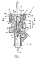
- the tap 2 includes (see for example Figure 1) a body 4 in which a bore 18 (FIG. 3) of axis 20 is formed, and of variable section.
- the bore 18 thus comprises a first portion 22 in which the body 8 of a safety solenoid valve is tightly fitted and fixed, a second portion 24 connected to the portion 22 by a shoulder 23 forming a seat for the valve 10 of the solenoid valve, a third portion 26, and a fourth portion 28.
- the body 4 has a gas inlet path 30, opening through a first orifice 32 in the first portion 22 of the bore 18 between the body 8 of the solenoid valve and the seat 23.
- the path 30 opens to the outside of the body 4 through a second orifice 34, which can be connected, not shown, to a gas source, also not shown, located at upstream of valve 2 in the installation.
- the body 4 has a path 36 for discharging gas, opening into the third portion 26 of the bore 18 through a third orifice 38 and outside the body 4 by a fourth orifice 40, which can be connected, of not shown, to the device, also not shown, that the valve 2 supplies gas, and located in downstream of valve 2 in the installation.
- the body 4 can have an additional path 42, opening into the second portion 24 of the bore 18 through a fifth orifice 44 and outside the body 4 by a sixth orifice 46, which can be connected, of not shown, to a pilot light of the apparatus feed.
- the body 8 contains an electromagnet, the plunger 11 carries the valve 10 returned to its seat 23 by a return spring 12.
- valve 10 When the tap and the appliance supplied by it are at rest ( Figure 1), the valve 10 is held in waterproof support on its seat 23 by the spring 12, thus closing off the passage of gas between the upstream path 30 on the one hand and the two downstream paths 36 and 42 on the other go.
- the gas arriving through path 30 passes freely through the pilot light path 42.
- the gas also passes through the main evacuation route 36 with a flow which is determined by adjusting the positioning of a rod setting 6 of generally cylindrical shape engaged in the second, third and fourth positions 24, 26, 28 of bore 18.
- the diameter of the adjustment rod 6 is determined so that said adjustment rod 6 can slide and rotate snugly and substantially tightly in the third portion 26 of bore 18, where the gas evacuation route 36.
- the outer end 54 of the rod 6 protrudes the bore 18 through one end 50 of the body 4 and at through a window 114 of a thrust bearing 14 fixed to the end 50 of the body 4 by two screws 16.
- the end 54 has means 55 for receiving a button (not shown) or any other gripping device allowing the user to insert said rod setting 6 or rotate it inside bore 18, for adjusting the gas flow rate.
- the adjustment rod 6 has a lateral lug 60 located between the end 50 of the body 4 and the bearing of stop 14.
- the lug 60 cooperates with a stop zone 106 of the thrust bearing 14 to make a first stop axial limiting the sliding of the adjustment rod 6 in the bore 18 towards the outside of the body 4.
- the lug 60 also cooperates with a first 122 and a second 124 angular stops (see figures 13 to 15) limiting the rotational travel of the rod to approximately 180 ° adjustment 6 inside the bore 18.
- the stops 122, 124 are constituted by tongues of the bearing stop 14, formed by an appropriate contour of the window 114 and angled towards the body 4.
- a second axial stop 51 intended to receive the support of the lug 60.
- the stop 51 is constituted by a face of the body 4 located between bosses 66 of the body 4 in which are formed by threaded bores 64 receiving the screws 16.
- the lug 60 can be formed for example by a pin forcibly mounted in a diametrical perforation rod 6.
- a return spring 68 arranged in the fourth portion 28 of bore 18, around the adjustment rod 6, recalls the adjustment rod 6 in its axial position stable against the first axial stop 106.
- the spring of compression 68 is mounted between an element on the one hand stop 72 such as for example a washer, which rests on the annular bottom 27 of the fourth portion 28 of the bore 18 (see FIG. 3), and on the other hand against a annular shoulder 70 ( Figures 1, 2, 5, 6) of the rod adjuster 6, located near lug 60, on the side of inside the body 4 with respect to it.
- annular seal 74 is arranged around the adjustment rod 6, in a housing annular formed in the body 4 under the stop element 72, which compresses this joint under the action of spring 68. This gasket prevents gas that could have passed between the wall of the third portion 26 and the wall of the rod, of leaking outside the tap.
- the adjustment rod 6 has an axial cavity blind 80 which opens through the internal end 56 of the rod 6, so as to communicate with the path 30 when the valve 10 is in the open position.
- a lateral opening 84 starting from the cavity 80 and opening out through the side wall of the rod 6, located substantially at the axial height of the orifice 38.
- This area is maximum when the adjustment rod 6 is in abutment against the first angular abutment 122, and minimum when the adjustment rod 6 is in abutment against the second angular stop 124, passing so continues with an infinity of intermediate values.
- the arrow 100 (figure 7) indicates the direction of rotation of the adjustment rod 6 inside the bore 18 for go from the first to the second angular stop.
- the opening lateral 84 is shaped into a slot with parallel faces, oriented along an oblique plane 88 relative to the axis 20 of the adjustment rod 6.
- the oblique plane 88 forms with the axis 20 of the adjusting rod 6, a relatively large angle ⁇ substantially between 88 and 89 degrees, for example 88 ° 55 '.
- the slot 84 preferably covers substantially the half of the section of the adjusting rod 6, and the relative position of the two angular stops 122, 124 allows rod 6 an angular stroke of about 180 degrees in bore 18.
- the orifice 38 of the evacuation path 36 has a circular outline.
- the area of coincidence 86 resulting from the partial overlap of the slot 84 and circular hole 38 present roughly a disc segment shape.
- the edge oblique 83 of one of the faces of the slot 84 overlaps the circular opening 38, while the oblique edge 85 of the other face always remains outside the orifice 38, whatever the angular position of the rod setting 6.
- thermocouple (not shown), which feeds the electromagnet 8 to hold the valve 10 in the open position.
- the user can adjust the gas supply rate, and therefore the power of the apparatus, by varying the coincidence area 86 ( Figures 7 to 12) by a rotation of the adjustment rod 6 inside bore 18.
- the lug 60 can pass the second axial stop 51 towards the inside of the body 4 by moving axially between two edges vertical 77 with a lateral opening 76, in the form of niche, of the fourth portion 28 of bore 18.
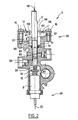
- the rod 6 can thus be pushed axially into a ignition position ( Figure 2) in which a nozzle 82 provided through the rod 6 between the axial cavity 80 and the side wall of the rod 6 opens facing orifice 38.
- the opening 84 no longer communicates with orifice 38.
- the gas arrival path 30 communicates with evacuation route 36 via the cavity 80 and nozzle 82.
- the diameter of the second portion 24 of the bore 18 is significantly larger than that of the rod setting 6.
- the thrust bearing 14, illustrated in FIGS. 13, 14 and 16 is in the form of a steel plate stamped, of generally substantially rectangular shape, endowed with a certain elasticity.
- the stop zone 106 is located between two tabs of fixing 108.
- Each fixing lug 108 comprises a base 116 extending in the longitudinal extension of the zone stop 106.
- the bases 116 are drilled with a hole 110 for the passage of one of the fixing screws 16.
- Each base 116 is connected along two lines of folding 120, with two opposite support wings 118 which have an inclination towards the body 4 relative to the plan of the abutment zone 106 and of the base 116.
- Each wing 118 is separated from the abutment area 106 by a notch 112 going from one edge of the thrust bearing 14 to the fold line 120 associated with this wing 118.
- Each fixing lug 108 thus has a shape arched roof, which gives it properties of elastic deformability in response to the stress of screw 16, which is perpendicular to the plane of the base 116.
- the overlap between the opening 84 and the orifice 38 is such that the opening 84 is offset towards the thrust bearing 14 relative to the orifice 38.
- the area of coincidence 86 would be increased if the axial position stable rod was shifted towards the inside of the body 4.
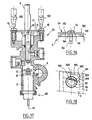
- the calibration process for valve 2 is illustrated in figure 17. It consists in finding the axial position stable of the adjusting rod 6 for which, in a determined angular position of the rod 6, the area of coincidence 86 has the dimensions it takes to leave pass the desired gas flow for this position angular.
- the calibration of valve 2 consists in adjusting the axial position of the thrust bearing 14 relative to the body 4, to the extent permitted by the need to maintain, between the first and second stops axial, an axial gap corresponding to sufficient clearance for the free rotation of the lug 60 between them.
- Figure 18 illustrates the effect of calibration on the area of coincidence 86 which varies between a first segment of disc 186 and a second segment of disc 286.
- the edge oblique 83 of slot 84 sweeps circular hole 38 between two positions 183 and 283, while the other edge oblique 85 of the slot moves between two positions 185 and 285 both located outside orifice 38.
- Adjustment or calibration performed for a position angle of rod 6, is valid for all other angular positions, including the respective bit rates are adjusted accordingly, thanks to the well-defined inclination of the slot 84. This tilt can indeed be very precise without that leads to high manufacturing costs.
- the additional gas path 42 and the second portion boring is only necessary if the device powering includes a pilot light.
- the shoulder 70 is not essential, the spring 68 can rest directly on the ergot 60 on another diametrically opposite lug, made radially more short so as not to interfere with the angular stops 122 and 124.
Landscapes
- Engineering & Computer Science (AREA)
- General Engineering & Computer Science (AREA)
- Mechanical Engineering (AREA)
- Chemical & Material Sciences (AREA)
- Combustion & Propulsion (AREA)
- Lift Valve (AREA)
- Feeding And Controlling Fuel (AREA)
- Taps Or Cocks (AREA)
- Sampling And Sample Adjustment (AREA)
- Valve Housings (AREA)
- Domestic Plumbing Installations (AREA)
Description
- un corps dans lequel est formé un alésage,
- un premier trajet de gaz qui communique avec l'alésage,
- un second trajet de gaz qui est raccordé avec l'alésage par un orifice formé à travers la paroi latérale de l'alésage,
- et un organe de réglage du débit de gaz distribué, comprenant une tige montée pour tourner à l'intérieur dudit alésage dans une position axiale stable, ladite tige comportant une cavité qui communique avec le premier trajet de gaz et qui est munie de moyens de communication qui partent de la cavité et qui débouchent à travers la paroi latérale de la tige en chevauchant l'orifice selon une aire de coïncidence variable au cours de la rotation de la tige,
- on raccorde un des trajets de gaz à une source de gaz,
- on raccorde l'autre trajet de gaz à un appareil de mesure du débit de gaz,
- on place la tige de réglage en une position angulaire prédéterminée,
- on ajuste la position axiale du palier de butée par rapport au corps, jusqu'à ce que le débit mesuré à la sortie du robinet atteigne une valeur prédéterminée souhaitée pour ladite position angulaire prédéterminée de la tige.
- la figure 1 est une vue en coupe axiale d'un robinet selon l'invention, la tige étant représentée dans sa position axiale stable, et dans son orientation correspondant au débit minimal,
- la figure 2 est analogue à la figure 1, la tige étant cette fois en position d'allumage,
- la figure 3 est une vue en coupe axiale du corps du robinet,
- la figure 4 est une coupe transversale du corps du robinet selon le plan de coupe IV-IV de la figure 3,
- la figure 5 est une vue latérale de la tige,
- la figure 6 est une coupe longitudinale de la tige selon VI-VI de la figure 5,
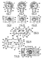
- les figures 7, 9 et 11 sont trois coupes transversales schématiques à travers l'aire de coïncidence entre les moyens de communication de la tige et l'orifice de l'alésage, pour trois positions angulaires de la tige correspondant à trois valeurs de débit de gaz;
- les figures 8, 10 et 12 montrent la situation des figures 7, 9 et 11 respectivement, mais vue selon l'axe de l'orifice,
- les figures 13 et 14 représentent le palier de butée, respectivement en perspective, et en vue de dessous,
- la figure 15 est une coupe transversale du robinet, selon le plan de coupe XV-XV de la figure 1,
- la figure 16 est une coupe latérale partielle montrant la fixation du palier de butée,
- la figure 17 illustre le procédé de calibrage du robinet, et
- la figure 18 illustre l'effet du calibrage sur l'aire de coïncidence.
- on raccorde à une source de gaz le deuxième orifice 34 du trajet d'arrivée de gaz 30,
- on raccorde le quatrième orifice 40 du trajet d'évacuation de gaz 36 à un appareil de mesure du débit de gaz,
- on accouple chaque vis de fixation 16, avec un tournevis 130 pouvant être relié à un moteur commandé, par un asservissement, en fonction de l'écart entre le débit de gaz mesuré et une consigne de débit,
- on alimente l'électro-aimant 8 pour provoquer l'ouverture du clapet 10,
- on place la tige de réglage 6 en une position angulaire prédéterminée, par exemple en première ou en deuxième butée angulaire, ou une position angulaire intermédiaire déterminée comme illustré dans l'exemple de la figure 17,
- on ajuste la position axiale du palier de butée 14 par rapport au corps 4 en serrant progressivement les vis de fixation 16, jusqu'à ce que le débit mesuré à la sortie du robinet 4 atteigne la valeur prédéterminée souhaitée pour ladite position angulaire prédéterminée de la tige de réglage 6.
Claims (19)
- Robinet pour appareil à gaz, et notamment pour appareil de chauffage à catalyse, comprenant :caractérisé en ce que le contour de l'orifice (38) et le contour (83, 85) suivant lequel les moyens de communication (84) débouchent à travers la paroi latérale de la tige (6) sont tels que ladite aire de coïncidence varie de façon continue et progressive au cours de la rotation de la tige (6) à l'intérieur de l'alésage (18).un corps (4) dans lequel est formé un alésage (18),un premier trajet (30) de gaz qui communique avec l'alésage (18),un second trajet (36) de gaz qui est raccordé avec l'alésage (18) par un orifice (38) formé à travers la paroi latérale de l'alésage (18),et un organe de réglage du débit de gaz distribué, comprenant une tige (6) montée pour tourner à l'intérieur dudit alésage (18) dans une position axiale stable, ladite tige (6) comportant une cavité (80) qui communique avec le premier trajet (30) de gaz et qui est munie de moyens de communication (84) qui partent de la cavité (80) et qui débouchent à travers la paroi latérale de la tige (6) en communiquant avec l'orifice (38) selon une aire de coïncidence (86) variable au cours de la rotation de la tige (6) dans la position axiale stable
- Robinet selon la revendication 1, caractérisé en ce qu'il possède une première (122) et une seconde (124) butées angulaires pour limiter la rotation de la tige (6) à l'intérieur de l'alésage (18) de telle manière que ladite aire de coïncidence (86) varie de façon continue et progressive entre une valeur maximale lorsque la tige (6) est contre la première butée angulaire (122) et une valeur minimale non nulle lorsque la tige (6) est contre la seconde butée angulaire (124).
- Robinet selon la revendication 2, caractérisé en ce que la course en rotation de la tige (6) à l'intérieur de l'alésage entre les deux butées angulaires (122, 124) est d'environ 180°.
- Robinet selon la revendication 1, 2 ou 3, caractérisé en ce que les moyens de communication (84) comprennent une fente orientée selon un plan oblique (88) par rapport à l'axe (20) de la tige (6).
- Robinet selon la revendication 4, caractérisé en ce que l'angle d'inclinaison dudit plan oblique (88) par rapport à l'axe (20) de la tige (6) est sensiblement compris entre 88 et 89 degrés.
- Robinet selon la revendication 4 ou 5, caractérisé en ce que la fente présente des bords (83, 85) parallèles.
- Robinet selon la revendication 1, 2 ou 3, caractérisé en ce que les moyens de communication (84) comprennent une ouverture qui chevauche l'orifice (38) de manière variable d'une extrémité à l'autre de la course angulaire de la tige (6) dans sa position axiale stable.
- Robinet selon l'une quelconque des revendications 1 à 7, caractérisé en ce que la tige (6) bénéficie à l'intérieur de l'alésage d'un débattement axial limité par une première butée axiale (106), et en ce qu'il présente un ressort de rappel (68) qui ramène la tige en appui contre la première butée axiale dans ladite position axiale (106) stable de la tige par rapport à l'alésage (18).
- Robinet selon l'une quelconque des revendications précédentes, caractérisé en ce qu'il présente en outre des moyens de calibrage intégrés comprenant des moyens (108) de réglage axial de ladite position axiale stable.
- Robinet selon la revendication 9, caractérisé en ce que lesdits moyens de réglage axial comprennent un palier de butée (14) fixé au corps (4) du robinet, dans une position réglable parallèlement à l'axe (20) de l'alésage (18).
- Robinet selon la revendication 10, caractérisé en ce que le palier de butée comprend au moins deux pattes (108) pour sa fixation par des vis (16) sur le corps (4) du robinet, et en ce que les moyens de réglage axial comprennent une déformabilité des pattes (108) sous l'action desdites vis.
- Robinet selon la revendication 11, caractérisé en ce que pour leur déformabilité les pattes (108) ont une forme cambrée.
- Robinet selon la revendication 10, 11 ou 12, caractérisé en ce que le palier (14) comprend une zone de butée (106) présentant une fenêtre (114) traversée par une partie de la tige (6) qui sort de l'alésage (18), et en ce que la zone de butée coopère avec au moins un ergot (60) disposé sur la paroi latérale de la tige (6) pour réaliser la première butée axiale.
- Robinet selon la revendication 13, caractérisé en ce que des butées angulaires (122, 124) sont disposées sur le palier de butée (14) autour de la fenêtre (114) pour coopérer avec l'ergot (60).
- Robinet selon l'une quelconque des revendications 10 à 14, caractérisé en ce que le corps (4) du robinet présente autour d'une extrémité de l'alésage (18), qui est en regard du palier de butée (14), une face (51) qui forme deuxième butée axiale limitant le débattement axial de la tige (6) à partir de la première butée axiale (106).
- Robinet selon l'une quelconque des revendications 10 à 15, caractérisé en ce que le palier de butée (14) est réalisé sous la forme d'une plaquette en acier matricée.
- Robinet selon l'une quelconque des revendications 1 à 16, caractérisé en ce que, pour une position angulaire déterminée de la tige (6), celle-ci peut coulisser axialement dans l'alésage (18) jusqu'à une position d'allumage éloignée de la position axiale stable, et en ce que ladite tige présente un ajutage (82) qui fait communiquer ledit orifice (38) du corps avec la cavité (80) de la tige (6) lorsque la tige est en position d'allumage.
- Robinet selon l'une quelconque des revendications 1 à 16, caractérisé en ce que la tige (6) présente un ajutage (82) qui communique avec la cavité (80) et qui se trouve en regard de l'orifice (38) du corps, pour une position d'allumage donnée de la tige en rotation et en translation.
- Procédé de calibrage d'un robinet selon l'une quelconque des revendications 10 à 16, caractérisé en ce qu'il comprend les étapes suivantes :on raccorde un (30) des trajets de gaz à une source de gaz,on raccorde l'autre trajet de gaz (36) à un appareil de mesure du débit de gaz,on place la tige de réglage (6) en une position angulaire prédéterminée,on ajuste la position axiale du palier de butée (14) par rapport au corps (4), jusqu'à ce que le débit mesuré à la sortie du robinet atteigne une valeur prédéterminée souhaitée pour ladite position angulaire prédéterminée de la tige.
Applications Claiming Priority (3)
| Application Number | Priority Date | Filing Date | Title |
|---|---|---|---|
| FR9708534A FR2765654B1 (fr) | 1997-07-04 | 1997-07-04 | Robinet pour appareil a gaz, et procede de calibrage d'un tel robinet |
| FR9708534 | 1997-07-04 | ||
| PCT/FR1998/001389 WO1999001700A1 (fr) | 1997-07-04 | 1998-06-30 | Robinet pour appareil a gaz, et procede de calibrage d'un tel robinet |
Publications (2)
| Publication Number | Publication Date |
|---|---|
| EP0993583A1 EP0993583A1 (fr) | 2000-04-19 |
| EP0993583B1 true EP0993583B1 (fr) | 2003-08-06 |
Family
ID=9508898
Family Applications (1)
| Application Number | Title | Priority Date | Filing Date |
|---|---|---|---|
| EP98935061A Expired - Lifetime EP0993583B1 (fr) | 1997-07-04 | 1998-06-30 | Robinet pour appareil a gaz, et procede de calibrage d'un tel robinet |
Country Status (8)
| Country | Link |
|---|---|
| EP (1) | EP0993583B1 (fr) |
| AT (1) | ATE246783T1 (fr) |
| DE (1) | DE69816991T2 (fr) |
| ES (1) | ES2205525T3 (fr) |
| FR (1) | FR2765654B1 (fr) |
| PT (1) | PT993583E (fr) |
| TR (1) | TR199903319T2 (fr) |
| WO (1) | WO1999001700A1 (fr) |
Families Citing this family (2)
| Publication number | Priority date | Publication date | Assignee | Title |
|---|---|---|---|---|
| FR2790065B1 (fr) | 1999-02-22 | 2001-05-18 | Sourdillon Sa | Dispositif de percussion pour une cartouche piezo-electrique et robinet a gaz equipe d'un tel dispositif |
| EP3521701B1 (fr) * | 2018-01-31 | 2021-01-06 | Copreci, S.Coop. | Robinet à gaz avec une soupape de sûreté destinée à un appareil de cuisson au gaz et appareil de cuisson au gaz intégrant ledit robinet à gaz |
Family Cites Families (4)
| Publication number | Priority date | Publication date | Assignee | Title |
|---|---|---|---|---|
| FR27176E (fr) * | 1922-11-27 | 1924-05-19 | Robinets | |
| US2299649A (en) * | 1941-09-12 | 1942-10-20 | Gen Controls Co | Manual reset valve |
| DE1284375B (de) * | 1964-12-02 | 1968-12-05 | Haller Meurer Werke Ag | Gasventil mit thermoelektrischer Zuendsicherung |
| FR2178306A5 (fr) * | 1972-03-27 | 1973-11-09 | Sourdillon Matricage Robinette |
-
1997
- 1997-07-04 FR FR9708534A patent/FR2765654B1/fr not_active Expired - Fee Related
-
1998
- 1998-06-30 DE DE69816991T patent/DE69816991T2/de not_active Expired - Fee Related
- 1998-06-30 WO PCT/FR1998/001389 patent/WO1999001700A1/fr not_active Ceased
- 1998-06-30 ES ES98935061T patent/ES2205525T3/es not_active Expired - Lifetime
- 1998-06-30 EP EP98935061A patent/EP0993583B1/fr not_active Expired - Lifetime
- 1998-06-30 AT AT98935061T patent/ATE246783T1/de not_active IP Right Cessation
- 1998-06-30 PT PT98935061T patent/PT993583E/pt unknown
- 1998-06-30 TR TR1999/03319T patent/TR199903319T2/xx unknown
Also Published As
| Publication number | Publication date |
|---|---|
| FR2765654B1 (fr) | 1999-10-08 |
| WO1999001700A1 (fr) | 1999-01-14 |
| ES2205525T3 (es) | 2004-05-01 |
| ATE246783T1 (de) | 2003-08-15 |
| FR2765654A1 (fr) | 1999-01-08 |
| DE69816991D1 (de) | 2003-09-11 |
| PT993583E (pt) | 2003-12-31 |
| TR199903319T2 (xx) | 2000-04-21 |
| EP0993583A1 (fr) | 2000-04-19 |
| DE69816991T2 (de) | 2004-07-22 |
Similar Documents
| Publication | Publication Date | Title |
|---|---|---|
| EP1241385B1 (fr) | Cartouche thermostatique quart de tour à commandes concentriques, à disques en céramique, et robinet mélangeur muni d'une telle cartouche | |
| CA1065150A (fr) | Detendeur pour briquet a gaz | |
| EP1376292A1 (fr) | Cartouche thermostatique monocommande, à disques en céramique | |
| WO2015052098A1 (fr) | Cartouche thermostatique monocommande | |
| EP2107432A1 (fr) | Dispositif de commande à poussoir pour montre | |
| WO2018042050A1 (fr) | Cartouche thermostatique | |
| FR2625788A1 (fr) | Vanne mitigeuse thermostatique | |
| EP0831261A1 (fr) | Cartouche de robinet mitigeur à limitation ajustable de débit | |
| FR2765654A1 (fr) | Robinet pour appareil a gaz, et procede de calibrage d'un tel robinet | |
| FR2821411A1 (fr) | Cartouche thermostatique a disques en ceramique, du type quart de tour a commandes concentriques, et robinet melangeur muni d'une telle cartouche | |
| EP3845807B1 (fr) | Robinet d'alimentation de gaz ameliore pour bruleur d'un appareil de cuisson a gaz | |
| WO2020115199A1 (fr) | Cartouche thermostatique pour robinet mitigeur | |
| EP0439403B1 (fr) | Robinet mélangeur à temporisation | |
| EP0165281B1 (fr) | Limiteur de debit d'air comprime | |
| FR2500906A1 (fr) | Raccord filete pour une vanne, notamment une vanne de radiateur | |
| FR2520472A1 (fr) | Robinet mitigeur a un seul levier | |
| EP4353998B1 (fr) | Dispositif de commande d'un orifice de distribution de gaz d'un équipement et équipement le comportant | |
| EP1429121A1 (fr) | Dispositif de réglage de débit pour fluides | |
| WO2019228973A1 (fr) | Cartouche thermostatique | |
| EP1317636B1 (fr) | Robinet-detendeur a montage rapide sur une bouteille de gaz | |
| WO1996018070A1 (fr) | Bruleur muni d'un dispositif de commande synchronise | |
| EP0499498B1 (fr) | Vanne d'arrêt en pression à commande manuelle et pneumatique | |
| WO2020115195A1 (fr) | Cartouche thermostatique pour robinet mitigeur | |
| WO2017005581A1 (fr) | Injecteur de carburant avec tarage exterieur du ressort de bobine | |
| FR2561545A1 (fr) | Lance, notamment pour la lutte contre les incendies |
Legal Events
| Date | Code | Title | Description |
|---|---|---|---|
| PUAI | Public reference made under article 153(3) epc to a published international application that has entered the european phase |
Free format text: ORIGINAL CODE: 0009012 |
|
| 17P | Request for examination filed |
Effective date: 20000127 |
|
| AK | Designated contracting states |
Kind code of ref document: A1 Designated state(s): AT DE ES FR GR IT PT |
|
| GRAH | Despatch of communication of intention to grant a patent |
Free format text: ORIGINAL CODE: EPIDOS IGRA |
|
| GRAH | Despatch of communication of intention to grant a patent |
Free format text: ORIGINAL CODE: EPIDOS IGRA |
|
| GRAA | (expected) grant |
Free format text: ORIGINAL CODE: 0009210 |
|
| AK | Designated contracting states |
Designated state(s): AT DE ES FR GR IT PT |
|
| REF | Corresponds to: |
Ref document number: 69816991 Country of ref document: DE Date of ref document: 20030911 Kind code of ref document: P |
|
| RAP2 | Party data changed (patent owner data changed or rights of a patent transferred) |
Owner name: BURNER SYSTEMS INTERNATIONAL (BSI) |
|
| REG | Reference to a national code |
Ref country code: GR Ref legal event code: EP Ref document number: 20030404480 Country of ref document: GR |
|
| REG | Reference to a national code |
Ref country code: ES Ref legal event code: FG2A Ref document number: 2205525 Country of ref document: ES Kind code of ref document: T3 |
|
| REG | Reference to a national code |
Ref country code: FR Ref legal event code: TP Ref country code: FR Ref legal event code: CD |
|
| PLBE | No opposition filed within time limit |
Free format text: ORIGINAL CODE: 0009261 |
|
| STAA | Information on the status of an ep patent application or granted ep patent |
Free format text: STATUS: NO OPPOSITION FILED WITHIN TIME LIMIT |
|
| PG25 | Lapsed in a contracting state [announced via postgrant information from national office to epo] |
Ref country code: AT Free format text: LAPSE BECAUSE OF NON-PAYMENT OF DUE FEES Effective date: 20040630 |
|
| PG25 | Lapsed in a contracting state [announced via postgrant information from national office to epo] |
Ref country code: ES Free format text: LAPSE BECAUSE OF NON-PAYMENT OF DUE FEES Effective date: 20040701 |
|
| 26N | No opposition filed |
Effective date: 20040507 |
|
| PG25 | Lapsed in a contracting state [announced via postgrant information from national office to epo] |
Ref country code: PT Free format text: LAPSE BECAUSE OF NON-PAYMENT OF DUE FEES Effective date: 20041231 |
|
| PG25 | Lapsed in a contracting state [announced via postgrant information from national office to epo] |
Ref country code: DE Free format text: LAPSE BECAUSE OF NON-PAYMENT OF DUE FEES Effective date: 20050101 |
|
| PG25 | Lapsed in a contracting state [announced via postgrant information from national office to epo] |
Ref country code: GR Free format text: LAPSE BECAUSE OF NON-PAYMENT OF DUE FEES Effective date: 20050105 |
|
| PG25 | Lapsed in a contracting state [announced via postgrant information from national office to epo] |
Ref country code: FR Free format text: LAPSE BECAUSE OF NON-PAYMENT OF DUE FEES Effective date: 20050228 |
|
| REG | Reference to a national code |
Ref country code: PT Ref legal event code: MM4A Free format text: LAPSE DUE TO NON-PAYMENT OF FEES Effective date: 20041231 |
|
| REG | Reference to a national code |
Ref country code: FR Ref legal event code: ST |
|
| PG25 | Lapsed in a contracting state [announced via postgrant information from national office to epo] |
Ref country code: IT Free format text: LAPSE BECAUSE OF NON-PAYMENT OF DUE FEES Effective date: 20050630 |
|
| REG | Reference to a national code |
Ref country code: ES Ref legal event code: FD2A Effective date: 20040701 |