EP0993677B1 - Thermosicherung zur fixierung auf einem schaltungssubstrat - Google Patents
Thermosicherung zur fixierung auf einem schaltungssubstrat Download PDFInfo
- Publication number
- EP0993677B1 EP0993677B1 EP98936221A EP98936221A EP0993677B1 EP 0993677 B1 EP0993677 B1 EP 0993677B1 EP 98936221 A EP98936221 A EP 98936221A EP 98936221 A EP98936221 A EP 98936221A EP 0993677 B1 EP0993677 B1 EP 0993677B1
- Authority
- EP
- European Patent Office
- Prior art keywords
- circuit substrate
- contact
- thermal
- point
- snap
- Prior art date
- Legal status (The legal status is an assumption and is not a legal conclusion. Google has not performed a legal analysis and makes no representation as to the accuracy of the status listed.)
- Expired - Lifetime
Links
Images


Classifications
-
- H—ELECTRICITY
- H01—ELECTRIC ELEMENTS
- H01H—ELECTRIC SWITCHES; RELAYS; SELECTORS; EMERGENCY PROTECTIVE DEVICES
- H01H85/00—Protective devices in which the current flows through a part of fusible material and this current is interrupted by displacement of the fusible material when this current becomes excessive
- H01H85/02—Details
- H01H85/04—Fuses, i.e. expendable parts of the protective device, e.g. cartridges
-
- H—ELECTRICITY
- H01—ELECTRIC ELEMENTS
- H01H—ELECTRIC SWITCHES; RELAYS; SELECTORS; EMERGENCY PROTECTIVE DEVICES
- H01H37/00—Thermally-actuated switches
- H01H37/74—Switches in which only the opening movement or only the closing movement of a contact is effected by heating or cooling
- H01H37/76—Contact member actuated by melting of fusible material, actuated due to burning of combustible material or due to explosion of explosive material
- H01H37/761—Contact member actuated by melting of fusible material, actuated due to burning of combustible material or due to explosion of explosive material with a fusible element forming part of the switched circuit
-
- H—ELECTRICITY
- H01—ELECTRIC ELEMENTS
- H01H—ELECTRIC SWITCHES; RELAYS; SELECTORS; EMERGENCY PROTECTIVE DEVICES
- H01H37/00—Thermally-actuated switches
- H01H37/002—Thermally-actuated switches combined with protective means
-
- H—ELECTRICITY
- H05—ELECTRIC TECHNIQUES NOT OTHERWISE PROVIDED FOR
- H05K—PRINTED CIRCUITS; CASINGS OR CONSTRUCTIONAL DETAILS OF ELECTRIC APPARATUS; MANUFACTURE OF ASSEMBLAGES OF ELECTRICAL COMPONENTS
- H05K1/00—Printed circuits
- H05K1/02—Details
- H05K1/0201—Thermal arrangements, e.g. for cooling, heating or preventing overheating
-
- H—ELECTRICITY
- H01—ELECTRIC ELEMENTS
- H01H—ELECTRIC SWITCHES; RELAYS; SELECTORS; EMERGENCY PROTECTIVE DEVICES
- H01H37/00—Thermally-actuated switches
- H01H37/02—Details
- H01H37/04—Bases; Housings; Mountings
- H01H2037/046—Bases; Housings; Mountings being soldered on the printed circuit to be protected
-
- H—ELECTRICITY
- H01—ELECTRIC ELEMENTS
- H01H—ELECTRIC SWITCHES; RELAYS; SELECTORS; EMERGENCY PROTECTIVE DEVICES
- H01H37/00—Thermally-actuated switches
- H01H37/02—Details
- H01H37/32—Thermally-sensitive members
- H01H37/52—Thermally-sensitive members actuated due to deflection of bimetallic element
- H01H37/54—Thermally-sensitive members actuated due to deflection of bimetallic element wherein the bimetallic element is inherently snap acting
- H01H2037/5463—Thermally-sensitive members actuated due to deflection of bimetallic element wherein the bimetallic element is inherently snap acting the bimetallic snap element forming part of switched circuit
-
- H—ELECTRICITY
- H01—ELECTRIC ELEMENTS
- H01H—ELECTRIC SWITCHES; RELAYS; SELECTORS; EMERGENCY PROTECTIVE DEVICES
- H01H37/00—Thermally-actuated switches
- H01H37/02—Details
- H01H37/32—Thermally-sensitive members
- H01H37/52—Thermally-sensitive members actuated due to deflection of bimetallic element
- H01H37/54—Thermally-sensitive members actuated due to deflection of bimetallic element wherein the bimetallic element is inherently snap acting
-
- H—ELECTRICITY
- H05—ELECTRIC TECHNIQUES NOT OTHERWISE PROVIDED FOR
- H05K—PRINTED CIRCUITS; CASINGS OR CONSTRUCTIONAL DETAILS OF ELECTRIC APPARATUS; MANUFACTURE OF ASSEMBLAGES OF ELECTRICAL COMPONENTS
- H05K2201/00—Indexing scheme relating to printed circuits covered by H05K1/00
- H05K2201/10—Details of components or other objects attached to or integrated in a printed circuit board
- H05K2201/10007—Types of components
- H05K2201/10181—Fuse
-
- H—ELECTRICITY
- H05—ELECTRIC TECHNIQUES NOT OTHERWISE PROVIDED FOR
- H05K—PRINTED CIRCUITS; CASINGS OR CONSTRUCTIONAL DETAILS OF ELECTRIC APPARATUS; MANUFACTURE OF ASSEMBLAGES OF ELECTRICAL COMPONENTS
- H05K2203/00—Indexing scheme relating to apparatus or processes for manufacturing printed circuits covered by H05K3/00
- H05K2203/17—Post-manufacturing processes
- H05K2203/176—Removing, replacing or disconnecting component; Easily removable component
-
- H—ELECTRICITY
- H05—ELECTRIC TECHNIQUES NOT OTHERWISE PROVIDED FOR
- H05K—PRINTED CIRCUITS; CASINGS OR CONSTRUCTIONAL DETAILS OF ELECTRIC APPARATUS; MANUFACTURE OF ASSEMBLAGES OF ELECTRICAL COMPONENTS
- H05K3/00—Apparatus or processes for manufacturing printed circuits
- H05K3/30—Assembling printed circuits with electric components, e.g. with resistors
- H05K3/32—Assembling printed circuits with electric components, e.g. with resistors electrically connecting electric components or wires to printed circuits
- H05K3/34—Assembling printed circuits with electric components, e.g. with resistors electrically connecting electric components or wires to printed circuits by soldering
- H05K3/341—Surface mounted components
- H05K3/3421—Leaded components
Definitions
- the invention relates to a thermal fuse for fixing a circuit substrate.
- Such fuses are used to protect circuit parts before thermal overload, especially from surge voltages, and can be used for any circuit, for example Printed circuit boards are used. Preferred area of application However, the thermal fuse according to the invention Layer circuits, in particular thick-film hybrid circuits, such as in telecommunications Find use.
- a thermal fuse of the type mentioned is, for example known from DE 42 19 554 A1.
- the one described there Fuse is a bracket fuse, which is attached to two solder points.
- the thermal fuse is with a defined thick film resistance in the ceramic substrate electrically connected in series. With voltage applied heats the current flowing through the resistance layer the ceramics created by cleverly chosen hot spots at least one of the two soldering points of the fuse is thermal burdened and softens in the event of power overload.
- the bracket lock must first be mechanical after soldering be biased so that a spring clip in case of overload flies away from the softened solder joint and thus the electrical connection breaks.
- Problematic with the known type of fuse is also that the softening process of the solder and associated with it the release of the spring clip or the interruption the current is relatively slow and not abrupt Process is.
- the invention is therefore based on the object of a thermal fuse of the type mentioned at the outset, on the one hand can be used relatively universally for different circuits which, on the other hand, is activated after activation the least possible effort can be reset and the also have a fast and abrupt release behavior should, in the event of a fault, a proper power cut guaranteed.
- the invention is based on a discontinuous method Thermo bimetallic snap element with high-melting solder is mounted on the circuit substrate.
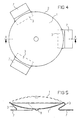
- a bimetallic snap disk 1 provided, on the bulge edge 2 three metallic legs 3 are arranged, the ends of each with high-melting solder in the form of a solder joint on the Circuit substrate 4 (see FIG. 3) are attached, wherein one of the three solder points as the first contact point 5 for connection with a corresponding circuit contact of the circuit substrate 4 is formed.
- the snap disc 1 bowl-shaped down to the circuit substrate 4 mechanically bulged out that at not triggered fuse an electrical connection from the the first contact point 5 soldered the first leg 3 a second contact point 6 of the circuit substrate 4 which rests on the center of the pane.
- the shape change is prevented by the geometry of the disc, the change in shape is given in above this temperature and the bulge after getting enough tension has built up very quickly and abruptly in the other direction vice versa, whereby the electrical contact is released.
- the thermal contact with the circuit substrate 4, for example the ceramic remains above all two of the Maintain legs 3 by being in hot spots of the Substrate 4 are placed.
- the solder joints of the second and third pillar 3 are accordingly on the circuit substrate 4 arranged so that they are in intimate thermal contact with thermal loaded circuit parts, especially sheet resistors, stand. Cools the circuit substrate 4 after Surge voltage off again, the fuse provides the electrical Contact at a lower snap temperature by renewed Fold down the disc curvature again.
- the working temperature range can be easily by the geometric Dimensions of the snap disc 1 can be determined.
- the ceramic heats up over the Legs 3 the snap disc 1. Since this is a relative small size (diameter approx. 1 cm) and thickness (approx. 0.1 mm) this happens very quickly.
- the snap disc 1 folds down and releases the electrical contact. After cooling the electrical contact is automatically restored. If in extreme cases there is a very high temperature load, the two that serve for the thermal connection separate Legs 3, which means no electrical connection after cooling can be restored. advantageously, Even in this extreme case, the thermal fuse does not fall off ceramics, as required by practical application becomes.
- the legs 3 shown in FIGS. 1 to 5 deliver the necessary counterforce so that the snap disc 1 can bulge back and forth due to internal tensions; therefore they must not be too unstable.
- the thermal fuse if - as shown in all figures - the ends of the legs 3 as lying in one plane, forming solder connections Contact tabs 7 are formed. That way they are End of the legs 3 for an SMD assembly and soldering technique suitably designed so that several thermal fuses soldered together in one operation using the reflow process can be.
- the downward towards the circuit substrate 4 domed snap disk center advantageously with a contact lug 8 with gold coating, for example, by embossing.
- a second embodiment of the invention is in the figures 6 to 9 shown.
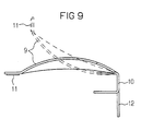
- FIG. 9 works in the same way with regard to the snap effect Way as previously described using the example of the snap disc 1.
- this embodiment is preferably suitable for Forced mounting using the U element 10 (press fit) on the circuit substrate and then soldering with high melting solder.
- the solder joint needs Folding down the fuse does not absorb shear forces and the thermal coupling to the substrate is also on this Way advantageously solved.
- the narrow, opposite the U-element 10 End region 11 of the snap element 9 is by the flipping process from the solid line shown in FIG Touch situation, i.e. the non-activated state, to the position away from the second contact point (reverse arch of the arch). Is shown also an SMD suction gripper integrated in the snap element 9 12th
Landscapes
- Engineering & Computer Science (AREA)
- Microelectronics & Electronic Packaging (AREA)
- Chemical & Material Sciences (AREA)
- Combustion & Propulsion (AREA)
- Fuses (AREA)
- Coupling Device And Connection With Printed Circuit (AREA)
- Thermally Actuated Switches (AREA)
Abstract
Description
- daß ein flächiges Thermobimetall-Schnappelement vorgesehen ist,
- das mit hochschmelzendem Lot durch mindestens eine Lötstelle auf dem Schaltungssubstrat befestigt und das mit dem Schaltungssubstrat thermisch gekoppelt ist,
- wobei die Lötstelle als erste Kontaktstelle zur Verbindung mit einem entsprechenden Schaltungskontakt des Schaltungssubstrats ausgebildet ist,
- und daß das Schnappelement buckelförmig derart mechanisch vorgewölbt ist, daß es bei nicht aktivierter Sicherung eine zweite Kontaktstelle des Schaltungssubstrats elektrisch leitend berührt, bei ausgelöster Sicherung und damit umgekehrter Buckelwölbung jedoch nicht.
- Figur 1 - 5
- zwei Ausführungsbeispiele einer ersten Ausführungsform der Erfindung, wobei Figur 1 eine Draufsicht und Figur 2 und 3 jeweils eine Seitenansicht eines Ausführungsbeispiels im aktivierten (Figur 2) bzw. nicht aktivierten (Figur 3) Zustand der Sicherung zeigt, und Figur 4 und 5 in analoger Darstellung ein zweites Ausführungsbeispiel der ersten Ausführungsform,
- Figur 6 - 9
- eine zweite Ausführungsform der Erfindung, wobei Figur 6 eine Draufsicht, Figur 9 eine Seitenansicht und Figur 7 und 8 jeweils einen Schnitt einer nicht aktivierten Sicherung, wobei in Figur 9 auch der aktivierte Zustand angedeutet ist, zeigen.
Claims (5)
- Thermosicherung zur Fixierung auf einem Schaltungssubstrat,
wobeiein flächiges Thermobimetall-Schnappelement (1, 9) vorgesehen ist,das mit hochschmelzendem Lot durch mindestens eine Lötstelle auf dem Schaltungssubstrat (4) befestigt und das mit dem Schaltungssubstrat (4) thermisch gekoppelt ist,wobei die Lötstelle als erste Kontaktstelle (5) zur Verbindung mit einem entsprechenden Schaltungskontakt des Schaltungssubstrats (4) ausgebildet ist,und wobei das Schnappelement (1, 9) buckelförmig derart mechanisch vorgewölbt ist, daß es bei nicht aktivierter Sicherung eine zweite Kontaktstelle (6) des Schaltungssubstrats (4) elektrisch leitend berührt, bei ausgelöster Sicherung und damit umgekehrter Buckelwölbung jedoch nicht. - Thermosicherung nach Anspruch 1,
dadurch gekennzeichnet, daß eine Thermobimetall-Schnappscheibe (1) vorgesehen ist, an deren Wölbungsrand (2) drei metallische Standbeine (3) angeordnet sind, deren Enden jeweils mit hochschmelzendem Lot in Form einer Lötstelle auf dem Schaltungssubstrat (4) befestigt sind, wobei eine der drei Lötstellen als erste Kontaktstelle (5) zur Verbindung mit einem entsprechenden Schaltungskontakt des Schaltungssubstrats (4) ausgebildet ist, und daß die Schnappscheibe (1) schüsselförmig derart nach unten zum Schaltungssubstrat (4) hin mechanisch vorgewölbt ist, daß bei nicht aktivierter Sicherung eine elektrische Verbindung von dem mit der ersten Kontaktstelle (5) verlöteten ersten Standbein (3) zu einer zweiten Kontaktstelle (6) des Schaltungssubstrats (4), auf der die Scheibenmitte aufliegt, besteht. - Thermosicherung nach Anspruch 2,
dadurch gekennzeichnet, daß die Lötstellen des zweiten und dritten Standbeins (3) auf dem Schaltungssubstrat (4) so angeordnet sind, daß sie in innigem Wärmekontakt mit thermisch belasteten Schaltungsteilen stehen. - Thermosicherung nach Anspruch 2 oder 3,
dadurch gekennzeichnet, daß die Standbeine (3) elastisch ausgebildet sind. - Thermosicherung nach einem der Ansprüche 2 bis 4,
dadurch gekennzeichnet, daß die Enden der Standbeine (3) als in einer Ebene liegende, Lötanschlüsse bildende Kontaktlappen (7) ausgebildet sind.
Applications Claiming Priority (3)
| Application Number | Priority Date | Filing Date | Title |
|---|---|---|---|
| DE19728255 | 1997-07-02 | ||
| DE19728255 | 1997-07-02 | ||
| PCT/DE1998/001678 WO1999001879A1 (de) | 1997-07-02 | 1998-06-18 | Thermosicherung zur fixierung auf einem schaltungssubstrat |
Publications (2)
| Publication Number | Publication Date |
|---|---|
| EP0993677A1 EP0993677A1 (de) | 2000-04-19 |
| EP0993677B1 true EP0993677B1 (de) | 2002-03-06 |
Family
ID=7834419
Family Applications (1)
| Application Number | Title | Priority Date | Filing Date |
|---|---|---|---|
| EP98936221A Expired - Lifetime EP0993677B1 (de) | 1997-07-02 | 1998-06-18 | Thermosicherung zur fixierung auf einem schaltungssubstrat |
Country Status (7)
| Country | Link |
|---|---|
| US (1) | US6342827B1 (de) |
| EP (1) | EP0993677B1 (de) |
| JP (1) | JP2002507318A (de) |
| KR (1) | KR20010014311A (de) |
| CN (1) | CN1123029C (de) |
| DE (1) | DE59803291D1 (de) |
| WO (1) | WO1999001879A1 (de) |
Cited By (2)
| Publication number | Priority date | Publication date | Assignee | Title |
|---|---|---|---|---|
| DE102010038070A1 (de) * | 2010-08-06 | 2012-02-09 | Phoenix Contact Gmbh & Co. Kg | Thermische Überlastschutzvorrichtung |
| US9355801B2 (en) | 2009-06-05 | 2016-05-31 | Marcel P. HOFSAESS | Bimetal part and temperature-dependent switch equipped therewith |
Families Citing this family (14)
| Publication number | Priority date | Publication date | Assignee | Title |
|---|---|---|---|---|
| DE19940543A1 (de) * | 1999-08-26 | 2001-03-01 | Abb Patent Gmbh | Elektrisches Schaltgerät |
| DE502004007603D1 (de) * | 2004-01-28 | 2008-08-28 | Catem Gmbh & Co Kg | Steuereinheit mit thermischem Schutz und eine die Steuereinheit umfassende elektrische Heizvorrichtung |
| KR100571231B1 (ko) * | 2004-05-31 | 2006-04-13 | 삼성에스디아이 주식회사 | 리튬이온전지의 휴즈장치 |
| FR2872335B1 (fr) * | 2004-06-29 | 2006-08-18 | Dav Sa | Microcontacteur electrique pour carte a circuits et interrupteur electrique equipee d'un tel microcontacteur |
| JP4410056B2 (ja) * | 2004-08-04 | 2010-02-03 | 内橋エステック株式会社 | サーモセンサ及びサーモプロテクタ並びにサーモセンサの製作方法 |
| DE102005014601A1 (de) * | 2005-03-31 | 2006-10-05 | Conti Temic Microelectronic Gmbh | Elektronische Baugruppe |
| US8665057B2 (en) * | 2005-03-31 | 2014-03-04 | Conti Temic Microelectronic Gmbh | Electronic assembly having stressable contact bridge with fuse function |
| US7345570B2 (en) * | 2005-08-02 | 2008-03-18 | Uchihashi Estec Co., Ltd. | Thermoprotector |
| US7400225B2 (en) * | 2005-08-30 | 2008-07-15 | Eaton Corporation | Electrical distribution device including protection for overheating conditions |
| DE102009052400B3 (de) * | 2009-11-10 | 2011-05-12 | Phoenix Contact Gmbh & Co. Kg | Thermische Überlastschutzvorrichtung |
| DE102013109291A1 (de) * | 2013-08-27 | 2015-03-05 | Thermik Gerätebau GmbH | Temperaturabhängiger Schalter mit am Rand eingeklemmter Schnappscheibe |
| TWI648759B (zh) * | 2014-05-22 | 2019-01-21 | 聚鼎科技股份有限公司 | 可回焊式溫度保險絲 |
| CN116646217B (zh) * | 2023-06-14 | 2024-02-23 | 佛山市通宝华龙控制器有限公司 | 一种高寿命的双金属碟片的冲孔设备 |
| CN119049920B (zh) * | 2024-09-29 | 2025-09-30 | 东莞市竞沃电子科技有限公司 | 可自恢复的双驱动三端保险器 |
Family Cites Families (18)
| Publication number | Priority date | Publication date | Assignee | Title |
|---|---|---|---|---|
| GB635223A (en) * | 1945-09-19 | 1950-04-05 | Ericsson Telefon Ab L M | Improvements in or relating to thermo-responsive electric switches |
| US2790049A (en) * | 1955-07-11 | 1957-04-23 | Mcgraw Electric Co | Protectors for electric circuits |
| US3529272A (en) * | 1968-05-21 | 1970-09-15 | Fasco Industries | Temperature switch |
| US3638083A (en) * | 1970-08-14 | 1972-01-25 | Sprague Electric Co | Fusible ceramic capacitor |
| US3763454A (en) * | 1972-02-22 | 1973-10-02 | Tektronix Inc | Thermal switch |
| US4536641A (en) * | 1984-01-26 | 1985-08-20 | Black & Decker, Inc. | Iron with overtemperature protection means |
| DE3530921A1 (de) * | 1985-08-29 | 1987-03-12 | Heimann Gmbh | Gasentladungslampe und verfahren zu ihrer herstellung |
| IT1183036B (it) * | 1985-12-04 | 1987-10-05 | Texas Instruments Italia Spa | Dispositivo protettore termico a bimetallo per dispositivi a semiconduttore e simili |
| JPH0244232U (de) * | 1988-09-21 | 1990-03-27 | ||
| DE4209542C2 (de) * | 1992-03-24 | 1995-07-06 | Roederstein Kondensatoren | Schmelzsicherung mit Federarm |
| DE4219554A1 (de) * | 1992-06-15 | 1993-12-16 | Siemens Ag | Thermosicherung und Verfahren zu ihrer Aktivierung |
| AT401125B (de) * | 1992-11-05 | 1996-06-25 | Mikroelektronik Ges Mit Beschr | Verfahren zur herstellung einer thermosicherung |
| JP3233507B2 (ja) * | 1993-08-13 | 2001-11-26 | 株式会社東芝 | 半導体装置 |
| US5358798A (en) * | 1993-12-06 | 1994-10-25 | Motorola, Inc. | Battery assembly having a thermal fuse |
| US5612662A (en) * | 1995-02-07 | 1997-03-18 | Siemens Aktiengesellschaft | Thermal fuse and method for its activation |
| JPH0992110A (ja) * | 1995-09-26 | 1997-04-04 | Denso Corp | 温度ヒューズ付抵抗器 |
| DE19545997C2 (de) * | 1995-12-09 | 1997-12-18 | Marcel Hofsaes | Schalter mit einem temperaturabhängigen Schaltwerk |
| US5896080A (en) * | 1998-04-10 | 1999-04-20 | Kun-Ming Tsai | Thermal fuse for fixing on a circuit board |
-
1998
- 1998-06-18 EP EP98936221A patent/EP0993677B1/de not_active Expired - Lifetime
- 1998-06-18 US US09/462,222 patent/US6342827B1/en not_active Expired - Fee Related
- 1998-06-18 WO PCT/DE1998/001678 patent/WO1999001879A1/de not_active Ceased
- 1998-06-18 KR KR1019997012448A patent/KR20010014311A/ko not_active Withdrawn
- 1998-06-18 JP JP50608799A patent/JP2002507318A/ja active Pending
- 1998-06-18 CN CN98806825A patent/CN1123029C/zh not_active Expired - Fee Related
- 1998-06-18 DE DE59803291T patent/DE59803291D1/de not_active Expired - Fee Related
Cited By (4)
| Publication number | Priority date | Publication date | Assignee | Title |
|---|---|---|---|---|
| US9355801B2 (en) | 2009-06-05 | 2016-05-31 | Marcel P. HOFSAESS | Bimetal part and temperature-dependent switch equipped therewith |
| DE102009061050B4 (de) | 2009-06-05 | 2019-09-05 | Marcel P. HOFSAESS | Bimetallteil und damit ausgestattete temperaturabhängige Schalter |
| DE102010038070A1 (de) * | 2010-08-06 | 2012-02-09 | Phoenix Contact Gmbh & Co. Kg | Thermische Überlastschutzvorrichtung |
| DE102010038070B4 (de) * | 2010-08-06 | 2012-10-11 | Phoenix Contact Gmbh & Co. Kg | Thermische Überlastschutzvorrichtung |
Also Published As
| Publication number | Publication date |
|---|---|
| KR20010014311A (ko) | 2001-02-26 |
| DE59803291D1 (de) | 2002-04-11 |
| WO1999001879A1 (de) | 1999-01-14 |
| CN1123029C (zh) | 2003-10-01 |
| JP2002507318A (ja) | 2002-03-05 |
| CN1261982A (zh) | 2000-08-02 |
| US6342827B1 (en) | 2002-01-29 |
| EP0993677A1 (de) | 2000-04-19 |
Similar Documents
| Publication | Publication Date | Title |
|---|---|---|
| EP0993677B1 (de) | Thermosicherung zur fixierung auf einem schaltungssubstrat | |
| EP0575783B1 (de) | Elektrischer Baustein | |
| DE4428226C1 (de) | Temperaturwächter | |
| DE102013100347B4 (de) | System und verfahren für eine elektronikeinheit mit einem bei ausfall geöffneten mechanismus | |
| DE4437122C2 (de) | Überspannungsschutzstecker | |
| EP0246255B1 (de) | Thermobimetallschalter | |
| DE102009061050B4 (de) | Bimetallteil und damit ausgestattete temperaturabhängige Schalter | |
| EP2740139B1 (de) | Thermische überlastschutzvorrichtung | |
| DE19519462C2 (de) | Wärmeerzeugendes elektrisches Bauteil | |
| WO2012017089A1 (de) | Thermische überlastschutzvorrichtung | |
| EP0756302A2 (de) | Nach dem Baukastenprinzip aufgebauter Temperaturwächter | |
| DE69702719T2 (de) | Elektrische sicherung | |
| EP0740323B1 (de) | Temperaturwächter mit einem bei Übertemperatur schaltenden Bimetall-Schaltwerk | |
| DE3146787A1 (de) | Ueberspannungsableiter mit aeusserer kurzschlussstrecke | |
| EP0285927B1 (de) | Temperaturschalter | |
| DE69928517T2 (de) | Verbesserung bezüglich einer temperaturregelung für elektrische heizelemente | |
| EP1749335B1 (de) | Überspannungsableiter | |
| EP0862197B1 (de) | Schutzstecker | |
| DE2505871A1 (de) | Elektrischer widerstand mit schmelzsicherung | |
| EP1101232B1 (de) | An kontaktflächen eines schaltungssubstrats verlötbares, aus blech geformtes elektrisches bauelement mit lötstop | |
| EP3782172B1 (de) | Thermistor-, varistor- oder kondensator-bauelement mit schmelzbarem verbindungselement zwischen dem grundkörper des bauelements und einer aussenelektrode | |
| WO1997030463A1 (de) | Sicherheitseinrichtung | |
| DE102023104839B3 (de) | Temperaturabhängiger Schalter | |
| DE9402484U1 (de) | Widerstand niederohmiger Bauart mit irreversibler Überlastsicherung | |
| DE102017131432B3 (de) | Anordnung zur thermischen Überwachung von auf einem Verdrahtungsträger befindlichem, elektronischen Bauteil |
Legal Events
| Date | Code | Title | Description |
|---|---|---|---|
| PUAI | Public reference made under article 153(3) epc to a published international application that has entered the european phase |
Free format text: ORIGINAL CODE: 0009012 |
|
| 17P | Request for examination filed |
Effective date: 19991217 |
|
| AK | Designated contracting states |
Kind code of ref document: A1 Designated state(s): BE DE FI FR GB IT NL |
|
| RAP1 | Party data changed (applicant data changed or rights of an application transferred) |
Owner name: TYCO ELECTRONICS LOGISTICS AG |
|
| GRAG | Despatch of communication of intention to grant |
Free format text: ORIGINAL CODE: EPIDOS AGRA |
|
| 17Q | First examination report despatched |
Effective date: 20010426 |
|
| GRAG | Despatch of communication of intention to grant |
Free format text: ORIGINAL CODE: EPIDOS AGRA |
|
| GRAH | Despatch of communication of intention to grant a patent |
Free format text: ORIGINAL CODE: EPIDOS IGRA |
|
| GRAH | Despatch of communication of intention to grant a patent |
Free format text: ORIGINAL CODE: EPIDOS IGRA |
|
| REG | Reference to a national code |
Ref country code: GB Ref legal event code: IF02 |
|
| GRAA | (expected) grant |
Free format text: ORIGINAL CODE: 0009210 |
|
| AK | Designated contracting states |
Kind code of ref document: B1 Designated state(s): BE DE FI FR GB IT NL |
|
| PG25 | Lapsed in a contracting state [announced via postgrant information from national office to epo] |
Ref country code: NL Free format text: LAPSE BECAUSE OF FAILURE TO SUBMIT A TRANSLATION OF THE DESCRIPTION OR TO PAY THE FEE WITHIN THE PRESCRIBED TIME-LIMIT Effective date: 20020306 Ref country code: FI Free format text: LAPSE BECAUSE OF FAILURE TO SUBMIT A TRANSLATION OF THE DESCRIPTION OR TO PAY THE FEE WITHIN THE PRESCRIBED TIME-LIMIT Effective date: 20020306 |
|
| REF | Corresponds to: |
Ref document number: 59803291 Country of ref document: DE Date of ref document: 20020411 |
|
| GBT | Gb: translation of ep patent filed (gb section 77(6)(a)/1977) |
Effective date: 20020517 |
|
| PG25 | Lapsed in a contracting state [announced via postgrant information from national office to epo] |
Ref country code: BE Free format text: LAPSE BECAUSE OF NON-PAYMENT OF DUE FEES Effective date: 20020630 |
|
| NLV1 | Nl: lapsed or annulled due to failure to fulfill the requirements of art. 29p and 29m of the patents act | ||
| ET | Fr: translation filed | ||
| BERE | Be: lapsed |
Owner name: *TYCO ELECTRONICS LOGISTICS A.G. Effective date: 20020630 |
|
| PLBE | No opposition filed within time limit |
Free format text: ORIGINAL CODE: 0009261 |
|
| STAA | Information on the status of an ep patent application or granted ep patent |
Free format text: STATUS: NO OPPOSITION FILED WITHIN TIME LIMIT |
|
| 26N | No opposition filed |
Effective date: 20021209 |
|
| PGFP | Annual fee paid to national office [announced via postgrant information from national office to epo] |
Ref country code: GB Payment date: 20040505 Year of fee payment: 7 |
|
| PGFP | Annual fee paid to national office [announced via postgrant information from national office to epo] |
Ref country code: FR Payment date: 20040602 Year of fee payment: 7 |
|
| PG25 | Lapsed in a contracting state [announced via postgrant information from national office to epo] |
Ref country code: IT Free format text: LAPSE BECAUSE OF NON-PAYMENT OF DUE FEES Effective date: 20050618 Ref country code: GB Free format text: LAPSE BECAUSE OF NON-PAYMENT OF DUE FEES Effective date: 20050618 |
|
| PG25 | Lapsed in a contracting state [announced via postgrant information from national office to epo] |
Ref country code: FR Free format text: LAPSE BECAUSE OF NON-PAYMENT OF DUE FEES Effective date: 20060228 |
|
| GBPC | Gb: european patent ceased through non-payment of renewal fee |
Effective date: 20050618 |
|
| REG | Reference to a national code |
Ref country code: FR Ref legal event code: ST Effective date: 20060228 |
|
| PGFP | Annual fee paid to national office [announced via postgrant information from national office to epo] |
Ref country code: DE Payment date: 20080731 Year of fee payment: 11 |
|
| PG25 | Lapsed in a contracting state [announced via postgrant information from national office to epo] |
Ref country code: DE Free format text: LAPSE BECAUSE OF NON-PAYMENT OF DUE FEES Effective date: 20100101 |