EP0993880A1 - Verfahren zur Herstellung von Walzenständern für Walzgerüste und nach diesem Verfahren hergestellte Walzenständer - Google Patents
Verfahren zur Herstellung von Walzenständern für Walzgerüste und nach diesem Verfahren hergestellte Walzenständer Download PDFInfo
- Publication number
- EP0993880A1 EP0993880A1 EP99119893A EP99119893A EP0993880A1 EP 0993880 A1 EP0993880 A1 EP 0993880A1 EP 99119893 A EP99119893 A EP 99119893A EP 99119893 A EP99119893 A EP 99119893A EP 0993880 A1 EP0993880 A1 EP 0993880A1
- Authority
- EP
- European Patent Office
- Prior art keywords
- housing
- cross
- uprights
- pieces
- welding
- Prior art date
- Legal status (The legal status is an assumption and is not a legal conclusion. Google has not performed a legal analysis and makes no representation as to the accuracy of the status listed.)
- Withdrawn
Links
- 238000000034 method Methods 0.000 title claims abstract description 54
- 238000005096 rolling process Methods 0.000 title claims abstract description 22
- 238000003466 welding Methods 0.000 claims abstract description 36
- 230000008878 coupling Effects 0.000 claims abstract description 20
- 238000010168 coupling process Methods 0.000 claims abstract description 20
- 238000005859 coupling reaction Methods 0.000 claims abstract description 20
- 230000013011 mating Effects 0.000 claims abstract description 5
- 238000005266 casting Methods 0.000 claims description 10
- 230000008569 process Effects 0.000 claims description 8
- 230000003014 reinforcing effect Effects 0.000 claims description 7
- 238000005242 forging Methods 0.000 claims description 5
- 238000012545 processing Methods 0.000 claims description 5
- 230000035515 penetration Effects 0.000 description 15
- 239000000463 material Substances 0.000 description 14
- 230000007547 defect Effects 0.000 description 8
- 230000008901 benefit Effects 0.000 description 4
- 229910000831 Steel Inorganic materials 0.000 description 3
- 239000011324 bead Substances 0.000 description 3
- 238000001816 cooling Methods 0.000 description 3
- 230000009467 reduction Effects 0.000 description 3
- 239000010959 steel Substances 0.000 description 3
- 238000012360 testing method Methods 0.000 description 3
- 229910001018 Cast iron Inorganic materials 0.000 description 2
- XEEYBQQBJWHFJM-UHFFFAOYSA-N Iron Chemical compound [Fe] XEEYBQQBJWHFJM-UHFFFAOYSA-N 0.000 description 2
- 230000007423 decrease Effects 0.000 description 2
- 230000007774 longterm Effects 0.000 description 2
- 238000004519 manufacturing process Methods 0.000 description 2
- 238000010606 normalization Methods 0.000 description 2
- 239000002893 slag Substances 0.000 description 2
- 229910001208 Crucible steel Inorganic materials 0.000 description 1
- 238000007792 addition Methods 0.000 description 1
- 230000000712 assembly Effects 0.000 description 1
- 238000000429 assembly Methods 0.000 description 1
- 230000015572 biosynthetic process Effects 0.000 description 1
- 239000004020 conductor Substances 0.000 description 1
- 230000002950 deficient Effects 0.000 description 1
- 230000001419 dependent effect Effects 0.000 description 1
- 238000011161 development Methods 0.000 description 1
- 238000009826 distribution Methods 0.000 description 1
- 230000008030 elimination Effects 0.000 description 1
- 238000003379 elimination reaction Methods 0.000 description 1
- 230000004907 flux Effects 0.000 description 1
- 239000012535 impurity Substances 0.000 description 1
- 238000005304 joining Methods 0.000 description 1
- 239000006249 magnetic particle Substances 0.000 description 1
- 238000010297 mechanical methods and process Methods 0.000 description 1
- 230000005226 mechanical processes and functions Effects 0.000 description 1
- 238000005272 metallurgy Methods 0.000 description 1
- 238000012986 modification Methods 0.000 description 1
- 230000004048 modification Effects 0.000 description 1
- 231100000817 safety factor Toxicity 0.000 description 1
- 238000010008 shearing Methods 0.000 description 1
- 239000007787 solid Substances 0.000 description 1
- 238000001228 spectrum Methods 0.000 description 1
- 230000003313 weakening effect Effects 0.000 description 1
- 238000005493 welding type Methods 0.000 description 1
Images
Classifications
-
- B—PERFORMING OPERATIONS; TRANSPORTING
- B21—MECHANICAL METAL-WORKING WITHOUT ESSENTIALLY REMOVING MATERIAL; PUNCHING METAL
- B21B—ROLLING OF METAL
- B21B31/00—Rolling stand structures; Mounting, adjusting, or interchanging rolls, roll mountings, or stand frames
- B21B31/02—Rolling stand frames or housings; Roll mountings ; Roll chocks
-
- B—PERFORMING OPERATIONS; TRANSPORTING
- B23—MACHINE TOOLS; METAL-WORKING NOT OTHERWISE PROVIDED FOR
- B23K—SOLDERING OR UNSOLDERING; WELDING; CLADDING OR PLATING BY SOLDERING OR WELDING; CUTTING BY APPLYING HEAT LOCALLY, e.g. FLAME CUTTING; WORKING BY LASER BEAM
- B23K33/00—Specially-profiled edge portions of workpieces for making soldering or welding connections; Filling the seams formed thereby
- B23K33/004—Filling of continuous seams
-
- B—PERFORMING OPERATIONS; TRANSPORTING
- B30—PRESSES
- B30B—PRESSES IN GENERAL
- B30B15/00—Details of, or accessories for, presses; Auxiliary measures in connection with pressing
- B30B15/04—Frames; Guides
Definitions
- This invention concerns a method to make housings for rolling stands and also the housings for rolling stands obtained with this method, as set forth in the respective main claims.
- the invention is employed in the field of metallurgy to make the bearing structure, technically known as the housing, used in rolling trains and processing lines to support and position the rolling rolls.
- the housings used in rolling stands to support and position the rolls have a standardised conformation, substantially quadrilateral, wherein it is possible to distinguish two vertical uprights and two horizontal cross-pieces.
- these housings are produced using mainly two methods.
- a first method provides to cast steel or iron to obtain the housings in their definitive configuration, in single pieces; a second method provides to obtain the housings by means of full penetration welding of steel casts forming the several component parts.
- the first method of producing housings entails a problem of quality connected with the difficulties of obtaining large casts without impurities, porosity and blowholes which are typical of the casting process itself.
- the housing is made using a single material, for example steel or cast iron, while the stresses in the various sections of the housing are somewhat different, reaching higher values at the pass-line, that is, the ideal line of passage of the rolled stock, and in correspondence with the connection zones between the uprights and the cross-pieces.
- any inner defects such as the inclusion of earth, worm holes and porosity can cause cracks, while the housings are in use, which would negatively affect the housing's ability to resist fatigue.
- the second method that is, the one which provides to make housings consisting of component parts made autonomously and then welded together with full penetration steel casts, eliminates in part the disadvantages of the first method, particularly those connected to the high dimensions of the casting.
- Full penetration welding means welding which allows to completely restore the resistant section and wherein, since there is a complete continuity of the two connected pieces, there is a distribution of loads similar to that of a whole piece without any weld.
- the second method however, also has some disadvantages which negatively influence the resistance of the housings, and reduce their working life.
- WO-A-96/26022 describes a housing for rolling stands consisting of uprights and cross-pieces which in turn consist of two parts, respectively an outer part and an inner part, mutually connected by means of reinforcing ribs; in the case of the vertical uprights the reinforcing ribs may also be absent.
- the independent parts which constitute the uprights and cross-pieces define spaces between them, which allow to install conductors, electric cables and devices to support and move the rolls.
- the stand described in WO'022 is configured as a pair of rings, respectively inner and outer, constrained together only in correspondence with the vertical median axis and, optionally, astride the horizontal median axis.
- the reduced thickness of the uprights causes a reduction in the resistant section which is often unacceptable from the point of view of planning, since this reduction affects the average stress which can be supported by the uprights.
- the welding procedure causes difficulties in the correct centering of the elements to be welded.
- a further disadvantage is that the faces of the housings do not have a continuous surface, which creates problems when functional assemblies and accessories have to be attached to said faces.
- the main purpose of the invention is to provide housings with better and longer-lasting quality and mechanical characteristics than those of housings obtained with methods known to the art.
- the housings according to the invention have no problems of porosity, inclusions, residual stresses, diversified cooling and therefore are more reliable and have a longer working life.
- the method according to the invention provides to make the housings in several autonomous parts suitable to be reciprocally welded together by a process of partial penetration welding, that is, wherein the welding partly extends inside the thickness of the housing.
- every housing consists of four parts, two vertical uprights and two horizontal cross-pieces, each part being a substantially monolithic element produced individually by casting, rolling or forging, or even with mixed processes of casting, rolling and forging.
- the inner cavity is through from one side of the housing to the other.
- the inner cavity extends for a length which is less than the thickness of the housing.
- the inner cavity is obtained by combining two semi-holes, open towards the outside, provided in mating and opposite positions on the two coupling surfaces, one on the upright and the other on the cross-piece, to be welded.
- the through cavity is made in a central, or substantially central zone, of the coupling surfaces which are welded to each other, in order not to compromise the centering and the optimum functioning of the housing, in that there are fewer stresses due to the rolling loads in the said central zone.
- the inner cavity in the welding zone allows to improve the quality of the perimeter welds made on the perimeter of the coupling surfaces inasmuch as it limits the penetration thereof to a lesser depth than full penetration welding.
- the first solution provides to take the transverse inner cavity to a defined value of final diameter by means of a mechanical process or removing material, for example by reaming.
- a third solution provides to use, together with the solution with a hole, at least an outer reinforcing ring which is applied on suitable protrusions provided on one or both the front surfaces of the uprights and cross-pieces in correspondence with the relative cavity.
- the method according to the invention has a plurality of advantages compared with methods known to the art.
- the working to size of the transverse inner cavity which is done after welding is completed, taking the final diameter of the cavity to a higher value than the initial value, allows to remove a defined thickness of material which corresponds to the root zone of the weld; in this way any possible defective zones are removed, for example zones containing cracks or similar, which is a great advantage in terms of quality and the inner resistance of the housing.
- the weld material is certainly better in terms of resistance to yield stresses and resilience of the base material used for the housings, and this entails a better behaviour under working conditions of the housing itself in a zone which is particularly subject to stresses.
- the through cavity it is possible, before the pin is inserted or even if no pin is provided, even when the plant is working and without dismantling the stand, to detect possible defects which might be present in the join zones inasmuch as each of these zones can be controlled on four sides, either from outside or from the inside or through the inner cavity, both with surface methods (PT: penetrant test, or MT: magnetic particles test) and also with volume methods (UT: ultrasonic test).
- PT penetrant test
- MT magnetic particles test
- UT ultrasonic test
- the reduced volume of welding involved in joining the parts of the housing compared with the full penetration solution creates fewer residual tensions in the areas of welding.
- the heat to melt the weld material is provided by an arc which strikes between the piece to be welded and the weld material itself.
- the function of protecting the arc is performed by a layer of granular and meltable flux which is deposited above and in front of the arc and which completely covers the melted zone making it invisible to the operator.
- the weld material is in the form of wire wound into a coil which is unwound in a controlled manner.
- the pressure exerted by this pin on the inner surface of the transverse inner cavity is suitable to modify the load spectrum, reducing the amplitude of the stresses ( ⁇ max ).
- the stresses or loads which act on the housing are not continuous, but are characterised by a pulsing development which has a minimum value of ⁇ min when the slab is not passing between the rolls, and therefore no working load is applied, and a maximum value of ⁇ max when a working load is applied.
- the minimum value of ⁇ min is equal to zero, and therefore the amplitude of the stresses, taken as the difference between ⁇ max and ⁇ min , is equal to ⁇ max .
- the value ⁇ min assumes a positive value, different from zero inasmuch as the interference from the pin puts the housing block under tension; therefore, the difference ⁇ max assumes a value which is less than in the case where the pin is not inserted.
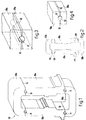
- a housing 10 according to the invention for rolling stands or processing lines comprises four parts, respectively two uprights 10a and two cross-pieces 10b, each made autonomously (Fig. 2) with a process of casting, rolling or forging, or even with a mixed process of casting, rolling and forging.
- respective semi-holes or cavities 111 are provided in corresponding positions, facing each other and open towards the outside.
- the semi-holes 111 have a substantially semi-circular section, but this is only an example, as the semi-holes 111 can have any other different section, for example partly oval, elliptical or similar.
- the semi-holes 111 may be made by means of mechanically removing material, from the individual parts or with the parts already partly coupled, or they may be provided directly in the impressions of the molds.
- Parts 10a and 10b are then coupled together, making the perimeter of the coupling surfaces and the respective semi-holes 111 coincide so as to obtain a housing 10 equipped with four inner cavities 11 passing from side to side of the thickness of the housing 10 in correspondence with each join zone between the uprights 10a and the cross-pieces 10b.
- the method according to the invention then provides that the join zones are welded peripherally together with two welding beads 12 provided on opposite sides with respect to the inner cavity 11.
- the depth of penetration of the welding bead 12 is much less than the depth of a traditional full penetration welding; this gives the advantage of a better quality in terms of a lack of defects such as porosity, inclusions, residual stresses and diversified cooling, and at the same time guarantees the functionality of the housing.
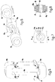
- the method according to the invention provides to take the diameter of the cavity 11 to a defined final value, greater than the initial diameter value, by means of the mechanical removal of material, for example by reaming.
- each ground inner cavity 11 there is inserted, substantially with interference, a reinforcing pin 13 with a section substantially mating with the transverse section of the cavity 11 itself and substantially coinciding in length with the thickness of the housing 10.
- the function of the pin 13 is on the one hand to guarantee the centering and structural continuity of the uprights 10a and the cross-pieces 10b, and on the other hand to eliminate or at least reduce the pulsating component of the stresses deriving from the working loads.
- each of the uprights 10a and the cross-pieces 10b has, in a single body therewith, protrusions 14 facing outwards substantially continuous in form with the respective semi-hole 111.
- the protrusions 14 may be included on one or both the front surfaces of the respective uprights 10a and cross-pieces 10b, just as they may be included both in the upper part and also in the lower part of the rolling stand 10.
Landscapes
- Engineering & Computer Science (AREA)
- Mechanical Engineering (AREA)
- Metal Rolling (AREA)
- Piles And Underground Anchors (AREA)
Applications Claiming Priority (2)
| Application Number | Priority Date | Filing Date | Title |
|---|---|---|---|
| ITUD980178 | 1998-10-15 | ||
| IT1998UD000178A IT1302785B1 (it) | 1998-10-15 | 1998-10-15 | Metodo per la realizzazione di spalle per gabbie dilaminazione e spalle ottenute con tale metodo. |
Publications (1)
| Publication Number | Publication Date |
|---|---|
| EP0993880A1 true EP0993880A1 (de) | 2000-04-19 |
Family
ID=11422763
Family Applications (1)
| Application Number | Title | Priority Date | Filing Date |
|---|---|---|---|
| EP99119893A Withdrawn EP0993880A1 (de) | 1998-10-15 | 1999-10-07 | Verfahren zur Herstellung von Walzenständern für Walzgerüste und nach diesem Verfahren hergestellte Walzenständer |
Country Status (5)
| Country | Link |
|---|---|
| US (1) | US6161413A (de) |
| EP (1) | EP0993880A1 (de) |
| AU (1) | AU5880099A (de) |
| IT (1) | IT1302785B1 (de) |
| WO (1) | WO2000021694A1 (de) |
Cited By (2)
| Publication number | Priority date | Publication date | Assignee | Title |
|---|---|---|---|---|
| ITUD20100066A1 (it) * | 2010-04-08 | 2010-07-08 | Danieli Off Mecc | Telaio di supporto per rulli di una gabbia di laminazione e gabbia di laminazione provvista di tale telaio |
| DE102022207734A1 (de) | 2022-07-27 | 2024-02-01 | Sms Group Gmbh | X-Shape Walzenständerkontur zur Verbesserung des Einschnürverhaltens und Materialeinsatzes (Gewichtsoptimierung) eines Walzenständers |
Families Citing this family (3)
| Publication number | Priority date | Publication date | Assignee | Title |
|---|---|---|---|---|
| IL151728A0 (en) * | 2002-09-12 | 2003-05-29 | Itamar Burstein | A method and a device for securing apparel articles together |
| DE102004008491B4 (de) * | 2004-02-20 | 2012-03-08 | Sms Siemag Aktiengesellschaft | Plattform für Industrieanlagen, insbesondere für Hochdruckentzunderer, Notscheren und Pendelscheren in Walzstraßen, o. dgl. |
| CN111299329B (zh) * | 2020-03-18 | 2024-11-05 | 中冶赛迪装备有限公司 | 一种剖分式轧机牌坊及轧钢机 |
Citations (4)
| Publication number | Priority date | Publication date | Assignee | Title |
|---|---|---|---|---|
| DE829291C (de) * | 1950-04-18 | 1952-03-06 | Erich Schulte | Loesbare Verbindung der Staenderkappe mit dem Staender von Walzgeruesten |
| CH447418A (de) * | 1964-12-11 | 1967-11-30 | Lucas Industries Ltd | Verfahren zum Stumpfschweissen zweier Teile aneinander mittels Elektronenstrahlen |
| JPS58199607A (ja) * | 1982-05-19 | 1983-11-21 | Hitachi Ltd | 圧延機ロールスタンドの製造方法 |
| WO1996026022A1 (en) * | 1995-02-24 | 1996-08-29 | Demag Italimpianti S.P.A. | Shoulder for rolling mill stand with open-type uprights |
Family Cites Families (4)
| Publication number | Priority date | Publication date | Assignee | Title |
|---|---|---|---|---|
| US4107971A (en) * | 1977-06-14 | 1978-08-22 | Textron, Inc. | Cluster type rolling mill |
| DE9415429U1 (de) * | 1994-09-23 | 1994-12-15 | SMS Demag AG, 40237 Düsseldorf | Mehrteiliges Walzgerüst |
| DE19506873C1 (de) * | 1995-02-16 | 1996-07-04 | Mannesmann Ag | Walzenständer in geschlossener Rahmenbauweise |
| US5857372A (en) * | 1997-02-06 | 1999-01-12 | T. Sendzimir, Inc. | Housing for cluster mills |
-
1998
- 1998-10-15 IT IT1998UD000178A patent/IT1302785B1/it active IP Right Grant
-
1999
- 1999-10-07 EP EP99119893A patent/EP0993880A1/de not_active Withdrawn
- 1999-10-07 AU AU58800/99A patent/AU5880099A/en not_active Abandoned
- 1999-10-07 WO PCT/IB1999/001645 patent/WO2000021694A1/en not_active Ceased
- 1999-10-14 US US09/418,357 patent/US6161413A/en not_active Expired - Fee Related
Patent Citations (4)
| Publication number | Priority date | Publication date | Assignee | Title |
|---|---|---|---|---|
| DE829291C (de) * | 1950-04-18 | 1952-03-06 | Erich Schulte | Loesbare Verbindung der Staenderkappe mit dem Staender von Walzgeruesten |
| CH447418A (de) * | 1964-12-11 | 1967-11-30 | Lucas Industries Ltd | Verfahren zum Stumpfschweissen zweier Teile aneinander mittels Elektronenstrahlen |
| JPS58199607A (ja) * | 1982-05-19 | 1983-11-21 | Hitachi Ltd | 圧延機ロールスタンドの製造方法 |
| WO1996026022A1 (en) * | 1995-02-24 | 1996-08-29 | Demag Italimpianti S.P.A. | Shoulder for rolling mill stand with open-type uprights |
Non-Patent Citations (1)
| Title |
|---|
| PATENT ABSTRACTS OF JAPAN vol. 008, no. 043 (M - 279) 24 February 1984 (1984-02-24) * |
Cited By (6)
| Publication number | Priority date | Publication date | Assignee | Title |
|---|---|---|---|---|
| ITUD20100066A1 (it) * | 2010-04-08 | 2010-07-08 | Danieli Off Mecc | Telaio di supporto per rulli di una gabbia di laminazione e gabbia di laminazione provvista di tale telaio |
| WO2011124965A3 (en) * | 2010-04-08 | 2012-01-12 | Danieli & C. Officine Meccaniche Spa | Support frame for rolls of a rolling stand and rolling stand provided with said frame |
| CN103118814A (zh) * | 2010-04-08 | 2013-05-22 | 达涅利机械设备股份公司 | 用于轧机机座内轧辊的支撑框架及具有所述框架的轧机机座 |
| CN103118814B (zh) * | 2010-04-08 | 2015-03-11 | 达涅利机械设备股份公司 | 用于轧机机座内轧辊的支撑框架及具有所述框架的轧机机座 |
| DE102022207734A1 (de) | 2022-07-27 | 2024-02-01 | Sms Group Gmbh | X-Shape Walzenständerkontur zur Verbesserung des Einschnürverhaltens und Materialeinsatzes (Gewichtsoptimierung) eines Walzenständers |
| WO2024022737A1 (de) | 2022-07-27 | 2024-02-01 | Sms Group Gmbh | Walzenständer |
Also Published As
| Publication number | Publication date |
|---|---|
| AU5880099A (en) | 2000-05-01 |
| US6161413A (en) | 2000-12-19 |
| WO2000021694A1 (en) | 2000-04-20 |
| ITUD980178A1 (it) | 2000-04-15 |
| IT1302785B1 (it) | 2000-09-29 |
Similar Documents
| Publication | Publication Date | Title |
|---|---|---|
| KR20150083035A (ko) | 유압 기계용 프란시스형 러너의 제조 방법과 이 방법에 의해서 제조된 러너 | |
| CA1042670A (en) | Method of manufacturing elevator links and a cast elevator link blank for use in the method | |
| US6161413A (en) | Method to make housing for rolling stands and housings obtained with this method | |
| JP2689819B2 (ja) | アクスルハウジングにおけるデフハウジング | |
| JPH0120162Y2 (de) | ||
| DE2608806A1 (de) | Radkoerper mit nabe und verfahren zu seiner herstellung | |
| JPH0435269B2 (de) | ||
| EP0684683B1 (de) | Statorgehäuse und Verfahren zur Herstellung von Statorgehäusen | |
| HU212763B (en) | Method for manufacturing front axle housing for tractors | |
| US6304009B1 (en) | Rotor assembly and method of manufacturing | |
| WO2007045358A1 (en) | Multiple piece roll | |
| CN212685712U (zh) | 一种型材铸件混合型副车架连接结构 | |
| CA1063330A (en) | Method of fabricating hydraulic turbine propeller blade | |
| SU1046001A1 (ru) | Изложница дл отливки слитков | |
| JPH0214853Y2 (de) | ||
| JPH0349797Y2 (de) | ||
| RU11104U1 (ru) | Торцовая стенка барабанной мельницы | |
| Hubman | Welding of Aluminum Castings | |
| JPH11226722A (ja) | 圧延用複合ロール | |
| CN208829159U (zh) | 无磁钢板加强型石油测井用无磁滚筒 | |
| JPS643490Y2 (de) | ||
| IT9067715A1 (it) | Procedimento per la costruzione di un montante per la sospensione della ruota anteriore di un autoveicolo | |
| JPH0255680A (ja) | 鋳物材の電子ビーム溶接方法 | |
| KR101812110B1 (ko) | 수직 밀용 분쇄롤러의 제조방법 | |
| JPH0349798Y2 (de) |
Legal Events
| Date | Code | Title | Description |
|---|---|---|---|
| PUAI | Public reference made under article 153(3) epc to a published international application that has entered the european phase |
Free format text: ORIGINAL CODE: 0009012 |
|
| AK | Designated contracting states |
Kind code of ref document: A1 Designated state(s): AT BE CH CY DE DK ES FI FR GB GR IE IT LI LU MC NL PT SE |
|
| AX | Request for extension of the european patent |
Free format text: AL;LT;LV;MK;RO;SI |
|
| 17P | Request for examination filed |
Effective date: 20001006 |
|
| AKX | Designation fees paid |
Free format text: AT BE CH CY DE DK ES FI FR GB GR IE IT LI LU MC NL PT SE |
|
| AXX | Extension fees paid |
Free format text: SI PAYMENT 20001006 |
|
| 17Q | First examination report despatched |
Effective date: 20020409 |
|
| STAA | Information on the status of an ep patent application or granted ep patent |
Free format text: STATUS: THE APPLICATION IS DEEMED TO BE WITHDRAWN |
|
| 18D | Application deemed to be withdrawn |
Effective date: 20020820 |