EP0993894B1 - Schneiddrahtelektroerosionsmaschine und steuerungsverfahren dafür - Google Patents
Schneiddrahtelektroerosionsmaschine und steuerungsverfahren dafür Download PDFInfo
- Publication number
- EP0993894B1 EP0993894B1 EP98959171A EP98959171A EP0993894B1 EP 0993894 B1 EP0993894 B1 EP 0993894B1 EP 98959171 A EP98959171 A EP 98959171A EP 98959171 A EP98959171 A EP 98959171A EP 0993894 B1 EP0993894 B1 EP 0993894B1
- Authority
- EP
- European Patent Office
- Prior art keywords
- movement
- axis
- electric discharge
- limit
- cut electric
- Prior art date
- Legal status (The legal status is an assumption and is not a legal conclusion. Google has not performed a legal analysis and makes no representation as to the accuracy of the status listed.)
- Expired - Lifetime
Links
Images



Classifications
-
- B—PERFORMING OPERATIONS; TRANSPORTING
- B23—MACHINE TOOLS; METAL-WORKING NOT OTHERWISE PROVIDED FOR
- B23H—WORKING OF METAL BY THE ACTION OF A HIGH CONCENTRATION OF ELECTRIC CURRENT ON A WORKPIECE USING AN ELECTRODE WHICH TAKES THE PLACE OF A TOOL; SUCH WORKING COMBINED WITH OTHER FORMS OF WORKING OF METAL
- B23H7/00—Processes or apparatus applicable to both electrical discharge machining and electrochemical machining
- B23H7/02—Wire-cutting
Definitions
- the present invention relates to a wire cut electric discharge machine which moves one of either a wire electrode or a workpiece with respect to the other in an X-Y plane.
- the present invention relates to a wire cut electric discharge machine capable of forming a taper cut surface in a workpiece by tilting a traveling wire electrode with respect to the X-Y plane.
- either the wire electrode or the workpiece is moved relative to the other within a horizontal plane ("the X-Y plane") determined by two perpendicular axes as the wire electrode travels between a pair of wire guides perpendicular to the X-Y plane.
- the work piece is affixed to a work stand, and the work stand is attached to a table mounted on a bed movable within the X-Y plane.
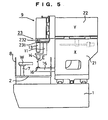
- the wire cut electric discharge machine comprises a bed 1 , a non-moving table 2 mounted on top of the bed 1 , and a movable column 21 .
- a work stand 7 is affixed to the table 2 , and a workpiece W is attached to the work stand 7 .
- a machining tank sidewall 8 which surrounds the workpiece W is also affixed the table 2 .
- a column 21 is mounted on the bed 1 so as to be movable in the X direction, and a ram 22 is mounted on top of the column 21 so as to be movable along the Y axis, which is perpendicular to the X axis.
- a head 9 is provided on the portion of ram 22 which protrudes toward the machining tank side, such that it can move in the Z axis which is perpendicular to the X-Y plane.
- a wire supply device comprising a device to impart tension to a wire electrode E and multiple pulleys is provided on the machining head 9 .
- a taper cut unit 23 formed of sliders 231 and 232 , is provided on the bottom edge of the machining head 9 .
- the slider 231 is movable in the U axis direction which is parallel to the X axis, and the slider 232 is movable in the V axis direction which is parallel to the Y axis.
- upper arm 11 is also attached on one edge to the taper cut unit 23 , and an upper wire guide device 14 is attached to the other end of the upper arm 11 .
- An approximately L-shaped lower arm 15 is affixed at one end to the bottom of the ram 22 , and extends downward in the column 21 through a hole in the ceiling of the column 21 .
- the lower arm 15 next penetrates the sidewall 8 of the horizontally extending machining tank, and a lower wire guide device 16 is attached to the other end of the lower arm 15 .
- the wire electrode E normally moves in the X-Y plane relative to the workpiece W, and travels between the pair of wire guide devices 14 and 16 perpendicular to the X-Y plane.
- machining is usually done by tilting the wire electrode E which travels between the pair of wire guide devices 14 and 16 by some angle away from the Z axis.
- the upper wire guide device 14 moves in the U-V plane which is determined by the orthogonal U and V axes, by means of the taper cut unit 23 .
- the size of the taper cut unit 23 is limited by the machine's rigidity, such that the maximum degree of movement of the upper wire guide device 14 is normally about 70 mm in both the U and V axes.
- FIG. 6 A wire cut electric discharge machine with such features but without a loss of machine rigidity is illustrated in FIG 6 .
- the same reference numerals (as used in FIG. 5 ) are used to designate the same elements as in the wire cut electric discharge machine of FIG. 6 , so an explanation thereof is omitted.
- a mechanical cover 100 which blocks electromagnetic radiation above a certain frequency in accordance with the law, covers the wire cut machine.
- the mechanical cover 100 which blocks electromagnetic radiation above a certain frequency in accordance with EMC (electromagnetic compatibility) regulations, covers the wire cut electric discharge machine.
- a moving body 3 is mounted on a bed 1 so as to be movable along the X axis, and a moving body 4 is mounted on a column 21 so as to be movable along the Y axis which is perpendicular to the X axis.
- the lower arm 15 is supported at one end by a moving body 4 .
- a moving body 5 is mounted on the moving body 4 so as to be movable along the U axis which is parallel to the X axis, and a moving body 6 is mounted on the moving body 5 so as to be movable along the V axis which is parallel to the Y axis.
- a panel 10 is provided on the portion of the moving body 6 which protrudes toward the machining tank side, so as to be movable along the Z axis which is perpendicular to the X-Y plane.
- a wire supply device comprising a wire bobbin 12 , around which is wound the wire electrode E, a device for imparting tension the wire electrode E, and multiple pulleys, is provided on the panel 10 .
- a numerical control device 30 comprising a computer controls movement in the X axis, the Y axis, the U axis, the V axis, and the Z axis directions.
- the wire cut electric discharge machine in FIG. 6 provides a maximum degree of movement for the moving body 5 and the moving body 6 which is greater than that of sliders 231 and 232 in FIG. 5 . In recent wire cut electric discharge machines, a greater maximum degree of movement is sought with respect to the U and V axes, as is a smaller installation footprint.
- a prior art electric discharge machine is known from DE 19600538 , which comprises means for defining a driving area for each workpiece within which an electrode guide may be moved without colliding.
- An object of the present invention is to provide a wire cut electric discharge machine which assures a greater maximum degree of movement with respect to the U and V axes, while at the same time reliably preventing physical striking by movable mechanical components of other mechanical components.
- the invention further provides a method of wire cut electric discharge machining according to claim 2.
- the numerical control device 30 comprises a CPU 31 , a ROM 32 , a RAM 33 , and a memory 34 comprising registers.
- the ROM 32 stores a system program; the CPU controls the entire electric discharge machine in accordance with the system program; the RAM 33 temporarily stores the NC program and the degree of movement in each axial direction, and the memory 34 may comprise, for example, non-volatile memory, and stores limits and the program which checks whether an instructed degree of movement is within those limits.
- a input device 35 comprises a remote control device 35A , a keyboard 35B , and a read device 35C capable of reading out data from a storage medium such as tape or disk.
- the numerical control device 30 further comprises an image processing section 36A which supplies an output signal to a display device 36B such as a CRT, a movement instruction generator 37 , which supplies movement instructions to the respective motor drivers which drive the motors, and a limit determination section 38 which receives the movement instruction and determines whether the degree of movement is within the limit.
- the movement instruction generator 37 reads the NC program block by block and obtains the machining path to supply movement instructions required for that machining path through the limit determination section 38 to an appropriate motor driver 39 . In the illustrated embodiment, only one combination of a motor 40A and a motor driver 39 is shown; other combinations are omitted.
- a encoder 40B attached to the motor 40A sends a signal indicating the present degree of movement to the limit determination section 38 through the motor driver 39 .
- the input device 35, ROM 32, RAM 33, memory 34, image processing section 36A, movement instruction generator 37 , and limit determination section 38 are connected to the CPU 31 through an address-data bus line 41 .
- the movement instruction generator 37 When the movement instruction generator 37 receives a manual data input ("MDI") signal or an NC program under control of the CPU 31, it supplies a movement instruction to the limit determination section 38 .
- the limit determination section 38 determines that the instructed degree of movement exceeds the limits, it does not supply that movement instruction to the motor driver 39 , and requests error processing from the CPU 31.
- the flow chart in FIG. 3 shows the process by which the numerical control device 30 checks whether the NC program contains movements which exceed the limits.
- the program which performs the limit check is stored in the memory 34 .
- the table or pair of wire guides to which the workpiece is attached move in accordance with the NC program, but, preferably, the workpiece is not machined.
- the limit set is stored in the memory 34 at step S71 .
- a lower limit a and upper limit b for the sum of the X axis degree of movement x and the U axis degree of movement u, and a lower limit c and upper limit d for the sum of the Y axis degree of movement y and V axis degree of movement v are set.
- the U axis direction is parallel to the X axis direction
- the V axis direction is parallel to the Y axis direction.
- the movement instruction generator 37 reads the NC program temporarily stored in the RAM 33 for each block at step S72 , generating a movement instruction.
- This movement instruction is provided to the limit determination section 38 while also being sorted in the RAM 33.
- the process is completed when the movement instruction generator 37 has read all program blocks of the NC program at step S73 . Otherwise the process proceeds to step S74 , and the limit determination section 38 , in accordance with the program stored in the memory 34 , finds the sum of the instructed degree of movement in a certain axis and the current degree of movement in another axis parallel to the certain axis. For example, when the received movement instruction indicates a degree of movement in the U axial direction, the limit determination section 38 finds the sum x + u of the instructed degree of movement u and the X axial direction current degree of movement x.
- step S75 the limit determination section 38 determines whether the sum x + u is within the limits a and b.
- the machining path is displayed on the display 36B at step S76 , and the process returns to step 73 . Otherwise, machine movement stops at step S77 , and a message indicating an NC program error is generated at step S78 and displayed on the display 36B .
- the flow chart in FIG. 4 illustrates the process carried out by the numerical control device 30 when the movement instructions supplied are not in the NC program format, but from the remote control device 35A or the keyboard 35B to the motor driver 39 .
- This movement instruction is valid only so long as the "JOG" key is depressed after, for example, a motion speed designation.
- the input devices 35A or 35B have several "JOG” keys in accordance with the number of movement directions; e.g. X axis "+" and "-".
- the set limit is first stored in the memory 34 at step S81 .
- the limit determination section 38 reads the current degree of movement in the x, y, u and v directions for the X, Y, U, and V axes from the encoders 40B at step S82 , and finds the degree of movement sums x + u and y + v at step S83 . If it is determined at step S84 that the sum x + u is not between the limits a and b or the sum y + v is not between the limits c and d, machine movement is halted at step S85 and a message indicating "limit exceeded" appears on the display device 36B at step S86 . Otherwise, the process proceeds to step S87 . When the movement instruction is valid, the process returns to step S82 .
- the limit determination section 38 may be connected only to the movement instruction generator 37 . In that case, when the limit determination section 38 receives a movement instruction from the movement instruction generator 37 , it supplies a signal indicating the determination result to the CPU 31 through the movement instruction generator 37 .
Landscapes
- Chemical & Material Sciences (AREA)
- Chemical Kinetics & Catalysis (AREA)
- Electrochemistry (AREA)
- Engineering & Computer Science (AREA)
- Mechanical Engineering (AREA)
- Electrical Discharge Machining, Electrochemical Machining, And Combined Machining (AREA)
- Automatic Control Of Machine Tools (AREA)
- Auxiliary Devices For Machine Tools (AREA)
Claims (2)
- Schneiddraht-Elektroerosionsmaschine, die ein Werkstück durch Generieren einer elektrischen Entladung zwischen einer wandernden Drahtelektrode und dem Werkstück bearbeitet; die Schneiddraht-Elektroerosionsmaschine umfasst:ein erstes in einer X-Y-Ebene bewegbares Teil, das senkrechte X- und Y-Achsen umfasst;ein zweites Teil, das in einer U-V-Ebene bewegbar ist, das eine U-Achse parallel zur X-Achse und eine V-Achse parallel zur Y-Achse umfasst; undeine Steuereinrichtung, die eine CPU (31) und einen Bewegungsinstruktionsgenerator (37) umfasst, der Bewegungsinstruktionen an einen Motortreiber (39) zur Bewegung der ersten und zweiten Teile liefert,dadurch gekennzeichnet, dass die Steuereinrichtung weiter einen Abschnitt (38) für instruierte Grenzwertermittlung umfasst, der angepasst ist, Bewegungsinstruktionen vom Bewegungsinstruktionsgenerator (37) zu empfangen, um die Summe des instruierten Bewegungsgrads des ersten Teils in der axialen X-Richtung und den instruierten Bewegungsgrad des zweiten Teils in der axialen U-Richtung mit einem gespeicherten Grenzwert zu vergleichen und die Bewegungsinstruktionen nur an den Motortreiber zu liefern, wenn besagte Summe innerhalb besagten Grenzwerts liegt unddie Bewegung der Schneiddraht-Elektroerosionsmaschine durch Nichtlieferung der Bewegungsinstruktion and den Motortreiber zu stoppen, wenn besagte Summe einen Grenzwert überschreitet und Fehlerbearbeitung von der CPU (31) zu erbitten.
- Bearbeitungsverfahren für Schneiddraht-Elektoerosion unter Einsatz einer Maschine, wie in Anspruch 1 beansprucht, wobei das Verfahren umfasst:Instruieren von Bewegung in zumindest einer der axialen ersten X- und zweiten U-Richtungen;Ermitteln des instruierten Bewegungsgrads in den axialen ersten und zweiten Bewegungsrichtungen;gekennzeichnet durch Einsatz des Abschnitts (38) für Grenzwertermittlung, um die Summe der zwei erkannten instruierten Bewegungsgrade mit einem Grenzwert zu vergleichen;und Stoppen der Bewegung in zumindest einer der Achsen, wenn besagte Summe den Grenzwert überschreitet, durch Nichtlieferung von Bewegungsinstruktionen an den Motortreiber (39) und Erbitten von Fehlerbearbeitung von der CPU (31).
Applications Claiming Priority (3)
| Application Number | Priority Date | Filing Date | Title |
|---|---|---|---|
| JP34166497 | 1997-12-11 | ||
| JP9341664A JPH11170117A (ja) | 1997-12-11 | 1997-12-11 | 工作機械の移動軸の制御方法及び装置 |
| PCT/JP1998/005608 WO1999029458A1 (fr) | 1997-12-11 | 1998-12-11 | Appareil de sectionnement de fils par decharge electrique et son procede de commande |
Publications (3)
| Publication Number | Publication Date |
|---|---|
| EP0993894A1 EP0993894A1 (de) | 2000-04-19 |
| EP0993894A4 EP0993894A4 (de) | 2004-07-14 |
| EP0993894B1 true EP0993894B1 (de) | 2011-01-26 |
Family
ID=18347841
Family Applications (1)
| Application Number | Title | Priority Date | Filing Date |
|---|---|---|---|
| EP98959171A Expired - Lifetime EP0993894B1 (de) | 1997-12-11 | 1998-12-11 | Schneiddrahtelektroerosionsmaschine und steuerungsverfahren dafür |
Country Status (6)
| Country | Link |
|---|---|
| US (1) | US6278076B1 (de) |
| EP (1) | EP0993894B1 (de) |
| JP (1) | JPH11170117A (de) |
| CN (1) | CN1100639C (de) |
| DE (1) | DE69842111D1 (de) |
| WO (1) | WO1999029458A1 (de) |
Families Citing this family (12)
| Publication number | Priority date | Publication date | Assignee | Title |
|---|---|---|---|---|
| WO2000062966A1 (es) * | 1999-04-16 | 2000-10-26 | Ona Electro-Erosion, S.A. | Maquina de electroerosion por hilo |
| JP4041261B2 (ja) * | 2000-03-10 | 2008-01-30 | 株式会社ソディック | ワイヤ放電加工機 |
| CN100425381C (zh) * | 2005-09-21 | 2008-10-15 | 上海大量电子设备有限公司 | 一种电火花线切割机 |
| JP4221016B2 (ja) | 2006-07-25 | 2009-02-12 | ファナック株式会社 | 干渉チェックを行う数値制御装置 |
| KR101575780B1 (ko) * | 2008-07-10 | 2015-12-08 | 시티즌 마쉬나리 가부시키가이샤 | 간섭 체크 장치 및 간섭 체크 방법 및 간섭 체크 장치를 갖춘 공작기계 |
| US9452482B2 (en) * | 2011-04-19 | 2016-09-27 | Kurashiki System Design Co., Ltd. | Electrical discharge machine |
| JP2014200864A (ja) * | 2013-04-02 | 2014-10-27 | ファナック株式会社 | ワイヤ電極張力制御機能を有するワイヤ放電加工機 |
| JP5977290B2 (ja) * | 2014-07-30 | 2016-08-24 | ファナック株式会社 | 誤加工防止機能を備えたワイヤ放電加工機 |
| JP6548889B2 (ja) * | 2014-10-27 | 2019-07-24 | 共立精機株式会社 | ツールプリセッターに於ける衝突防止装置 |
| JP6017096B1 (ja) * | 2015-10-30 | 2016-10-26 | 三菱電機株式会社 | ワイヤ放電加工機、ワイヤ放電加工機の制御装置の制御方法及び位置決め方法 |
| CN109411160B (zh) * | 2017-08-16 | 2023-09-12 | 厦门海普锐科技股份有限公司 | 一种多管径自动穿套号码管装置 |
| CN108380989B (zh) * | 2018-03-28 | 2024-04-23 | 北京汉飞航空科技有限公司 | 一种航空发动机整体叶盘的加工方法及设备 |
Family Cites Families (13)
| Publication number | Priority date | Publication date | Assignee | Title |
|---|---|---|---|---|
| JPS5766824A (en) * | 1980-10-08 | 1982-04-23 | Fanuc Ltd | Tapered processing method in wire cutting discharge processing machine |
| JPS61288929A (ja) * | 1985-06-15 | 1986-12-19 | Fanuc Ltd | ワイヤカツト放電加工機 |
| JPS62120919A (ja) * | 1985-11-20 | 1987-06-02 | Fanuc Ltd | ワイヤカツト放電加工方法 |
| JPS62213923A (ja) * | 1986-03-14 | 1987-09-19 | Hitachi Seiko Ltd | ワイヤ放電加工機 |
| JP2578128B2 (ja) * | 1987-09-17 | 1997-02-05 | 株式会社アマダ | ワイヤ放電加工装置 |
| JP2620862B2 (ja) * | 1987-10-30 | 1997-06-18 | ファナック株式会社 | ワイヤ放電加工機による大テーパ加工方法 |
| JPH02152748A (ja) | 1988-12-02 | 1990-06-12 | Mitsubishi Electric Corp | 数値制御用工作機械のストロークエンドチェック装置 |
| JPH02279220A (ja) * | 1989-04-19 | 1990-11-15 | Mitsubishi Electric Corp | ワイヤ放電加工装置 |
| US5003147A (en) * | 1989-05-12 | 1991-03-26 | Brother Kogyo Kabushiki Kaisha | Method of measuring wire guide spans and directing wire electrode perpendicularly to reference machining plane in electrical-discharge wire cutting machine |
| JP3223723B2 (ja) * | 1994-09-20 | 2001-10-29 | 三菱電機株式会社 | ワイヤ放電加工装置及びその制御方法 |
| DE19506775C2 (de) * | 1995-02-27 | 1997-09-25 | Agie Ag Ind Elektronik | Vorrichtung zum Führen einer Bearbeitungselektrode an einer Funkenerosionsmaschine |
| JP3570006B2 (ja) | 1995-05-19 | 2004-09-29 | 三菱電機株式会社 | 放電加工機 |
| DE19600538A1 (de) * | 1996-01-09 | 1997-07-10 | Agie Ag Ind Elektronik | Verfahren und Vorrichtung zur Steuerung einer Funkenerosionsmaschine |
-
1997
- 1997-12-11 JP JP9341664A patent/JPH11170117A/ja active Pending
-
1998
- 1998-12-11 US US09/355,911 patent/US6278076B1/en not_active Expired - Lifetime
- 1998-12-11 EP EP98959171A patent/EP0993894B1/de not_active Expired - Lifetime
- 1998-12-11 CN CN98801844A patent/CN1100639C/zh not_active Expired - Lifetime
- 1998-12-11 DE DE69842111T patent/DE69842111D1/de not_active Expired - Lifetime
- 1998-12-11 WO PCT/JP1998/005608 patent/WO1999029458A1/ja not_active Ceased
Also Published As
| Publication number | Publication date |
|---|---|
| CN1100639C (zh) | 2003-02-05 |
| US6278076B1 (en) | 2001-08-21 |
| DE69842111D1 (de) | 2011-03-10 |
| WO1999029458A1 (fr) | 1999-06-17 |
| EP0993894A4 (de) | 2004-07-14 |
| JPH11170117A (ja) | 1999-06-29 |
| EP0993894A1 (de) | 2000-04-19 |
| CN1243466A (zh) | 2000-02-02 |
Similar Documents
| Publication | Publication Date | Title |
|---|---|---|
| EP0993894B1 (de) | Schneiddrahtelektroerosionsmaschine und steuerungsverfahren dafür | |
| EP1195665B1 (de) | Vorrichtung und Verfahren zur Bestimmung von Steuerungsparametern einer maschinellen Vorrichtung | |
| EP0105158A2 (de) | Schnittstelle zur untergeordneten Programmänderung in einem numerisch gesteuerten System | |
| KR100421789B1 (ko) | 수치제어명령작성장치및방법 | |
| EP0529239B1 (de) | Numerische Steuerungseinheit mit Positionszählersteuerung und Anzeige | |
| EP0107147B1 (de) | Numerisch gesteuerter Prozess und nach diesem Prozess arbeitende Maschine | |
| JPH03178731A (ja) | 放電加工装置 | |
| US4891487A (en) | Electrode return control for electric spark machine | |
| HK1004296B (en) | Numerical control unit with position counter control and display | |
| US4644124A (en) | Wire electrode type electrical discharge machining method | |
| JP4451708B2 (ja) | 誤加工防止装置および誤加工防止方法 | |
| JP2885228B2 (ja) | ワイヤ放電加工方法及び装置 | |
| CN121100040A (zh) | 数值控制装置和数值控制程序 | |
| EP0649697A1 (de) | Vorrichtung zum elektroerosiven bearbeiten und maschinenzustandseinstellverfahren | |
| US6690983B2 (en) | Numerical control data creating device and numerical control data creating method | |
| JP4661494B2 (ja) | 数値制御装置 | |
| JPS6253291B2 (de) | ||
| JP2637478B2 (ja) | V字形状溝加工機の切込み軸制御方法 | |
| JP4348791B2 (ja) | ワイヤ放電加工機及びワイヤ放電加工機の原点復帰方法 | |
| KR19990045935A (ko) | 외장형고속/고정도가공제어시스템 | |
| KR100372367B1 (ko) | 영역가공 운전용 제어장치 | |
| JPH0623614A (ja) | 簡易描画機 | |
| JPH0592349A (ja) | 数値制御装置 | |
| JPH08150540A (ja) | 工作機械の干渉防止装置 | |
| CN120715688A (zh) | 加工装置、控制方法及程序产品 |
Legal Events
| Date | Code | Title | Description |
|---|---|---|---|
| PUAI | Public reference made under article 153(3) epc to a published international application that has entered the european phase |
Free format text: ORIGINAL CODE: 0009012 |
|
| 17P | Request for examination filed |
Effective date: 19991030 |
|
| AK | Designated contracting states |
Kind code of ref document: A1 Designated state(s): DE FR GB IT |
|
| A4 | Supplementary search report drawn up and despatched |
Effective date: 20040601 |
|
| RIC1 | Information provided on ipc code assigned before grant |
Ipc: 7B 23H 7/20 B Ipc: 7B 23H 7/06 B Ipc: 7B 23H 1/02 A |
|
| 17Q | First examination report despatched |
Effective date: 20070403 |
|
| GRAP | Despatch of communication of intention to grant a patent |
Free format text: ORIGINAL CODE: EPIDOSNIGR1 |
|
| GRAJ | Information related to disapproval of communication of intention to grant by the applicant or resumption of examination proceedings by the epo deleted |
Free format text: ORIGINAL CODE: EPIDOSDIGR1 |
|
| GRAP | Despatch of communication of intention to grant a patent |
Free format text: ORIGINAL CODE: EPIDOSNIGR1 |
|
| GRAS | Grant fee paid |
Free format text: ORIGINAL CODE: EPIDOSNIGR3 |
|
| GRAA | (expected) grant |
Free format text: ORIGINAL CODE: 0009210 |
|
| AK | Designated contracting states |
Kind code of ref document: B1 Designated state(s): DE FR GB IT |
|
| REG | Reference to a national code |
Ref country code: GB Ref legal event code: FG4D |
|
| REF | Corresponds to: |
Ref document number: 69842111 Country of ref document: DE Date of ref document: 20110310 Kind code of ref document: P |
|
| REG | Reference to a national code |
Ref country code: DE Ref legal event code: R096 Ref document number: 69842111 Country of ref document: DE Effective date: 20110310 |
|
| PLBE | No opposition filed within time limit |
Free format text: ORIGINAL CODE: 0009261 |
|
| STAA | Information on the status of an ep patent application or granted ep patent |
Free format text: STATUS: NO OPPOSITION FILED WITHIN TIME LIMIT |
|
| 26N | No opposition filed |
Effective date: 20111027 |
|
| REG | Reference to a national code |
Ref country code: DE Ref legal event code: R097 Ref document number: 69842111 Country of ref document: DE Effective date: 20111027 |
|
| PG25 | Lapsed in a contracting state [announced via postgrant information from national office to epo] |
Ref country code: IT Free format text: LAPSE BECAUSE OF FAILURE TO SUBMIT A TRANSLATION OF THE DESCRIPTION OR TO PAY THE FEE WITHIN THE PRESCRIBED TIME-LIMIT Effective date: 20110126 |
|
| REG | Reference to a national code |
Ref country code: FR Ref legal event code: ST Effective date: 20120831 |
|
| PG25 | Lapsed in a contracting state [announced via postgrant information from national office to epo] |
Ref country code: FR Free format text: LAPSE BECAUSE OF NON-PAYMENT OF DUE FEES Effective date: 20120102 |
|
| PGFP | Annual fee paid to national office [announced via postgrant information from national office to epo] |
Ref country code: DE Payment date: 20171211 Year of fee payment: 20 |
|
| PGFP | Annual fee paid to national office [announced via postgrant information from national office to epo] |
Ref country code: GB Payment date: 20171221 Year of fee payment: 20 |
|
| REG | Reference to a national code |
Ref country code: DE Ref legal event code: R071 Ref document number: 69842111 Country of ref document: DE |
|
| REG | Reference to a national code |
Ref country code: GB Ref legal event code: PE20 Expiry date: 20181210 |
|
| PG25 | Lapsed in a contracting state [announced via postgrant information from national office to epo] |
Ref country code: GB Free format text: LAPSE BECAUSE OF EXPIRATION OF PROTECTION Effective date: 20181210 |