EP0993900A2 - Vorrichtung zum Prüfen und Einrichten von Arbeitsstationen - Google Patents
Vorrichtung zum Prüfen und Einrichten von Arbeitsstationen Download PDFInfo
- Publication number
- EP0993900A2 EP0993900A2 EP99120425A EP99120425A EP0993900A2 EP 0993900 A2 EP0993900 A2 EP 0993900A2 EP 99120425 A EP99120425 A EP 99120425A EP 99120425 A EP99120425 A EP 99120425A EP 0993900 A2 EP0993900 A2 EP 0993900A2
- Authority
- EP
- European Patent Office
- Prior art keywords
- control
- production range
- workpieces
- functions
- testing
- Prior art date
- Legal status (The legal status is an assumption and is not a legal conclusion. Google has not performed a legal analysis and makes no representation as to the accuracy of the status listed.)
- Granted
Links
Images

Classifications
-
- G—PHYSICS
- G05—CONTROLLING; REGULATING
- G05B—CONTROL OR REGULATING SYSTEMS IN GENERAL; FUNCTIONAL ELEMENTS OF SUCH SYSTEMS; MONITORING OR TESTING ARRANGEMENTS FOR SUCH SYSTEMS OR ELEMENTS
- G05B19/00—Program-control systems
- G05B19/02—Program-control systems electric
- G05B19/418—Total factory control, i.e. centrally controlling a plurality of machines, e.g. direct or distributed numerical control [DNC], flexible manufacturing systems [FMS], integrated manufacturing systems [IMS] or computer integrated manufacturing [CIM]
- G05B19/41885—Total factory control, i.e. centrally controlling a plurality of machines, e.g. direct or distributed numerical control [DNC], flexible manufacturing systems [FMS], integrated manufacturing systems [IMS] or computer integrated manufacturing [CIM] characterised by modeling, simulation of the manufacturing system
-
- G—PHYSICS
- G05—CONTROLLING; REGULATING
- G05B—CONTROL OR REGULATING SYSTEMS IN GENERAL; FUNCTIONAL ELEMENTS OF SUCH SYSTEMS; MONITORING OR TESTING ARRANGEMENTS FOR SUCH SYSTEMS OR ELEMENTS
- G05B2219/00—Program-control systems
- G05B2219/30—Nc systems
- G05B2219/31—From computer integrated manufacturing till monitoring
- G05B2219/31078—Several machines and several buffers, storages, conveyors, robots
-
- Y—GENERAL TAGGING OF NEW TECHNOLOGICAL DEVELOPMENTS; GENERAL TAGGING OF CROSS-SECTIONAL TECHNOLOGIES SPANNING OVER SEVERAL SECTIONS OF THE IPC; TECHNICAL SUBJECTS COVERED BY FORMER USPC CROSS-REFERENCE ART COLLECTIONS [XRACs] AND DIGESTS
- Y02—TECHNOLOGIES OR APPLICATIONS FOR MITIGATION OR ADAPTATION AGAINST CLIMATE CHANGE
- Y02P—CLIMATE CHANGE MITIGATION TECHNOLOGIES IN THE PRODUCTION OR PROCESSING OF GOODS
- Y02P90/00—Enabling technologies with a potential contribution to greenhouse gas [GHG] emissions mitigation
- Y02P90/02—Total factory control, e.g. smart factories, flexible manufacturing systems [FMS] or integrated manufacturing systems [IMS]
Definitions
- the invention relates to a device for testing and Setting up workstations with the features in Preamble of the main claim.
- production plants are with one or known to several workstations in which workpieces, in particular body shells of vehicles, of components built, assembled, tensioned and processed, in particular be welded.
- workpieces in particular body shells of vehicles
- components built, assembled, tensioned and processed in particular be welded
- workstations one or more production ranges in use, the different tools, especially clamping but also Machining tools, wear and if necessary Workpieces, e.g. Body components, feed.
- Such Production ranges are highly complex devices whose Development very closely with the parallel one Vehicle development is coupled.
- an emaciated test range is used, which is equipped with a simulation device to simulate the functions of the real production range.
- the components of the work station or their periphery and in particular the one or more associated controls can be set up and checked parallel to the development of the vehicle and pallet. In particular, the entire system can be tested in interaction through the simulated pallet functions.
- the range of tests enables programming of the overall system with a larger one available Timeframes are carried out. This affects e.g. the Programming the line control, the Transport technology control, the interaction with the respective control of the processing devices, especially the robot controls, the programming all locks, interfaces between the Line control and transport technology control etc. From Another advantage is that the real production range can be kept out of the line for a long time until the correct components are available. The production range can thus on the components outside the production line be adjusted and thus comes as a complete and tested production range in the system. The last Activities with this range of products are limited then just checking on Collision problems, geometrical accuracy of the welding spots, Verification of cycle time etc.
- the simulation device exists advantageously from one or more programmable Controls in which the functions of the palette and their Parts depending on the planned production process are saved. It is advantageous if the Control multiple program memories for different Has pallet and workpiece types. This is the Test range can be used multiple times.
- test range is up to the final tool or Workpiece assignment of the real production range in the decisive points for the interaction with the Workstation and its parts reproduced.
- test palette has the external form, the mechanical one Interfaces and at least one connection for the Equipment according to the real production range.
- a work station (1) is schematic shown, which is integrated in a transfer line (16) is.
- the workstation (1) shown can be seen on the left and connect further workstations on the right.
- the Workpieces are processed on the transfer line (16).
- body shells from Motor vehicles in the transfer line (16) gradually after built up from individual parts and assemblies and to be edited.
- the processing operations can of any nature.
- the individual Workpieces positioned, joined, clamped and welded.
- any other processing operations and handling operations also take place.
- a or several processing devices (3) e.g. multi-axis industrial robots in the workstation (1) intended.
- the workpieces are shown by a not shown Transport device brought into the work station (1) and carried on after processing.
- the Transport device can be of any design, e.g. as a shuttle, skid transport, robot transport or the like.
- the transport route extends preferably along the transfer line (16).
- the processing of the workpieces not shown takes place using one or more production pallets (not shown). These are e.g. as a stenter trained and have one or more clamping tools that are specifically designed for the component. In addition one or more processing tools, e.g. Welding tools or the like on the Production range to be arranged. Also Handling devices, such as transport arms, gripping heads or the like may be present.
- the Production range is parallel to the workpieces, especially the body parts. Here both developments run in parallel.
- the workstation (1) should already have synchronous development set up on the new workpiece or parts and getting tested. This is especially the case with the Reinstallation and initial setup of a workstation (1). The same applies to the introduction of a new workpiece type, especially a new one Body types, at an existing work station (1) or several workstations within one Transfer line (16).
- the invention provides a device for Check and set up the workstation (1) before the one or has several test pallets (2).
- Test pallets (2) it is possible to develop the Workpieces and the production range parallel to Installation and testing of work stations (1) perform and thereby save considerable time.
- the Workstation (1) has e.g. a separate control for the Process flow within the station.
- the robots (3) own robot controls that already are preferably preprogrammed offline and included at least the rough movement and process sequences below Include consideration of the signal-to-noise ratio. It can also a cross-station line control for the Transfer line (16) should be available.
- the production range will be with a suitable Transport device (5) to the work stations (1) transported in and out.
- This Transport device (5) can be in any suitable manner be trained. Acting in the embodiment shown it is an electrically powered Monorail overhead conveyor.
- the transport device (5) can also have their own control (11), which with the external control (10) of the workstation (1) or its Components or the transfer line (16) interacts.
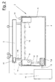
- the test palette (4) is shown in more detail in Figure 2.
- she has the outer shape of the real one in the essential points Production range and preferably has one appropriately designed frame-like frame (6).
- the Test range (4) also has that of the real ones Corresponding mechanical or physical interfaces (14). On the one hand, this is the same suspension (15) or connection to Transport device (5).
- To the interfaces (14) also include a centering device, Guide devices, one preferably non-contact working type recognition for the type of the pallet and the Type of workpiece that may be moved.
- the outer shape and size of the pallets are the same. in the Interacts with the workstation (1) Test range (4) as well as the real production range.
- test palette (4) does not have the final one Tool and workpiece assignment like the real one Production range.
- test pallet (4) no tools and no carried work pieces.
- the test pallet (4) has a simulation device (2) which despite the lack of tools and workpieces Functions of the real production range simulated.
- This Simulation device (2) can with the or the external Controls (10, 11) of the work station (1) or the Transfer line (16) or the station components connected become. This is done via one or more connections (7) on the test pallet (4) for the Equipment supply. Via this connection (7) Control signals, operating currents, compressed air, cooling water, Transfer hydraulics and any other equipment become.
- the pallet-side connector (s) (7) act with corresponding counter connections (8) on the Workstation (1) together and can automatically here when moving the pallet into the work station (1) to be docked.
- the simulation device (2) preferably consists of one or more controls (9), preferably as Sequence controls are designed and the Recreate pallet functions.
- the controls (9) are freely programmable and each have one or more Data and program memory. You can have several Sequence programs for different workpiece types and save different types of production pallets. With A test pallet (4) can thereby different of these Types can be simulated.
- the controls (9) can be constructed constructively in any suitable manner. For example, it is computer-based Controls with one or more microprocessors associated permanent and volatile memories and the associated interfaces for data input and output.
- the controls can also additional Own peripheral units. This can e.g. one or be multiple timers that are hardware or software are trained and the time effects, in particular Delays in the functioning of the real Simulate production range.
- the input devices (12) any external data in a suitable manner to the Control (9) can be reported, e.g. also one Simulation of component detectors is carried out.
- the controls (9) simulate in interaction with the Workstation (1) or the external controls (10,11) different palette functions. This can e.g. the Function of clamping or centering elements on the real one Production range. If the external control (10) the command to open a tensioner to the control (9) transmitted, the controller (9), possibly with a time corresponding to the real function Delay, an enforcement signal back. Alternatively to Testing the wrong routines can also be a failure or Interference signal are reported back. In a similar way can also control the functions of Movement units for handling tools and Workpieces simulated on the real production range become.
- One of the replicable pallet functions is also the sensor technology, which generally measures the processes, Switching, checking and informing includes. About this e.g. Sensor functions for monitoring process flows, e.g.
- Weld quality etc. simulated. are capable of simulation also position reports about the correct insertion position of workpiece parts, taking the working position of Tools etc.
- To simulate pallet functions include the functions of the editing tools the real production range, e.g. the function of Laser welding heads, spot welding guns etc. Simulated can generally be the exchange of signals and information between the different components of the real Production range and the or the external controls (10.11).
- the pallet-side connection (7) is blind switched. This can e.g. Hydraulic or air pressure from the external supply at the workstation (1) queue. Alternatively, a simulating one Consumers on the test pallet (4). Likewise, depending on the equipment, the connections (7) also be open.
Landscapes
- Engineering & Computer Science (AREA)
- Manufacturing & Machinery (AREA)
- General Engineering & Computer Science (AREA)
- Quality & Reliability (AREA)
- Physics & Mathematics (AREA)
- General Physics & Mathematics (AREA)
- Automation & Control Theory (AREA)
- Programmable Controllers (AREA)
- Automatic Assembly (AREA)
Abstract
Description
Anstelle der fertigen Produktionspalette kommt eine abgemagerte Prüfpalette zum Einsatz, die mit einer Simulationseinrichtung zur Nachbildung der Funktionen der echten Produktionspalette ausgerüstet ist. Durch diese Simulationseinrichtung können parallel zur Fahrzeug- und Palettenentwicklung die Komponenten der Arbeitsstation bzw. deren Peripherie und insbesondere die ein oder mehreren zugehörigen Steuerungen eingerichtet und geprüft werden. Insbesondere kann durch die simulierten Palettenfunktionen das Gesamtsystem im Zusammenspiel erprobt werden.
- Figur 1:
- eine Draufsicht auf eine Arbeitsstation mit einer Prüfpalette und
- Figur 2:
- eine vergrößerte Seitenansicht der Prüfpalette.
- 1
- Arbeitsstation
- 2
- Simulationseinrichtung
- 3
- Bearbeitungsvorrichtung, Roboter
- 4
- Prüfpalette
- 5
- Transporteinrichtung
- 6
- Gestell, Rahmen
- 7
- Anschluß Palette
- 8
- Gegenanschluß Arbeitsstation
- 9
- Steuerung Simulationseinrichtung
- 10
- Steuerung extern (Arbeitsstation, Prozeß etc.)
- 11
- Steuerung Transporteinrichtung
- 12
- Eingabevorrichtung
- 13
- Leitung
- 14
- Schnittstelle mechanisch
- 15
- Aufhängung
- 16
- Transferlinie
Claims (8)
- Verfahren zum Prüfen und Einrichten von Arbeitsstationen (1), deren Peripherie und ein oder mehreren zugehörigen Steuerungen (10,11), bei denen ein oder mehrere Paletten mit Werkzeugen und gegebenenfalls mit Werkstücken zugeführt werden, dadurch gekennzeichnet, daß eine Prüfpalette (4) ohne endgültige Werkzeug- und Werkstückbelegung und mit einer Simulationseinrichtung (2) zugeführt wird, die mit der oder den Steuerungen (10,11) an der Arbeitsstation (1) verbunden wird und die die Funktionen der echten Produktionspalette simuliert.
- Vorrichtung zum Prüfen und Einrichten von Arbeitsstationen (1), deren Peripherie und ein oder mehreren zugehörigen Steuerungen (10,11), bei denen ein oder mehrere Paletten mit Werkzeugen und gegebenenfalls mit Werkstücken zugeführt werden, dadurch gekennzeichnet, daß die Vorrichtung eine Prüfpalette (4) ohne endgültige Werkzeug- und Werkstückbelegung und mit einer Simulationseinrichtung (2) aufweist, die mit der oder den Steuerungen (10,11) an der Arbeitsstation (1) verbindbar ist und Funktionen der echten Produktionspalette simuliert.
- Vorrichtung nach Anspruch 2, dadurch gekennzeichnet, daß die Prüfpalette (4) die äußere Form, die mechanischen Schnittstellen (14) und mindestens einen Anschluß (7) für die Betriebsmittel entsprechend der echten Produktionspalette besitzt.
- Vorrichtung nach Anspruch 2 oder 3, dadurch gekennzeichnet, daß die Simulationseinrichtung (2) mindestens eine mit dem Anschluß (7) verbindbare programmierbare Steuerung (9) aufweist.
- Vorrichtung nach Anspruch 2, 3 oder 4, dadurch gekennzeichnet, daß die Steuerung (9) einen Speicher für mehrere Programme und Betriebsdaten von unterschiedlichen Paletten- und Werkstücktypen aufweist.
- Vorrichtung nach einem der Ansprüche 2 bis 5, dadurch gekennzeichnet, daß die Steuerung (9) ein oder mehrere Zeitglieder zur Nachbildung von Zeitfunktionen aufweist.
- Vorrichtung nach einem der Ansprüche 2 bis 6, dadurch gekennzeichnet, daß die Steuerung (9) ein oder mehrere Eingabevorrichtungen (12) zur manuellen oder maschinellen Eingabe von Signalen oder Befehlen aufweist.
- Vorrichtung nach einem der Ansprüche 2 bis 7, dadurch gekennzeichnet, daß die Steuerung (9) als Ablaufsteuerung ausgebildet ist.
Applications Claiming Priority (2)
| Application Number | Priority Date | Filing Date | Title |
|---|---|---|---|
| DE29818337U | 1998-10-16 | ||
| DE29818337U DE29818337U1 (de) | 1998-10-16 | 1998-10-16 | Vorrichtung zum Prüfen und Einrichten von Arbeitsstationen |
Publications (3)
| Publication Number | Publication Date |
|---|---|
| EP0993900A2 true EP0993900A2 (de) | 2000-04-19 |
| EP0993900A3 EP0993900A3 (de) | 2001-11-28 |
| EP0993900B1 EP0993900B1 (de) | 2003-12-17 |
Family
ID=8063902
Family Applications (1)
| Application Number | Title | Priority Date | Filing Date |
|---|---|---|---|
| EP99120425A Expired - Lifetime EP0993900B1 (de) | 1998-10-16 | 1999-10-14 | Vorrichtung zum Prüfen und Einrichten von Arbeitsstationen |
Country Status (2)
| Country | Link |
|---|---|
| EP (1) | EP0993900B1 (de) |
| DE (2) | DE29818337U1 (de) |
Cited By (2)
| Publication number | Priority date | Publication date | Assignee | Title |
|---|---|---|---|---|
| EP1304194A3 (de) * | 2001-10-16 | 2006-02-08 | Fanuc Ltd | Simulationsvorrichtung für einen Roboter |
| EP1770455A3 (de) * | 2005-09-30 | 2008-06-04 | Siemens Aktiengesellschaft | Steuereinrichtung und Datenträger für eine Steuereinrichtung |
Families Citing this family (1)
| Publication number | Priority date | Publication date | Assignee | Title |
|---|---|---|---|---|
| DE10232301B4 (de) * | 2002-07-16 | 2012-01-26 | Robert Bosch Gmbh | Prüfvorrichtung für Komponenten von Einspritzanlagen |
Family Cites Families (10)
| Publication number | Priority date | Publication date | Assignee | Title |
|---|---|---|---|---|
| US4338659A (en) * | 1978-12-15 | 1982-07-06 | Fujitsu Fanuc Ltd. | Position control system for a closed loop type numerical-controlled machine tool |
| DD207778A1 (de) * | 1982-05-19 | 1984-03-14 | Werkzeugind Forschzent | Verfahren und vorrichtung zur anpassung von industrieroboter- und peripheriesteuerungen an werkzeugmaschinensteuerungen |
| SE8305006L (sv) * | 1983-09-19 | 1985-03-20 | David Lindqvist | Forfarande vid linjeproduktion och anordning for genomforande av forfarandet |
| JPH07107647B2 (ja) * | 1988-02-12 | 1995-11-15 | 三菱電機株式会社 | 複数系統制御の干渉チェック方法 |
| DE9102721U1 (de) * | 1991-03-07 | 1991-05-23 | Kuka Schweissanlagen + Roboter Gmbh, 8900 Augsburg | Aufnahmevorrichtung für Werkstücke in einer Transferstraße |
| GB9424707D0 (en) * | 1994-12-07 | 1995-02-01 | Robot Simulations Ltd | Control of industrial robots |
| GB2304649B (en) * | 1995-09-07 | 1999-12-01 | Western Atlas Uk Ltd | Improved gate change facility |
| DE19543826A1 (de) * | 1995-11-23 | 1997-05-28 | Siemens Ag | Simulatoreinheit zum Simulieren einer Peripherieeinheit einer modular aufgebauten speicherprogrammierbaren Steuerung |
| DE19614131A1 (de) * | 1996-04-10 | 1997-10-23 | Agie Ag Ind Elektronik | Verfahren und Vorrichtung zur Steuerung einer Werkzeugmaschine, insbesondere einer Funkenerosionsmaschine |
| DE29712348U1 (de) * | 1997-07-12 | 1998-11-12 | KUKA Schweissanlagen GmbH, 86165 Augsburg | Arbeitsstation in einer Transferlinie |
-
1998
- 1998-10-16 DE DE29818337U patent/DE29818337U1/de not_active Expired - Lifetime
-
1999
- 1999-10-14 EP EP99120425A patent/EP0993900B1/de not_active Expired - Lifetime
- 1999-10-14 DE DE59908084T patent/DE59908084D1/de not_active Expired - Fee Related
Cited By (2)
| Publication number | Priority date | Publication date | Assignee | Title |
|---|---|---|---|---|
| EP1304194A3 (de) * | 2001-10-16 | 2006-02-08 | Fanuc Ltd | Simulationsvorrichtung für einen Roboter |
| EP1770455A3 (de) * | 2005-09-30 | 2008-06-04 | Siemens Aktiengesellschaft | Steuereinrichtung und Datenträger für eine Steuereinrichtung |
Also Published As
| Publication number | Publication date |
|---|---|
| EP0993900B1 (de) | 2003-12-17 |
| EP0993900A3 (de) | 2001-11-28 |
| DE59908084D1 (de) | 2004-01-29 |
| DE29818337U1 (de) | 2000-03-02 |
Similar Documents
| Publication | Publication Date | Title |
|---|---|---|
| DE69815124T2 (de) | Verfahren, anordnung und einrichtung für automontage | |
| DE3221165C2 (de) | ||
| EP0214199B1 (de) | Verfahren und vorrichtung zum automatischen fügen und bearbeiten | |
| DE3715927C2 (de) | ||
| EP1601492A1 (de) | Fertigungsanlage für bauteile, insbesondere karosseriebauteile | |
| DE2928731C2 (de) | Richtpresse | |
| EP1556190A1 (de) | Anlage und verfahren zum bearbeiten von karosserieteilen, wobei roboter mit einem förderband synchronisiert werden | |
| EP1100715A1 (de) | Flexible arbeitsstation und betriebsverfahren | |
| DE102014102990B4 (de) | Fertigungsstation | |
| DE202011000875U1 (de) | Kontrolleinrichtung | |
| DE60219267T2 (de) | Greifeinheit für die automatisierte Bearbeitung von Werkstücken, und Vorrichtung und Verfahren mit einer solchen Einheit | |
| EP0384100A2 (de) | Kraftbetriebener zangenartiger Werkzeugträger für Handhabungsgeräte | |
| DE102018114867A1 (de) | Verfahren zum Verbinden von Bauteilen | |
| DE60121941T2 (de) | Herstellungsverfahren und herstellungsanlage | |
| EP0993900B1 (de) | Vorrichtung zum Prüfen und Einrichten von Arbeitsstationen | |
| DE10234321B3 (de) | Vorrichtung und Verfahren zum Spannen von Werkstücken | |
| EP3344417B1 (de) | Fertigungsmodul und verfahren zum betreiben des fertigungsmoduls | |
| DE3621604C2 (de) | ||
| EP0743135A2 (de) | Verfahren zum Verbinden von zwei Werkstücken | |
| DE102017005882B4 (de) | Verfahren zum Betrieb eines Roboters zur Überprüfung seiner Arbeitsumgebung | |
| DE19834702A1 (de) | Nietvorrichtung zum Herstellen eines tonnenförmigen Bauteils, vorzugsweise eines Flugzeugrumpfes | |
| DE3536015C2 (de) | Fertigungsstation für unterschiedliche Typen von Kraftfahrzeug-Karosserien | |
| DE2601823A1 (de) | Verfahren zur steuerung einer taktweisen fliessfertigung | |
| DE3341294C2 (de) | ||
| EP3795344B1 (de) | Presslinie und verfahren der kontrolle der gepressten teile auf dieser linie |
Legal Events
| Date | Code | Title | Description |
|---|---|---|---|
| PUAI | Public reference made under article 153(3) epc to a published international application that has entered the european phase |
Free format text: ORIGINAL CODE: 0009012 |
|
| AK | Designated contracting states |
Kind code of ref document: A2 Designated state(s): AT BE CH CY DE DK ES FI FR GB GR IE IT LI LU MC NL PT SE Kind code of ref document: A2 Designated state(s): BE DE SE |
|
| AX | Request for extension of the european patent |
Free format text: AL;LT;LV;MK;RO;SI |
|
| PUAL | Search report despatched |
Free format text: ORIGINAL CODE: 0009013 |
|
| AK | Designated contracting states |
Kind code of ref document: A3 Designated state(s): AT BE CH CY DE DK ES FI FR GB GR IE IT LI LU MC NL PT SE |
|
| AX | Request for extension of the european patent |
Free format text: AL;LT;LV;MK;RO;SI |
|
| 17P | Request for examination filed |
Effective date: 20020503 |
|
| AKX | Designation fees paid |
Free format text: BE DE SE |
|
| GRAP | Despatch of communication of intention to grant a patent |
Free format text: ORIGINAL CODE: EPIDOSNIGR1 |
|
| GRAS | Grant fee paid |
Free format text: ORIGINAL CODE: EPIDOSNIGR3 |
|
| GRAA | (expected) grant |
Free format text: ORIGINAL CODE: 0009210 |
|
| AK | Designated contracting states |
Kind code of ref document: B1 Designated state(s): BE DE SE |
|
| REG | Reference to a national code |
Ref country code: SE Ref legal event code: TRGR |
|
| REF | Corresponds to: |
Ref document number: 59908084 Country of ref document: DE Date of ref document: 20040129 Kind code of ref document: P |
|
| PLBE | No opposition filed within time limit |
Free format text: ORIGINAL CODE: 0009261 |
|
| STAA | Information on the status of an ep patent application or granted ep patent |
Free format text: STATUS: NO OPPOSITION FILED WITHIN TIME LIMIT |
|
| 26N | No opposition filed |
Effective date: 20040920 |
|
| PGFP | Annual fee paid to national office [announced via postgrant information from national office to epo] |
Ref country code: DE Payment date: 20050915 Year of fee payment: 7 |
|
| PGFP | Annual fee paid to national office [announced via postgrant information from national office to epo] |
Ref country code: SE Payment date: 20051024 Year of fee payment: 7 Ref country code: BE Payment date: 20051024 Year of fee payment: 7 |
|
| PG25 | Lapsed in a contracting state [announced via postgrant information from national office to epo] |
Ref country code: SE Free format text: LAPSE BECAUSE OF NON-PAYMENT OF DUE FEES Effective date: 20061015 |
|
| PG25 | Lapsed in a contracting state [announced via postgrant information from national office to epo] |
Ref country code: DE Free format text: LAPSE BECAUSE OF NON-PAYMENT OF DUE FEES Effective date: 20070501 |
|
| EUG | Se: european patent has lapsed | ||
| BERE | Be: lapsed |
Owner name: *KUKA SCHWEISSANLAGEN G.M.B.H. Effective date: 20061031 |
|
| PG25 | Lapsed in a contracting state [announced via postgrant information from national office to epo] |
Ref country code: BE Free format text: LAPSE BECAUSE OF FAILURE TO SUBMIT A TRANSLATION OF THE DESCRIPTION OR TO PAY THE FEE WITHIN THE PRESCRIBED TIME-LIMIT Effective date: 20061031 |