EP0993924A1 - Vorrichtung zur Herstellung von Vorformlingen in Fertigungsanlagen zur Herstellung von Flaschen und Behältern oder Produkten unterschiedlicher Art - Google Patents
Vorrichtung zur Herstellung von Vorformlingen in Fertigungsanlagen zur Herstellung von Flaschen und Behältern oder Produkten unterschiedlicher Art Download PDFInfo
- Publication number
- EP0993924A1 EP0993924A1 EP99119815A EP99119815A EP0993924A1 EP 0993924 A1 EP0993924 A1 EP 0993924A1 EP 99119815 A EP99119815 A EP 99119815A EP 99119815 A EP99119815 A EP 99119815A EP 0993924 A1 EP0993924 A1 EP 0993924A1
- Authority
- EP
- European Patent Office
- Prior art keywords
- moulding
- preforms
- preform
- containers
- mould
- Prior art date
- Legal status (The legal status is an assumption and is not a legal conclusion. Google has not performed a legal analysis and makes no representation as to the accuracy of the status listed.)
- Granted
Links
- 238000004519 manufacturing process Methods 0.000 title claims abstract description 33
- 238000002360 preparation method Methods 0.000 title claims abstract description 27
- 238000000465 moulding Methods 0.000 claims abstract description 55
- 239000004033 plastic Substances 0.000 claims abstract description 12
- 239000000463 material Substances 0.000 claims abstract description 10
- 238000001816 cooling Methods 0.000 claims abstract description 8
- 230000008878 coupling Effects 0.000 claims abstract description 6
- 238000010168 coupling process Methods 0.000 claims abstract description 6
- 238000005859 coupling reaction Methods 0.000 claims abstract description 6
- 238000012545 processing Methods 0.000 claims abstract description 3
- 239000002184 metal Substances 0.000 claims description 3
- 238000000071 blow moulding Methods 0.000 description 9
- 238000002347 injection Methods 0.000 description 7
- 239000007924 injection Substances 0.000 description 7
- 230000003750 conditioning effect Effects 0.000 description 3
- 230000007246 mechanism Effects 0.000 description 3
- 238000002844 melting Methods 0.000 description 3
- 230000008018 melting Effects 0.000 description 3
- 239000012815 thermoplastic material Substances 0.000 description 3
- 238000012546 transfer Methods 0.000 description 3
- 238000000034 method Methods 0.000 description 2
- 230000006641 stabilisation Effects 0.000 description 2
- 238000011105 stabilization Methods 0.000 description 2
- 238000004891 communication Methods 0.000 description 1
- 238000010276 construction Methods 0.000 description 1
- 238000003780 insertion Methods 0.000 description 1
- 230000037431 insertion Effects 0.000 description 1
- 230000002452 interceptive effect Effects 0.000 description 1
- 238000004806 packaging method and process Methods 0.000 description 1
- 230000001360 synchronised effect Effects 0.000 description 1
Images


Classifications
-
- B—PERFORMING OPERATIONS; TRANSPORTING
- B29—WORKING OF PLASTICS; WORKING OF SUBSTANCES IN A PLASTIC STATE IN GENERAL
- B29C—SHAPING OR JOINING OF PLASTICS; SHAPING OF MATERIAL IN A PLASTIC STATE, NOT OTHERWISE PROVIDED FOR; AFTER-TREATMENT OF THE SHAPED PRODUCTS, e.g. REPAIRING
- B29C45/00—Injection moulding, i.e. forcing the required volume of moulding material through a nozzle into a closed mould; Apparatus therefor
- B29C45/03—Injection moulding apparatus
- B29C45/04—Injection moulding apparatus using movable moulds or mould halves
- B29C45/0408—Injection moulding apparatus using movable moulds or mould halves involving at least a linear movement
- B29C45/0416—Injection moulding apparatus using movable moulds or mould halves involving at least a linear movement co-operating with fixed mould halves
-
- B—PERFORMING OPERATIONS; TRANSPORTING
- B29—WORKING OF PLASTICS; WORKING OF SUBSTANCES IN A PLASTIC STATE IN GENERAL
- B29C—SHAPING OR JOINING OF PLASTICS; SHAPING OF MATERIAL IN A PLASTIC STATE, NOT OTHERWISE PROVIDED FOR; AFTER-TREATMENT OF THE SHAPED PRODUCTS, e.g. REPAIRING
- B29C45/00—Injection moulding, i.e. forcing the required volume of moulding material through a nozzle into a closed mould; Apparatus therefor
- B29C45/17—Component parts, details or accessories; Auxiliary operations
- B29C45/26—Moulds
- B29C45/32—Moulds having several axially spaced mould cavities, i.e. for making several separated articles
-
- B—PERFORMING OPERATIONS; TRANSPORTING
- B29—WORKING OF PLASTICS; WORKING OF SUBSTANCES IN A PLASTIC STATE IN GENERAL
- B29C—SHAPING OR JOINING OF PLASTICS; SHAPING OF MATERIAL IN A PLASTIC STATE, NOT OTHERWISE PROVIDED FOR; AFTER-TREATMENT OF THE SHAPED PRODUCTS, e.g. REPAIRING
- B29C45/00—Injection moulding, i.e. forcing the required volume of moulding material through a nozzle into a closed mould; Apparatus therefor
- B29C45/17—Component parts, details or accessories; Auxiliary operations
- B29C45/72—Heating or cooling
- B29C45/7207—Heating or cooling of the moulded articles
-
- B—PERFORMING OPERATIONS; TRANSPORTING
- B29—WORKING OF PLASTICS; WORKING OF SUBSTANCES IN A PLASTIC STATE IN GENERAL
- B29K—INDEXING SCHEME ASSOCIATED WITH SUBCLASSES B29B, B29C OR B29D, RELATING TO MOULDING MATERIALS OR TO MATERIALS FOR MOULDS, REINFORCEMENTS, FILLERS OR PREFORMED PARTS, e.g. INSERTS
- B29K2105/00—Condition, form or state of moulded material or of the material to be shaped
- B29K2105/25—Solid
- B29K2105/253—Preform
Definitions
- the invention refers to an apparatus for the preparation of preforms to be used in manufacturing plants provided for the production of bottles and containers or products of various kind, such an apparatus being adapted to prepare the preforms in a manner that is not only quick, but also different from the traditional one, in view of the subsequent utilization of said preforms for the production of said products therefrom.
- Plants for producing bottles and containers of various kind through the use of plastic materials such as PET, PEN and thermoplastic materials of various kind are generally known in the art to substantially comprise a preform forming station that is formed by at least a machine tool such as for instance a screw extruder, into which the plastic material is fed in pelletized form for being first heated up to its melting temperature, or melt point, and then injected by means of moulding presses through injection conduits communicating with moulds formed by a group of cavities and a group of plungers, or punches, thereby filling the various cavities of each such mould in view of in this manner forming respective preforms to be eventually used for the production of the above cited containers or bottles.
- a machine tool such as for instance a screw extruder
- These plants further comprise stations in which the so moulded preforms are sequentially allowed to cool down to temperature values below the melting temperature of the respectively used thermoplastic materials, are allowed to stabilize at the respectively reached temperature, and are finally subjected to a blow moulding process, in which moulding tools and equipment of a traditional type are generally used, in view of thereby producing the bottles or containers to the desired shape and size, wherein said bottles or containers are finally ejected from the plant in a traditional manner and packaged for shipment to the customers.
- the moulds that are currently used in the above cited preform forming phase are displaced, during the moulding phase, in that the group of plungers or punches, which are generally movable, are caused to move against the group of cavities, which are generally of the stationary type, during the mould clamping phase, whereas, at the end of the moulding cycle, said group of plungers or punches are temporarily moved away from said group of cavities in order to enable the so formed preforms to be removed from said group of cavities and undergo the subsequent cool-down and temperature stabilization phases preceding the final blow moulding of the same preforms into the final products, ie. bottles or containers of various kind, after which the above cited groups of plungers or punches and cavities of the preform forming moulds are again moved against each other for a new preform forming cycle.
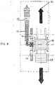
- FIG. 10 The above listed Figures are shown to schematically illustrate a preform preparation apparatus, which is generally indicated at 10, as used either in combination or not with manufacturing plants of the so-called single-stage or two-stage type for the production of plastic bottles or containers of various kind, to the purpose of preparing such preforms that are subsequently processed andconverted into bottles or containers in said manufacturing plants.
- Figures 1 and 2 can be noticed to schematically illustrate two manufacturing plants of the single-stage type for the production of bottles of various kind by using plastic materials such as PET and PEN and thermoplastic materials of various kind, in which each such plant is shown to essentially comprise a moulding station 11 for the preparation of the preforms, which is provided with the features that will be more exhaustively described in the following description, and a series of subsequent stations for cooling down said preforms to pre-determined temperatures and conditioning them at said temperatures, as well as eventually blow moulding said preforms in view of producing said bottles or containers to the required or desired shapes and sizes, under subsequent ejection of the so produced bottles or containers from the plant and packaging of said products for final shipping to the customers.
- plastic materials such as PET and PEN and thermoplastic materials of various kind
- Figure 1 can be noticed to illustrate a first type of a traditional plant for the production of bottles or containers, in which the moulding station 11 is constituted by at least a machine tool such as for instance a screw extruder 12, into which the materials used in the production of the preforms is fed in the form of pelletized plastic material.
- a plastic material is then gradually heated up and fed forwards along the inner pastication or melting chamber 13 of the extruder, thereby obtaining a mass of mixed molten plastic that is then conveyed through a traditional injection channel 14 communicating with the extruder 12, from which it is then injected into the preform preparation apparatus 15 according to the present invention which is arranged close to and in communication with said injection channel 14 and is made with the features that will be more exhaustively described further on.
- the bottle production plant being considered here is further provided with at least two separate production lines 16 and 17 arranged close to each other in a mutually parallel arrangement, each one of which is formed by at least a loading unit 18 of a traditional type arranged in a position that is quite close to the preform preparation apparatus 15, on which the preforms prepared with the above cited preform preparation apparatus are loaded, and which provides for said preforms to be then transferred onto a conveyor (not shown) that carries them in a sequence through traditional preform cooling-down and preform conditioning stations 19, temperature stabilization stations 20 and blow moulding stations 21, in which corresponding bottles or containers are obtained from said preforms, until a final ejection station is reached where the so obtained bottles or containers are eventually unloaded from the plant.
- such a preform preparation apparatus is essentially constituted by at least a main moulding tool formed by a mould 22 containing the various cavities for the preparation of the preforms from which said bottles or containers have then to be obtained, said mould being arranged and appropriately fastened on a side of the injection channel 14 so that the injection nozzle 23 of the latter is in a coinciding arrangement with at least an injection gate or runner 24 of the same mould, which is in turn communicating with the various moulding cavities 25 of said main mould.
- the preform preparation apparatus is further constituted by at least a pair of moving moulds 26 and 27, which are similar to each other, are provided with plungers or punches 28 facing the corresponding cavities 25 of the main mould 22, and are adapted to compliably fit into said cavities so as to thereby define the cavities that can be filled with molten plastic material for the preparation of the preforms intended to be then blow moulded into bottles or containers.
- Such moving moulds 26 and 27 are in an advantageous manner applied in a position above the main mould 22 and are driven by therewith associated guiding and handling mechanisms of a per se known type (not shown in the Figures) so as to enable them to be displaced separately with respect to the main mould with two different movements, ie.
- the main mould 22, in which said preforms are so moulded is brought selectively into contact with either one or the other of the so provided moving moulds or, if required, even with further moving moulds that may possibly be mutually associated according to the same principles and criteria as described above, so that while preforms are so moulded in a moulding cycle being performed in the mutually coupled moulds, the other moving mould, with the previously moulded preforms still coupled to the related plungers or punches, is actually exposed to the atmosphere, so that these preforms can be removed therefrom and transferred to the loading unit 18 of the therewith associated production line in view of being subsequently allowed to undergo the necessary cool-down, conditioning and final blow moulding phases for forming the corresponding final products in the form of bottles or containers.
- the removal of the preforms from the respective moving mould is carried out by means of appropriate tools of a traditional type in a relatively short time so as to clear said mould and make it ready to be brought again into coupling with the main mould for moulding further preforms with cycle times that are extremely short, so that the operational sequence of the apparatus according to the present invention actually enables the amount of pieces moulded in a same period of working time to be significantly increased with respect to the currently used moulding equipment and tools.
- the moving moulds can of course can be mounted, further to said vertical superposed position that has been illustrated by way of example in the above description, also in different positions, such as for example in a horizontal or an inclined position with respect to the main mould, provided that each one of said moulds are anyway able to couple with said main mould in view of moulding the preforms, without thereby departing from the scope of the present invention.
- FIGS 3 to 6 illustrate the various working positions into which the apparatus according to the present invention is brought throughout a preform moulding cycle, and in which the moving moulds 26 and 27 can be noticed to be provided on top with appropriately designed, common-use guiding and handling mechanisms 29 that enable them to be contemporaneously displaced along the longitudinal direction A from one to the other one of their working positions, when both of them are in their raised position, and that on the other hand also enable only the moving mould that is from time to time positioned in coincidence with the main mould 22 therebelow to be displaced along the direction D from one position thereof to the other one, while the other moving mould is in this case always maintained motionless in its raised position non-coinciding with said main mould.
- Figure 3 can be noticed to illustrate the mould assembly that is displaced in the position in which the first moving mould 26 is arranged so as to enable the related preform moulding cycle to be carried out, while the second moving mould 27 is still carries the previously moulded preforms associated therewith.
- said first moving mould turns out to be positioned in correspondence of the main mould 22, and is lowered and coupled with said main mould, thereby enabling the related preforms to be moulded within said moulds, while the second moving mould 27 remains in turn raised in a position position that is laterally displaced with respect to and non-coinciding with said main mould, in which said plungers or punches 28 along with the related, still therewith coupled preforms 30 are exposed to the atmosphere under resulting cool-down of all said preforms.
- the loading unit 18 (not indicated) of the associated production line of the plant is raised in the direction G, so that its cavities (not indicated), provided to accomodate said preforms, are brought into coincidence and are therefore able to couple with all said prepared preforms 30 and the related plungers or punches 28, in order to then remove all such preforms therefrom and transfer them into said cavities of said loading unit.
- the latter are either inserted into appropriate cooled metal containers 31 provided in the loaded unit 18 and sized so as to be able to removably accomodate the same preforms, and provided with large surfaces in order to be able to effectively dissipate the heat from the preforms and thereby reduce the temperature thereof, or may also be associated to cooling means of various kind and conformation in view of obtaining the same results.
- the first moving mould 26 is raised at the end of the moulding of the related preforms, while the same preforms remain therefore coupled, ie. attached to the corresponding plungers or punches 28, thereby moving back to the same level as the second moving mould 27 that has in the meanwhile dwelled in the same position it had before.
- the loading unit 18 is in turn lowered along the direction H under resulting release of the preforms 30 from said moving mould and insertion thereof in the cooled containers 31 which are housed in the cavities of the same loading unit.
- both moving moulds 26 and 27 have been displaced at the same time along the longitudinal direction A, in the direction B, so as to move the first moving mould 26 into a raised position non-coinciding with the main mould 22, and the second moving mould 27 into a raised position coinciding with the main mould 22 therebelow.
- the first moving mould 26 remains in the above cited operational position and the loading unit therebelow (not indicated), whose cooled containers 31 are arranged in a position coinciding with the corresponding plungers or punches 28 and the thereto attached preforms, is raised so as to enable the same preforms to be accomodated in said cooled containers, after which all preforms will then be released from the same containers and transferred on to said loading unit.
- the second moving mould 27 is raised at the end of the moulding of the related preforms, and that such preforms remain therefore attached to the corresponding plungers or punches 28, thereby moving back to the same level as the first moving mould 26 that has in the meanwhile dwelled in the same position it had before; at the same time the loading unit 18 is in turn lowered in the direction H under resulting release of the preforms from said moving mould and transfer thereof onto the same loading unit, while both moving moulds get arranged for a next preform moulding cycle in that both said moving moulds are contemporaneously displaced along the longitudinal direction A, and in the direction C opposite to the previously cited one, after which all of the afore described operational sequences are then repeated.
- the preform preparation apparatus actually enables the production capacity of the plants for producing bottles or containers of various kind to be significantly increased, while making use of normally sized moulds having the same number of moulding cavities as the currently used moulds, by minimizing downtimes owing to the preforms being able to be moulded alternately with either one of the moving moulds 26 and 27 and the cooling phase of the same preforms being able to be started as soon as such preforms have been moulded, ie. almost as further preforms are being moulded, thereby making it possible for extremely short cycle times to be obtained.
- this apparatus can be used not only in connection with plants for moulding bottles or containers of the above cited kind, but also for producing any other kind of products, even with methods differing from the blow moulding technique, either in combination or not with appropriate plants for manufacturing the same products, without departing from the scope of the present invention.
- FIG. 2 it can be noticed to illustrate a further plant that is traditionally used to produce bottles or containers, and that substantially comprises a moulding station 11 similar to the afore described one, and two production lines 16 and 17 converging in a loading station 32 that communicates with a rotary (ie. carrousel-type) blow moulding station 33.
- the preforms being moulded in the moulding station 11 are released from the related moving moulds in the same station and selectively transferred by means of corresponding loading units (not shown) along the production lines, from which they are conveyed first to the loading station 32 and, then, from the latter selectively to the rotary blow moulding station 33, while the bottles or containers produced in said blow moulding station are finally ejected from the production plant and packaged for shipping to the customers.
- FIG. 7 can now be seen to illustrate the preform preparation apparatus according to the present invention in a second embodiment thereof, in which it can be noticed that said apparatus is again formed by a single main mould 22 which, however, is adapted to perform moulding operations also in combination with a further pair of moving moulds 26 and 27 so as to further increase the production capacity of the associated plant for producing bottles or containers.
- the main mould 22 is shaped so as to feature two mutually separated series of moulding cavities 25, that are preferably also arranged in mutually opposing positions, so as to favour the moulding operations of the related preforms and preventing each such series of cavities from possibly interfering with the plungers or punches cooperating with the other series of moulding cavities, while said further pair of moving moulds 26 and 27 are in turn arranged in a position opposing the additional series of moulding cavities 25 and symmetrical with respect to the one of the afore described moving moulds, and are in turn associated with guyiding and handling mechanisms that are similar to the afore described ones and are therefore able to determine a similar operation thereof.
- each loading unit 18 is provided to include further preform accomodating cavities facing the plungers or punches 28 of said further moving moulds, in which there are inserted corresponding cooled containers 31 performing the same task as described above.
- FIG. 8 can now be seen to illustrate the preform preparation apparatus according to the present invention in a third embodiment thereof, in which it can be noticed that such an apparatus is constituted solely by theabove described moulding station 11 that is no longer combined with manufacturing plants of the afore described single-stage type, thereby forming an autonomous manufacturing plant of the two-stage type enabling preforms of bottles or containers or products of any other kind to be produced separately, to be then cooled down within corresponding cooled containers 31 inserted on to them, in view of subsequently processing the same preforms in separate machines or plants after the removal thereof from said containers, so as to obtain the desired or required finished products.
Landscapes
- Engineering & Computer Science (AREA)
- Manufacturing & Machinery (AREA)
- Mechanical Engineering (AREA)
- Blow-Moulding Or Thermoforming Of Plastics Or The Like (AREA)
- Processing And Handling Of Plastics And Other Materials For Molding In General (AREA)
- Moulds For Moulding Plastics Or The Like (AREA)
- Mushroom Cultivation (AREA)
Applications Claiming Priority (2)
| Application Number | Priority Date | Filing Date | Title |
|---|---|---|---|
| ITTV980137 | 1998-10-13 | ||
| IT1998TV000137A IT1303365B1 (it) | 1998-10-13 | 1998-10-13 | Dispositivo di preparazione di preforme per impianti di fabbricazionedi bottiglie e contenitori o prodotti di vario genere. |
Publications (2)
| Publication Number | Publication Date |
|---|---|
| EP0993924A1 true EP0993924A1 (de) | 2000-04-19 |
| EP0993924B1 EP0993924B1 (de) | 2003-02-12 |
Family
ID=11420492
Family Applications (1)
| Application Number | Title | Priority Date | Filing Date |
|---|---|---|---|
| EP99119815A Expired - Lifetime EP0993924B1 (de) | 1998-10-13 | 1999-10-06 | Vorrichtung zur Herstellung von Vorformlingen in Fertigungsanlagen zur Herstellung von Flaschen und Behältern oder Produkten unterschiedlicher Art |
Country Status (6)
| Country | Link |
|---|---|
| US (1) | US6428304B1 (de) |
| EP (1) | EP0993924B1 (de) |
| AT (1) | ATE232444T1 (de) |
| CA (1) | CA2285772A1 (de) |
| DE (1) | DE69905323T2 (de) |
| IT (1) | IT1303365B1 (de) |
Families Citing this family (7)
| Publication number | Priority date | Publication date | Assignee | Title |
|---|---|---|---|---|
| US6652262B2 (en) * | 2001-07-24 | 2003-11-25 | Caco Pacific Corporation | Injection mold apparatus with improved take-off plate |
| US7946836B2 (en) * | 2008-05-23 | 2011-05-24 | Roberto Sicilia | Injection molding and temperature conditioning apparatus |
| US9067254B2 (en) * | 2008-10-16 | 2015-06-30 | The Coca-Cola Company | Method of configuring a production line to mass customize shaped vessels |
| ITBO20110691A1 (it) | 2011-12-02 | 2013-06-03 | Ativa | Linea e procedimento di imbottigliamento in ciclo continuo di contenitori in materiale termoplastico. |
| DE102016103756A1 (de) * | 2016-03-02 | 2017-09-07 | Krones Ag | Anlage und Verfahren zum Behandeln von Kunststoffvorformlingen mit Luftförderer oder Transportshuttle |
| EP4209323A1 (de) * | 2018-08-30 | 2023-07-12 | Husky Injection Molding Systems Luxembourg IP Development S.à.r.l | Kunststoffformvorrichtung mit formermodul |
| US12325164B2 (en) | 2019-06-25 | 2025-06-10 | Husky Injection Molding Systems Ltd. | Molding apparatus and methods |
Citations (7)
| Publication number | Priority date | Publication date | Assignee | Title |
|---|---|---|---|---|
| FR2391059A1 (fr) * | 1977-05-21 | 1978-12-15 | Linde Ag | Procede et installation de moulage par injection |
| EP0058947A1 (de) * | 1981-02-23 | 1982-09-01 | The Continental Group, Inc. | Verfahren und Vorrichtung zum Formen von Flaschenvorformlingen |
| US4472131A (en) * | 1979-12-03 | 1984-09-18 | Ryder Leonard B | Apparatus for injection molding of plastic preform |
| US4836767A (en) * | 1987-11-25 | 1989-06-06 | Husky Injection Molding System, Ltd. | Swing plate molding machine |
| EP0688651A1 (de) * | 1994-06-20 | 1995-12-27 | Inter Tooling Services B.V. | Spritzgiessmaschine und Verfahren zur Herstellung von Hohlkörpern aus Kunststoff |
| DE19621203A1 (de) * | 1996-05-25 | 1997-03-20 | Krupp Ag Hoesch Krupp | Verfahren zum Spritzgießen von Spritzlingen und Vorrichtung für die Durchführung des Verfahrens |
| US5662945A (en) * | 1995-02-15 | 1997-09-02 | Owens-Brockway Plastic Products Inc. | Injection blow molding machine with stacked molds |
Family Cites Families (8)
| Publication number | Priority date | Publication date | Assignee | Title |
|---|---|---|---|---|
| IT1016715B (it) * | 1973-08-01 | 1977-06-20 | Unilever Nv | Apparecchio per lo stampaggio ad iniezione di articoli cavi di ma teria plastica |
| US4197073A (en) * | 1978-05-10 | 1980-04-08 | Husky Injection Molding Systems Limited | Combined injection-molding and blow-molding plant |
| US4604258A (en) * | 1984-11-15 | 1986-08-05 | Canada Cup, Inc. | Stack-mold for injection blow molding |
| US5051227A (en) * | 1988-12-05 | 1991-09-24 | Electra Form, Inc. | Production of preforms and blow molded articles |
| US5589130A (en) * | 1993-07-30 | 1996-12-31 | Nissei Asb Machine Co., Ltd. | Method of injection molding a preform and apparatus for the same |
| US5501593A (en) * | 1994-04-07 | 1996-03-26 | Marcus; Paul | Parison molding apparatus |
| JP3816537B2 (ja) * | 1996-09-02 | 2006-08-30 | 日精エー・エス・ビー機械株式会社 | 射出ブロー成形装置、射出ブロー成形方法及び射出成形装置 |
| NL1005872C2 (nl) * | 1997-04-22 | 1998-10-29 | Inter Tooling Services Bv | Spuitgietmachine voor het spuitgieten van preforms voor kunststof flessen en soortgelijke houders. |
-
1998
- 1998-10-13 IT IT1998TV000137A patent/IT1303365B1/it active IP Right Grant
-
1999
- 1999-10-06 DE DE69905323T patent/DE69905323T2/de not_active Expired - Fee Related
- 1999-10-06 EP EP99119815A patent/EP0993924B1/de not_active Expired - Lifetime
- 1999-10-06 AT AT99119815T patent/ATE232444T1/de not_active IP Right Cessation
- 1999-10-08 CA CA002285772A patent/CA2285772A1/en not_active Abandoned
- 1999-10-08 US US09/416,211 patent/US6428304B1/en not_active Expired - Fee Related
Patent Citations (7)
| Publication number | Priority date | Publication date | Assignee | Title |
|---|---|---|---|---|
| FR2391059A1 (fr) * | 1977-05-21 | 1978-12-15 | Linde Ag | Procede et installation de moulage par injection |
| US4472131A (en) * | 1979-12-03 | 1984-09-18 | Ryder Leonard B | Apparatus for injection molding of plastic preform |
| EP0058947A1 (de) * | 1981-02-23 | 1982-09-01 | The Continental Group, Inc. | Verfahren und Vorrichtung zum Formen von Flaschenvorformlingen |
| US4836767A (en) * | 1987-11-25 | 1989-06-06 | Husky Injection Molding System, Ltd. | Swing plate molding machine |
| EP0688651A1 (de) * | 1994-06-20 | 1995-12-27 | Inter Tooling Services B.V. | Spritzgiessmaschine und Verfahren zur Herstellung von Hohlkörpern aus Kunststoff |
| US5662945A (en) * | 1995-02-15 | 1997-09-02 | Owens-Brockway Plastic Products Inc. | Injection blow molding machine with stacked molds |
| DE19621203A1 (de) * | 1996-05-25 | 1997-03-20 | Krupp Ag Hoesch Krupp | Verfahren zum Spritzgießen von Spritzlingen und Vorrichtung für die Durchführung des Verfahrens |
Also Published As
| Publication number | Publication date |
|---|---|
| CA2285772A1 (en) | 2000-04-13 |
| DE69905323D1 (de) | 2003-03-20 |
| IT1303365B1 (it) | 2000-11-06 |
| ATE232444T1 (de) | 2003-02-15 |
| US6428304B1 (en) | 2002-08-06 |
| ITTV980137A1 (it) | 2000-04-13 |
| DE69905323T2 (de) | 2003-06-18 |
| EP0993924B1 (de) | 2003-02-12 |
Similar Documents
| Publication | Publication Date | Title |
|---|---|---|
| JP7149373B2 (ja) | 成形装置および方法 | |
| EP0283644B2 (de) | Vorrichtung zum Herstellen von hohlen Artikeln aus Kunststoff | |
| USRE33237E (en) | Apparatus for producing hollow plastic articles | |
| US4313905A (en) | Blow molding method | |
| CA2154343C (en) | Method and apparatus for manufacturing hollow objects, in particular plastic preforms | |
| US6428304B1 (en) | Apparatus for the preparation of preforms in manufacturing plants for the production of bottles and containers or products of various kind | |
| CN101132901A (zh) | 具有高生产效率和低系统成本的注射成型系统 | |
| US3192569A (en) | Apparatus for molding articles of plastic | |
| EP3278952B1 (de) | Behälterherstellungsvorrichtung | |
| US20010038866A1 (en) | Machine for the production of preforms for hollow plastic containers | |
| EP1272327B1 (de) | Spritzgiessmaschine für kunststoffbehälter mit schnellformwechseleinrichtung | |
| US3999915A (en) | Liner feeder apparatus | |
| EP0688651A1 (de) | Spritzgiessmaschine und Verfahren zur Herstellung von Hohlkörpern aus Kunststoff | |
| US4230298A (en) | Apparatus for the preparation of hollow plastic articles | |
| US4225304A (en) | Apparatus for the preparation of hollow plastic articles | |
| CN104191550B (zh) | 塑料容器的制造装置及方法 | |
| CN224044493U (zh) | 制造机器和分离设备 | |
| WO2004078444A2 (en) | Process and mold for plastic pack molding | |
| JPH05111927A (ja) | 樹脂モールド装置 | |
| JPS6140531B2 (de) |
Legal Events
| Date | Code | Title | Description |
|---|---|---|---|
| PUAI | Public reference made under article 153(3) epc to a published international application that has entered the european phase |
Free format text: ORIGINAL CODE: 0009012 |
|
| AK | Designated contracting states |
Kind code of ref document: A1 Designated state(s): AT BE CH CY DE DK ES FI FR GB GR IE IT LI LU MC NL PT SE |
|
| AX | Request for extension of the european patent |
Free format text: AL;LT;LV;MK;RO;SI |
|
| 17P | Request for examination filed |
Effective date: 20001010 |
|
| AKX | Designation fees paid |
Free format text: AT BE CH CY DE DK ES FI FR GB GR IE IT LI LU MC NL PT SE |
|
| 17Q | First examination report despatched |
Effective date: 20010521 |
|
| GRAG | Despatch of communication of intention to grant |
Free format text: ORIGINAL CODE: EPIDOS AGRA |
|
| GRAG | Despatch of communication of intention to grant |
Free format text: ORIGINAL CODE: EPIDOS AGRA |
|
| GRAH | Despatch of communication of intention to grant a patent |
Free format text: ORIGINAL CODE: EPIDOS IGRA |
|
| GRAH | Despatch of communication of intention to grant a patent |
Free format text: ORIGINAL CODE: EPIDOS IGRA |
|
| GRAA | (expected) grant |
Free format text: ORIGINAL CODE: 0009210 |
|
| AK | Designated contracting states |
Designated state(s): AT BE CH CY DE DK ES FI FR GB GR IE IT LI LU MC NL PT SE |
|
| PG25 | Lapsed in a contracting state [announced via postgrant information from national office to epo] |
Ref country code: NL Free format text: LAPSE BECAUSE OF FAILURE TO SUBMIT A TRANSLATION OF THE DESCRIPTION OR TO PAY THE FEE WITHIN THE PRESCRIBED TIME-LIMIT Effective date: 20030212 Ref country code: LI Free format text: LAPSE BECAUSE OF FAILURE TO SUBMIT A TRANSLATION OF THE DESCRIPTION OR TO PAY THE FEE WITHIN THE PRESCRIBED TIME-LIMIT Effective date: 20030212 Ref country code: IT Free format text: LAPSE BECAUSE OF FAILURE TO SUBMIT A TRANSLATION OF THE DESCRIPTION OR TO PAY THE FEE WITHIN THE PRESCRIBED TIME-LIMIT;WARNING: LAPSES OF ITALIAN PATENTS WITH EFFECTIVE DATE BEFORE 2007 MAY HAVE OCCURRED AT ANY TIME BEFORE 2007. THE CORRECT EFFECTIVE DATE MAY BE DIFFERENT FROM THE ONE RECORDED. Effective date: 20030212 Ref country code: GR Free format text: LAPSE BECAUSE OF FAILURE TO SUBMIT A TRANSLATION OF THE DESCRIPTION OR TO PAY THE FEE WITHIN THE PRESCRIBED TIME-LIMIT Effective date: 20030212 Ref country code: FR Free format text: LAPSE BECAUSE OF FAILURE TO SUBMIT A TRANSLATION OF THE DESCRIPTION OR TO PAY THE FEE WITHIN THE PRESCRIBED TIME-LIMIT Effective date: 20030212 Ref country code: FI Free format text: LAPSE BECAUSE OF FAILURE TO SUBMIT A TRANSLATION OF THE DESCRIPTION OR TO PAY THE FEE WITHIN THE PRESCRIBED TIME-LIMIT Effective date: 20030212 Ref country code: CH Free format text: LAPSE BECAUSE OF FAILURE TO SUBMIT A TRANSLATION OF THE DESCRIPTION OR TO PAY THE FEE WITHIN THE PRESCRIBED TIME-LIMIT Effective date: 20030212 Ref country code: BE Free format text: LAPSE BECAUSE OF FAILURE TO SUBMIT A TRANSLATION OF THE DESCRIPTION OR TO PAY THE FEE WITHIN THE PRESCRIBED TIME-LIMIT Effective date: 20030212 Ref country code: AT Free format text: LAPSE BECAUSE OF FAILURE TO SUBMIT A TRANSLATION OF THE DESCRIPTION OR TO PAY THE FEE WITHIN THE PRESCRIBED TIME-LIMIT Effective date: 20030212 |
|
| REG | Reference to a national code |
Ref country code: GB Ref legal event code: FG4D |
|
| REG | Reference to a national code |
Ref country code: CH Ref legal event code: EP |
|
| REF | Corresponds to: |
Ref document number: 69905323 Country of ref document: DE Date of ref document: 20030320 Kind code of ref document: P |
|
| PG25 | Lapsed in a contracting state [announced via postgrant information from national office to epo] |
Ref country code: SE Free format text: LAPSE BECAUSE OF FAILURE TO SUBMIT A TRANSLATION OF THE DESCRIPTION OR TO PAY THE FEE WITHIN THE PRESCRIBED TIME-LIMIT Effective date: 20030512 Ref country code: PT Free format text: LAPSE BECAUSE OF FAILURE TO SUBMIT A TRANSLATION OF THE DESCRIPTION OR TO PAY THE FEE WITHIN THE PRESCRIBED TIME-LIMIT Effective date: 20030512 Ref country code: DK Free format text: LAPSE BECAUSE OF FAILURE TO SUBMIT A TRANSLATION OF THE DESCRIPTION OR TO PAY THE FEE WITHIN THE PRESCRIBED TIME-LIMIT Effective date: 20030512 |
|
| NLV1 | Nl: lapsed or annulled due to failure to fulfill the requirements of art. 29p and 29m of the patents act | ||
| REG | Reference to a national code |
Ref country code: IE Ref legal event code: FG4D |
|
| PG25 | Lapsed in a contracting state [announced via postgrant information from national office to epo] |
Ref country code: ES Free format text: LAPSE BECAUSE OF FAILURE TO SUBMIT A TRANSLATION OF THE DESCRIPTION OR TO PAY THE FEE WITHIN THE PRESCRIBED TIME-LIMIT Effective date: 20030828 |
|
| REG | Reference to a national code |
Ref country code: CH Ref legal event code: PL |
|
| PG25 | Lapsed in a contracting state [announced via postgrant information from national office to epo] |
Ref country code: LU Free format text: LAPSE BECAUSE OF NON-PAYMENT OF DUE FEES Effective date: 20031006 Ref country code: IE Free format text: LAPSE BECAUSE OF NON-PAYMENT OF DUE FEES Effective date: 20031006 Ref country code: GB Free format text: LAPSE BECAUSE OF NON-PAYMENT OF DUE FEES Effective date: 20031006 Ref country code: CY Free format text: LAPSE BECAUSE OF FAILURE TO SUBMIT A TRANSLATION OF THE DESCRIPTION OR TO PAY THE FEE WITHIN THE PRESCRIBED TIME-LIMIT Effective date: 20031006 |
|
| PGFP | Annual fee paid to national office [announced via postgrant information from national office to epo] |
Ref country code: DE Payment date: 20031017 Year of fee payment: 5 |
|
| PG25 | Lapsed in a contracting state [announced via postgrant information from national office to epo] |
Ref country code: MC Free format text: LAPSE BECAUSE OF NON-PAYMENT OF DUE FEES Effective date: 20031031 |
|
| PLBE | No opposition filed within time limit |
Free format text: ORIGINAL CODE: 0009261 |
|
| STAA | Information on the status of an ep patent application or granted ep patent |
Free format text: STATUS: NO OPPOSITION FILED WITHIN TIME LIMIT |
|
| EN | Fr: translation not filed | ||
| 26N | No opposition filed |
Effective date: 20031113 |
|
| GBPC | Gb: european patent ceased through non-payment of renewal fee |
Effective date: 20031006 |
|
| REG | Reference to a national code |
Ref country code: IE Ref legal event code: MM4A |
|
| PG25 | Lapsed in a contracting state [announced via postgrant information from national office to epo] |
Ref country code: DE Free format text: LAPSE BECAUSE OF NON-PAYMENT OF DUE FEES Effective date: 20050503 |