EP0993928A2 - Dispositif pour ajuster une machine de transformation des matières plastiques, en particulier une machine de moulage par soufflage, à des moules d'épaisseurs différentes - Google Patents
Dispositif pour ajuster une machine de transformation des matières plastiques, en particulier une machine de moulage par soufflage, à des moules d'épaisseurs différentes Download PDFInfo
- Publication number
- EP0993928A2 EP0993928A2 EP99118494A EP99118494A EP0993928A2 EP 0993928 A2 EP0993928 A2 EP 0993928A2 EP 99118494 A EP99118494 A EP 99118494A EP 99118494 A EP99118494 A EP 99118494A EP 0993928 A2 EP0993928 A2 EP 0993928A2
- Authority
- EP
- European Patent Office
- Prior art keywords
- mold
- spindle nut
- machine
- locking
- mold thickness
- Prior art date
- Legal status (The legal status is an assumption and is not a legal conclusion. Google has not performed a legal analysis and makes no representation as to the accuracy of the status listed.)
- Withdrawn
Links
- 238000000071 blow moulding Methods 0.000 title claims description 11
- 229920003023 plastic Polymers 0.000 title claims description 3
- 239000004033 plastic Substances 0.000 title claims description 3
- 230000000295 complement effect Effects 0.000 claims description 6
- 230000008878 coupling Effects 0.000 claims description 2
- 238000010168 coupling process Methods 0.000 claims description 2
- 238000005859 coupling reaction Methods 0.000 claims description 2
- 238000011065 in-situ storage Methods 0.000 claims description 2
- 238000006073 displacement reaction Methods 0.000 description 2
- 238000000926 separation method Methods 0.000 description 2
- 238000004519 manufacturing process Methods 0.000 description 1
- 239000007787 solid Substances 0.000 description 1
- 230000007704 transition Effects 0.000 description 1
Images


Classifications
-
- B—PERFORMING OPERATIONS; TRANSPORTING
- B29—WORKING OF PLASTICS; WORKING OF SUBSTANCES IN A PLASTIC STATE IN GENERAL
- B29C—SHAPING OR JOINING OF PLASTICS; SHAPING OF MATERIAL IN A PLASTIC STATE, NOT OTHERWISE PROVIDED FOR; AFTER-TREATMENT OF THE SHAPED PRODUCTS, e.g. REPAIRING
- B29C33/00—Moulds or cores; Details thereof or accessories therefor
- B29C33/30—Mounting, exchanging or centering
- B29C33/305—Mounting of moulds or mould support plates
-
- B—PERFORMING OPERATIONS; TRANSPORTING
- B29—WORKING OF PLASTICS; WORKING OF SUBSTANCES IN A PLASTIC STATE IN GENERAL
- B29C—SHAPING OR JOINING OF PLASTICS; SHAPING OF MATERIAL IN A PLASTIC STATE, NOT OTHERWISE PROVIDED FOR; AFTER-TREATMENT OF THE SHAPED PRODUCTS, e.g. REPAIRING
- B29C33/00—Moulds or cores; Details thereof or accessories therefor
- B29C33/20—Opening, closing or clamping
- B29C33/22—Opening, closing or clamping by rectilinear movement
-
- B—PERFORMING OPERATIONS; TRANSPORTING
- B29—WORKING OF PLASTICS; WORKING OF SUBSTANCES IN A PLASTIC STATE IN GENERAL
- B29C—SHAPING OR JOINING OF PLASTICS; SHAPING OF MATERIAL IN A PLASTIC STATE, NOT OTHERWISE PROVIDED FOR; AFTER-TREATMENT OF THE SHAPED PRODUCTS, e.g. REPAIRING
- B29C49/00—Blow-moulding, i.e. blowing a preform or parison to a desired shape within a mould; Apparatus therefor
- B29C49/42—Component parts, details or accessories; Auxiliary operations
- B29C49/56—Opening, closing or clamping means
- B29C49/5605—Hydraulically operated, i.e. closing or opening of the mould parts is done by hydraulic means
-
- B—PERFORMING OPERATIONS; TRANSPORTING
- B29—WORKING OF PLASTICS; WORKING OF SUBSTANCES IN A PLASTIC STATE IN GENERAL
- B29C—SHAPING OR JOINING OF PLASTICS; SHAPING OF MATERIAL IN A PLASTIC STATE, NOT OTHERWISE PROVIDED FOR; AFTER-TREATMENT OF THE SHAPED PRODUCTS, e.g. REPAIRING
- B29C49/00—Blow-moulding, i.e. blowing a preform or parison to a desired shape within a mould; Apparatus therefor
- B29C49/42—Component parts, details or accessories; Auxiliary operations
- B29C49/56—Opening, closing or clamping means
- B29C2049/566—Locking means
- B29C2049/5661—Mechanical
- B29C2049/5663—Rotating locking pin
Definitions
- the invention relates to a device for adapting to those worn by yokes Plates of a plastic processing machine, in particular Blow molding machine, arranged tool halves of at least two parts Tool to different mold thicknesses, at least one to the front Machine yoke flanged hydraulic cylinder closes and locks the tool, by the piston rod of the cylinder with one at its free rod end trained bolt head in a complementary locking piece Latch bar of the opposite, rear platen engages.
- a blow molding machine with such a locking bar clamping unit is through the DE 195 16 125 C1 became known.
- the at least two-part mold there is a platen for each half of the tool that can be closed and opening the tool with at least one electric drive at least one spindle over a large stroke from an open demolding position be moved into an almost closed working position and vice versa and from at least one hydraulic cylinder over a small stroke in the fully closed working position, in which the platen locks and vice versa.
- the locking drives are on a common Control or regulation connected with a displacement sensor of the tool or the platen interacts.
- the invention has for its object a device of the aforementioned Art to design so that the setting to a new mold thickness can be achieved more easily and with more variable options.
- the Mold clamping plates an infinitely adjustable mold thickness adjustment device assigned. Apart from the fact that no complex adjustment work for Adjustment of the at least two bars or tie bars is usually required are, there is an independent of a fixed pitch and thus Form thickness setting allowing intermediate sizes. The achieved continuously Adjustability saves and otherwise enables the mold to be backfilled also asymmetrical shape separations.
- a first version of the infinitely adjustable mold thickness adjustment device consists of arranged between the machine yokes and the platen Spindle nut units.
- the required setting dimension can thus be by adjusting the mother to a greater or lesser extent. This can happen, for example, by means of an electric drive.
- the spindle nut unit has a yoke side Threaded bolt, a clamping plate side, the threaded bolt in situ concentrically enclosing, with an actuating means, preferably in the form a handwheel placed concentrically on the spindle nut, axially immovable spindle nut and one projecting into the threaded bolt Fit guide used on The adjustment is done manually by operating the handwheel, which allows the threaded bolt to be adjusted axially effected in the mother.
- the spindle nut is preferably rotatable in a screwed to the yoke Collar arranged. This keeps the nut rotatable but axially immobile in position on the platen, i.e. the rotation of the nut is in converted a linear adjustment movement of the threaded bolt, so that the Mold platen accordingly more or less removed from the yoke.
- the hydraulic cylinder is designed with a position measuring system and with a larger stroke than required for the smallest mold thickness. If with tool halves deviating from the smallest mold thickness can be worked the yokes and thus the platen are moved closer together become. To without relining or the mechanical described above Mold thickness adjustment device still to ensure that the locking heads the hydraulic cylinder in the opposite, complementary locking pieces of the locking bars of the rear platen, allow the cylinders with a larger stroke one from which to the higher-level machine control connected path measuring system Extend the piston rods to the locking position.
- the maximum The stroke therefore corresponds to the greatest mold thickness in which the yokes or Platen are the most distant from each other, which is what this Execution instead of an adjustment device by a correspondingly extended one Piston travel is compensated.
- the one that precisely specifies the extension stroke Position measuring system also enables precisely adjusted oil consumption, which is consequently minimized because it always meets the respective needs and the Cycle times can be adjusted.
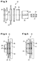
- the blow molding machine 1 has two on one with the foundation anchored base frame 2 movable yokes 3, 4 with carried by them Mold platen 5 and 6. Both the rear platen 5 and the front platen 6 only carries one for drawing reasons Tool half of a two-part blow molding tool shown schematically in dashed lines 7. Also not shown is a memory head or the like, the blow mold preforms and these from above into the tool area emits where they are blow molded in a known manner to a finished article be processed further.
- the electric traversing drive which causes the large stroke or travel path becomes through a small stroke in the fully closed working position of the Tool 7 effecting closing drive 10, which consists of two to the front Yoke 4 flanged hydraulic cylinders 11, which are high over short distances Generate clamping forces.
- Tool 7 is used to transmit the closing force locked, for which the side past from the front platen 6 Piston rods 12 at their free rod ends with a locking head 13 are formed, which in a complementary locking piece 14 of the opposite, engages rear platen 5 and after snapping the locking piece 14 is non-positively fixed.
- the locking pieces 14 are formed on locking bars 15 which are flanged to the yoke 3 with their rear end are.
- the tool 7 with its two tool halves defines according to FIG smallest mold thickness 16. If with a different, in Fig. 1 schematically dashed indicated shape thickness 17 to work, can Yokes 3, 4 should not be moved as close to each other as with the solid ones Lines of yokes 3, 4 shown; rather, they take a larger distance from each other. So that the locking heads 13 of the piston rods 12 nevertheless are brought into engagement with the locking pieces 14 of the locking bars 15 can, are two versions of a continuously adjustable mold thickness adjustment device 18 or 19 possible, both for the sake of simplicity in the blow molding machine 1 according to FIG. 1, but actually provided as an alternative become.
- the mold thickness adjustment device 18 consists of between the machine yokes 3, 4 and the mold mounting plates 5, 6 carried by these Spindle nut units 20 (see FIG. 3), each having a yoke-side, by means of a flange piece 21 to the yoke 3 or 4 threaded bolts 22, a clamping plate-side, concentrically enclosing the threaded bolt 22, in the exemplary embodiment according to FIGS. 2 to 5 which can be acted upon by a handwheel 23, axially immovable spindle nut 24 and a projecting into the Spindle nut 24 has inserted guide 25.
- a concentric on that Spindle nut 24 is attached to the coupling ring 26 with the platen 5 or 6 screwed and holds the nut rotatable, but axially immovable.
- an electric drive not shown -
- the threaded bolt 22 thus unscrews from the threaded nut 24 more or less - depending on the direction of rotation - and thus adjusts the associated one Mold platen 5 or 6 to the desired mold thickness 16 or 17 (see also Fig. 2); due to the infinitely variable adjustment, any intermediate layers between the smallest and largest mold thickness 16 or 17 set.
- the locking engagement is a larger one Stroke of the hydraulic cylinder 11 ensures whose piston rods 12 monitors of a position measuring system integrated in the cylinders 11 on the bottom, for example 31, which is connected to a higher-level machine control system, in exact position be advanced or extended accordingly.
- mold thickness adjuster 18 or 19 is in any case easily adjusted to different mold thicknesses achieved without complex To have to carry out adjustment work.
- the mold thickness settings are here does not depend on a certain grid size, and also are without further advantageous asymmetrical shape separations possible.
Landscapes
- Engineering & Computer Science (AREA)
- Mechanical Engineering (AREA)
- Manufacturing & Machinery (AREA)
- Moulds For Moulding Plastics Or The Like (AREA)
- Blow-Moulding Or Thermoforming Of Plastics Or The Like (AREA)
Applications Claiming Priority (2)
| Application Number | Priority Date | Filing Date | Title |
|---|---|---|---|
| DE19847306A DE19847306C1 (de) | 1998-10-14 | 1998-10-14 | Vorrichtung zum Anpassen einer Kunststoffverarbeitungsmaschine, insbesondere Blasformmaschine, an unterschiedliche Formdicken |
| DE19847306 | 1998-10-14 |
Publications (2)
| Publication Number | Publication Date |
|---|---|
| EP0993928A2 true EP0993928A2 (fr) | 2000-04-19 |
| EP0993928A3 EP0993928A3 (fr) | 2000-10-18 |
Family
ID=7884411
Family Applications (1)
| Application Number | Title | Priority Date | Filing Date |
|---|---|---|---|
| EP99118494A Withdrawn EP0993928A3 (fr) | 1998-10-14 | 1999-09-18 | Dispositif pour ajuster une machine de transformation des matières plastiques, en particulier une machine de moulage par soufflage, à des moules d'épaisseurs différentes |
Country Status (2)
| Country | Link |
|---|---|
| EP (1) | EP0993928A3 (fr) |
| DE (1) | DE19847306C1 (fr) |
Cited By (1)
| Publication number | Priority date | Publication date | Assignee | Title |
|---|---|---|---|---|
| WO2007134668A1 (fr) * | 2006-05-19 | 2007-11-29 | Extraplast Maschinen Gmbh | Dispositif de fermeture pour ouvrir et fermer un outil de moulage par soufflage avec assistance verrouillable de la force de fermeture |
Citations (1)
| Publication number | Priority date | Publication date | Assignee | Title |
|---|---|---|---|---|
| DE19516125C1 (de) | 1995-05-03 | 1996-06-05 | Battenfeld Fischer Blasform | Verfahren und Vorrichtung zum Schließen des Werkzeugs einer Kunststoffverarbeitungsmaschine |
Family Cites Families (5)
| Publication number | Priority date | Publication date | Assignee | Title |
|---|---|---|---|---|
| DD146404A1 (de) * | 1979-10-29 | 1981-02-11 | Klaus Fueller | Formschliesseinrichtung fuer spritzgiessmaschinen |
| US4645443A (en) * | 1984-12-29 | 1987-02-24 | Kabushiki Kaisha Aoki Seisakusho | Mold-thickness adjusting apparatus in mold clamping mechanism |
| JPH085060B2 (ja) * | 1988-04-14 | 1996-01-24 | 三菱重工業株式会社 | 型厚調製装置 |
| JP2511111B2 (ja) * | 1988-07-07 | 1996-06-26 | 三菱重工業株式会社 | 型厚調整装置 |
| DD291960A5 (de) * | 1990-02-15 | 1991-07-18 | Plastmaschinenwerk Schwerin,De | Spritzgiessmaschine zur kunststoffverarbeitung |
-
1998
- 1998-10-14 DE DE19847306A patent/DE19847306C1/de not_active Expired - Lifetime
-
1999
- 1999-09-18 EP EP99118494A patent/EP0993928A3/fr not_active Withdrawn
Patent Citations (1)
| Publication number | Priority date | Publication date | Assignee | Title |
|---|---|---|---|---|
| DE19516125C1 (de) | 1995-05-03 | 1996-06-05 | Battenfeld Fischer Blasform | Verfahren und Vorrichtung zum Schließen des Werkzeugs einer Kunststoffverarbeitungsmaschine |
Cited By (1)
| Publication number | Priority date | Publication date | Assignee | Title |
|---|---|---|---|---|
| WO2007134668A1 (fr) * | 2006-05-19 | 2007-11-29 | Extraplast Maschinen Gmbh | Dispositif de fermeture pour ouvrir et fermer un outil de moulage par soufflage avec assistance verrouillable de la force de fermeture |
Also Published As
| Publication number | Publication date |
|---|---|
| DE19847306C1 (de) | 2000-04-20 |
| EP0993928A3 (fr) | 2000-10-18 |
Similar Documents
| Publication | Publication Date | Title |
|---|---|---|
| EP2629954B1 (fr) | Dispositife d'injection avec presse à genouillère | |
| EP0508277B1 (fr) | Dispositif d'entraînement pour le déplacement et/ou la force de positionnement pour machines à mouler par injection | |
| EP0674985B1 (fr) | Unité de fermeture de moule pour une machine à mouler par injection et procédé pour son opération | |
| WO1994004337A1 (fr) | Unite de fermeture d'outils de formage pour presses d'injection | |
| EP0576837B1 (fr) | Machine à mouler par injection avec moule à étages | |
| EP0770468A2 (fr) | Machine à mouler par injection sans colonnes à deux plateaux | |
| EP1068060B1 (fr) | Unite de fermeture de moule pour une presse d'injection | |
| EP0631857A1 (fr) | Machine à mouler par injection les matières plastiques avec une unité de fermeture de moule | |
| EP0933181A2 (fr) | Dispositif de fermeture de moules pour la fabrication d'objets en résine thermoplastique | |
| DE19643366C2 (de) | Spritzgießmaschine mit einer Werkzeugschließeinrichtung | |
| DE69028634T2 (de) | Formschliesssystem | |
| EP0585671B1 (fr) | Unité d'éjection pour machines à mouler par injection | |
| EP1487626B1 (fr) | Dispositif de fermeture d'un moule a reglage en hauteur du moule, et procede permettant sa mise en action | |
| DE19510488C1 (de) | Vorrichtung zum Schließen von Formen für die Herstellung von Gegenständen aus Kunststoff | |
| DE19847306C1 (de) | Vorrichtung zum Anpassen einer Kunststoffverarbeitungsmaschine, insbesondere Blasformmaschine, an unterschiedliche Formdicken | |
| DE4328844C2 (de) | Spritzgießmaschine, insbesondere Kunststoffspritzgießmaschine | |
| EP1848577B1 (fr) | Machine de moulage par injection pour l'usinage de matieres plastiques | |
| DE102011014783B4 (de) | Verriegelungsvorrichtung für Holme einer Kunststoffverarbeitungsmaschine | |
| DE4411650A1 (de) | Formschließeinheit für eine Spritzgießmaschine | |
| DE1910459A1 (de) | Formschliess- und Formzuhaltevorrichtung fuer insbesondere Kunststoffe oder sich aehnlich verhaltende Massen verarbeitende Spritzgiessmaschinen oder Pressen | |
| DE19600461C2 (de) | Holmlose Zwei-Platten-Spritzgießmaschine mit einer beweglichen und einer feststehenden Formaufspannplatte | |
| DE19511917A1 (de) | Verfahren zum Betreiben einer Formschließeinheit für eine Spritzgießmaschine | |
| DE4216827C1 (de) | Formschließeinrichtung für Spritzgießmaschinen zur Aufbringung großer Schließkräfte | |
| EP0689924A1 (fr) | Unité de fermeture sans colonnes pour une machine destinée à la transformation de matière injectables | |
| EP0289857B1 (fr) | Unité de fermeture pour machines à mouler par injection |
Legal Events
| Date | Code | Title | Description |
|---|---|---|---|
| PUAI | Public reference made under article 153(3) epc to a published international application that has entered the european phase |
Free format text: ORIGINAL CODE: 0009012 |
|
| AK | Designated contracting states |
Kind code of ref document: A2 Designated state(s): DE FR IT |
|
| AX | Request for extension of the european patent |
Free format text: AL;LT;LV;MK;RO;SI |
|
| PUAL | Search report despatched |
Free format text: ORIGINAL CODE: 0009013 |
|
| AK | Designated contracting states |
Kind code of ref document: A3 Designated state(s): AT BE CH CY DE DK ES FI FR GB GR IE IT LI LU MC NL PT SE |
|
| AX | Request for extension of the european patent |
Free format text: AL;LT;LV;MK;RO;SI |
|
| 17P | Request for examination filed |
Effective date: 20001230 |
|
| AKX | Designation fees paid |
Free format text: DE FR IT |
|
| 17Q | First examination report despatched |
Effective date: 20010717 |
|
| STAA | Information on the status of an ep patent application or granted ep patent |
Free format text: STATUS: THE APPLICATION IS DEEMED TO BE WITHDRAWN |
|
| 18D | Application deemed to be withdrawn |
Effective date: 20020130 |