EP0993984A2 - Haltevorrichtung zur lösbaren Befestigung eines Kindersitzes an einem Fahrzeugsitz - Google Patents
Haltevorrichtung zur lösbaren Befestigung eines Kindersitzes an einem Fahrzeugsitz Download PDFInfo
- Publication number
- EP0993984A2 EP0993984A2 EP99116196A EP99116196A EP0993984A2 EP 0993984 A2 EP0993984 A2 EP 0993984A2 EP 99116196 A EP99116196 A EP 99116196A EP 99116196 A EP99116196 A EP 99116196A EP 0993984 A2 EP0993984 A2 EP 0993984A2
- Authority
- EP
- European Patent Office
- Prior art keywords
- holding
- vehicle seat
- seat
- fastening
- leg
- Prior art date
- Legal status (The legal status is an assumption and is not a legal conclusion. Google has not performed a legal analysis and makes no representation as to the accuracy of the status listed.)
- Granted
Links
Images


Classifications
-
- B—PERFORMING OPERATIONS; TRANSPORTING
- B60—VEHICLES IN GENERAL
- B60N—SEATS SPECIALLY ADAPTED FOR VEHICLES; VEHICLE PASSENGER ACCOMMODATION NOT OTHERWISE PROVIDED FOR
- B60N2/00—Seats specially adapted for vehicles; Arrangement or mounting of seats in vehicles
- B60N2/24—Seats specially adapted for vehicles; Arrangement or mounting of seats in vehicles for particular purposes or particular vehicles
- B60N2/26—Seats specially adapted for vehicles; Arrangement or mounting of seats in vehicles for particular purposes or particular vehicles for children
- B60N2/28—Seats readily mountable on, and dismountable from, existing seats or other parts of the vehicle
- B60N2/2821—Seats readily mountable on, and dismountable from, existing seats or other parts of the vehicle having a seat and a base part
- B60N2/2827—Seats readily mountable on, and dismountable from, existing seats or other parts of the vehicle having a seat and a base part part of the base being supported by the seat sub-frame
-
- B—PERFORMING OPERATIONS; TRANSPORTING
- B60—VEHICLES IN GENERAL
- B60N—SEATS SPECIALLY ADAPTED FOR VEHICLES; VEHICLE PASSENGER ACCOMMODATION NOT OTHERWISE PROVIDED FOR
- B60N2/00—Seats specially adapted for vehicles; Arrangement or mounting of seats in vehicles
- B60N2/24—Seats specially adapted for vehicles; Arrangement or mounting of seats in vehicles for particular purposes or particular vehicles
- B60N2/26—Seats specially adapted for vehicles; Arrangement or mounting of seats in vehicles for particular purposes or particular vehicles for children
- B60N2/28—Seats readily mountable on, and dismountable from, existing seats or other parts of the vehicle
- B60N2/2857—Seats readily mountable on, and dismountable from, existing seats or other parts of the vehicle characterised by the peculiar orientation of the child
- B60N2/286—Seats readily mountable on, and dismountable from, existing seats or other parts of the vehicle characterised by the peculiar orientation of the child forward facing
-
- B—PERFORMING OPERATIONS; TRANSPORTING
- B60—VEHICLES IN GENERAL
- B60N—SEATS SPECIALLY ADAPTED FOR VEHICLES; VEHICLE PASSENGER ACCOMMODATION NOT OTHERWISE PROVIDED FOR
- B60N2/00—Seats specially adapted for vehicles; Arrangement or mounting of seats in vehicles
- B60N2/24—Seats specially adapted for vehicles; Arrangement or mounting of seats in vehicles for particular purposes or particular vehicles
- B60N2/26—Seats specially adapted for vehicles; Arrangement or mounting of seats in vehicles for particular purposes or particular vehicles for children
- B60N2/28—Seats readily mountable on, and dismountable from, existing seats or other parts of the vehicle
- B60N2/2887—Fixation to a transversal anchorage bar, e.g. isofix
- B60N2/289—Fixation to a transversal anchorage bar, e.g. isofix coupled to the vehicle frame
Definitions
- the invention relates to a holding device for releasably fastening a Child seat on a vehicle seat according to the preamble of claim 1.
- EP 0 694 436 B1 describes a motor vehicle with at least one vehicle seat known which holding devices for a child seat attachable to it has, with two for holding the child seat on the backrest In the transverse direction, spaced-apart holding members are provided.
- Each holding member is - as seen in plan - approximately U-shaped Bracket formed, the two side legs of the bracket through sleeves on the seat side are passed through.
- the side legs have their free, protruding ends of each threaded sections on which from the back of the Backrest nuts are turned on.
- This arrangement is relatively complex because two screw fastenings are required to fix each holding element.
- the protruding screw fastenings on the back of the backrest also hide an increased risk of injury to passengers sitting behind.
- the object of the invention is to provide a holding member for fixing a child seat to simplify a vehicle seat and the associated screw fastening and to be injury-proof.
- each holding element as an annular holding eyelet and the assembly of the Front and the use of only one screw fastening per eyelet a simple, inexpensive holding device is created.
- an extended support section on the eyelet which is located on a If the vehicle seat is supported on the spacer, a tilt-proof support of the Holding eye achieved.
- the eyelet according to the invention is simple and inexpensive manufacture and assemble or disassemble easily. When the eyelet is removed, in the cutout on the vehicle seat uses a cover cap.
- a screw attachment is, for example, an integral part of the retaining eye Threaded pin provided, which can be screwed into a seat-side thread receptacle.
- the thread intake is closed by a liquid or gas tight Limbach nut, a welding nut or the like.
- the support portion of the retaining eyelet has a through hole through which a fastening screw for fixing the retaining eyelet can be passed is.
- the fastening screw is supported with a head section on the retaining eyelet, wherein an external thread section of the fastening screw into an internal thread of the Thread intake can be screwed.
- a welding screw can be attached to the vehicle seat Threaded shaft through the spacer and the support section of the eyelet protrudes, a nut being screwed onto the projecting threaded section is.
- the central axis of the annular retaining eye is achieved in that the retaining eye in two different positions can be mounted.
- One and the same eyelet is therefore for Different vehicle types can be used (e.g. convertible version and coupe version of one Vehicle with different positions of the attachment points for the child seat).
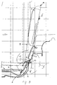
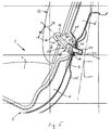
- a portion of a vehicle seat 1 is shown, which consists of a Seat part 2 and a backrest 3 is composed. It can be one Act front seat or a rear seat of a vehicle.
- the vehicle seat 1 is one of two existing rear seat system formed next to each other, wherein each seat part 2 comprises a seat recess 4 fixed on the body side, which for Passenger compartment 5 towards a foam-backed carpet 6 and a seat cushion 7 has.
- a swiveling backrest 3 is located above the seat recess 2 provided that about a horizontally oriented, transverse axis of rotation of an upright operating position A to the front down into a not shown Storage position can be folded down.
- a child seat 8 can be placed on the vehicle seat 1, the child seat 8 being above at least one holding device 9 is releasably connectable to the vehicle seat 1.
- the Child seat 8 is designed in a conventional manner as a one-piece bucket seat has a front catch table, not shown, which by means of a Lap belt on child seat 8 can be fixed.
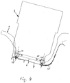
- the child seat 8 has two - in a rear area 10 below Seen vehicle transverse direction - spaced, protruding Attachment tabs 11, with each longitudinal end at the free end Fastening tab 11 an insertion opening 12 and a pivotable, not shown Pawl are arranged.
- each pawl engages in sections on Vehicle seat attached holding member 13.
- the pawl can be by means of a Move the device from a locked position to a release position in the the child seat 8 is removable from the vehicle seat 1.
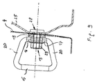
- each holding member 13 is formed by an annular holding eyelet 14 educated.
- the retaining eyelet 14 has a protruding, transverse, approximately horizontal aligned holding leg 15, which is seen circular in cross section is and has a diameter of 6 mm.
- the transverse rod-shaped Holding leg 15 has a transverse extent of at least 25 mm.
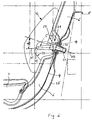
- annular retaining eyelet 14 comprises a shorter, approximately parallel to Holding leg 15 extending fastening leg 16, which is in a middle Area of its transverse extent has an expanding support section 17.
- the support section 17 is supported on a resting on the vehicle seat 1 annular spacer 18.
- Each ring-shaped eyelet 14 is of the Front of the vehicle seat 1 ago via only a screw fastening 19 on Vehicle seat 1 can be determined.
- Lateral inclined connecting sections 20 connect the upstream Holding leg 15 on both sides with the fastening leg 16 of the retaining eyelet 14.
- Die Connection sections 20 of the retaining eyelet 14 have an elliptical cross section, the height of the connecting sections 20 in the direction of the fastening leg 16 enlarged.
- the preferably formed by a forged part or a cast part When viewed from the top, the retaining eyelet 14 has approximately a trapezoidal contour, the transition regions from the holding leg 15 and the fastening leg 16 are rounded to the inclined connecting portions 20.
- the support section 17 of the fastening leg 16 has in the embodiment a cylindrical outer shape, wherein the outer diameter of the support section 17 approximately corresponds to the outer diameter of the spacer 18.
- the attachment points 21 for the eyelets 14 are in a rear upward projecting portion of the body-side recess 4 provided and something above the seat cushions 7.
- the foam-backed carpet 6 is in each case with a
- the screw fastening 19 comprises one the contact surface of the mounting leg 16 molded protruding Threaded pin 23, wherein the external thread of the threaded pin 23 in one fixed thread receptacle 24 of the vehicle seat 1 can be screwed in.
- the thread receptacle 24 has an internal thread and is by a closed limbach nut 25, a weld nut or the like is formed.
- the screw fastening 19 comprises a Fixing screw 26, which is with a head portion 27 on the Spacer 18 supports the opposite side of the support section 17, a Thread section of the fastening screw 26 through openings of the Support section 17, the spacer 18 and the seat 4 is passed and with the free end in the fixed threaded receptacle 24 of the vehicle seat 1 is screwed in.
- the screw fastening 19 comprises an Vehicle seat 1 attached welding screw, the threaded portion through openings the seat recess 4, the spacer 18 and the support section 17th is passed through, with a nut 29 on the projecting threaded section is turned, which is supported on the support portion 17 of the retaining eyelet 14.
- the eyelet 14 can be designed so that - seen in side view - the Central axis 30 of the screw fastening 19 with the central axis 31 of the annular Retaining eyelet collapses (not shown in detail).
- an additional trim part 32 is mounted on the vehicle seat 1, which the Holding eyelets 14 covers.
- the trim part 32 is locally with a recess 33 Mistake.
Landscapes
- Engineering & Computer Science (AREA)
- Health & Medical Sciences (AREA)
- Child & Adolescent Psychology (AREA)
- General Health & Medical Sciences (AREA)
- Aviation & Aerospace Engineering (AREA)
- Transportation (AREA)
- Mechanical Engineering (AREA)
- Seats For Vehicles (AREA)
Abstract
Description
- Fig. 1
- eine Seitenansicht auf einem Fahrzeugsitz mit einem aufgesetzten Kindersitz, teilweise im Schnitt, einer Cabrio-Version eines Fahrzeuges,
- Fig. 2
- eine Ansicht in Pfeilrichtung R der Fig. 1,
- Fig. 3
- eine Seitenansicht entsprechend Fig. 1 einer Coupe-Version eines Fahrzeuges,
- Fig. 4
- eine Ansicht in Pfeilrichtung S der Figur 3,
- Fig. 5
- einen Ausschnitt X der Fig. 1 in größerem Maßstab ohne aufgesetzten Kindersitz,
- Fig. 6
- einen Ausschnitt Y der Fig. 3 in größerem Maßstab ohne aufgesetzten Kindersitz,
- Fig. 7
- eine erste Ausführungsform der Halteöse mit angeformtem Gewindezapfen in drei verschiedenen Ansichten,
- Fig. 8
- eine zweite Ausführungsform der Halteöse mit einer Öffnung im Bereich des Auflageabschnitts zum Hindurchführen einer Befestigungsschraube in drei verschiedenen Ansichten,
- Fig. 9
- einen Schnitt durch eine dritte Ausführungsform der Schraubbefestigung mit einer am Fahrzeugsitz angebrachten Schweißsehraube.
Claims (9)
- Haltevorrichtung zur lösbaren Befestigung eines Kindersitzes an einem Fahrzeugsitz, wobei am Fahrzeugsitz wenigstens ein Halteorgan mittels Schraubbefestigung in Lage gehalten ist und das Halteorgan einen vorstehenden querverlaufenden, etwa horizontal ausgerichteten Halteschenkel aufweist, an dem der Kindersitz festlegbar ist, dadurch gekennzeichnet, daß jedes Halteorgan (13) durch eine ringförmige Halteöse (14) gebildet wird, wobei ein etwa parallel zum Halteschenkel (15) ausgerichteter Befestigungsschenkel (16) der Halteöse (14) von der Vorderseite des Fahrzeugsitzes (1) her durch lediglich eine Schraubbefestigung (19) am Fahrzeugsitz (1) festlegbar ist.
- Haltevorrichtung nach Anspruch 1, dadurch gekennzeichnet, daß die Halteöse (14) - in der Draufsicht gesehen - eine etwa trapezförmige Kontur aufweist, wobei der stabförmige Halteschenkel (15) eine größere Quererstreckung aufweist als der Befestigungsschenkel (16).
- Haltevorrichtung nach Anspruch 1, dadurch gekennzeichnet, daß in einem mittleren Bereich der Quererstreckung des Befestigungsschenkels (16) ein gegenüber dem Befestigungsschenkel (16) vergrößerter Auflageabschnitt (17) ausgebildet ist, der sich an einer am Fahrzeugsitz (1) aufliegenden Distanzscheibe (18) abstützt.
- Haltevorrichtung nach Anspruch 3, dadurch gekennzeichnet, daß der Auflageabschnitt (17) eine zylindrische Außenform aufweist.
- Haltevorrichtung nach den Ansprüchen 1, 3 und 4, dadurch gekennzeichnet, daß die Schraubbefestigung (19) einen an den Auflageabschnitt (17) angeformten vorstehenden Gewindezapfen (23) umfaßt, der in eine am Fahrzeugsitz (1) angebrachte Gewindeaufnahme (24) eindrehbar ist.
- Haltevorrichtung nach den Ansprüchen 1, 3 und 4, dadurch gekennzeichnet, daß die Schraubbefestigung (19) eine Befestigungsschraube (26) umfaßt, die sich mit einem Kopfabschnitt (27) an der der Distanzscheibe (18) abgekehrten Seite des Auflageabschnitts (17) abstützt, wobei ein Gewindeabschnitt der Befestigungsschraube (26) durch Öffnungen des Auflageabschnitts (17), der Distanzscheibe (18) und der Sitzmulde (4) hindurchgeführt und mit dem freien Ende in die feststehende Gewindeaufnahme (24) des Fahrzeugsitzes (1) eingedreht ist.
- Haltevorrichtung nach den Ansprüchen 5 oder 6, dadurch gekennzeichnet, daß die am Fahrzeugsitz (1) befestigte Gewindeaufnahme (24) durch eine geschlossene Limbachmutter eine Schweißmuttter oder dergleichen gebildet wird.
- Haltevorrichtung nach einem oder mehreren der vorangegangenen Ansprüche, dadurch gekennzeichnet, daß die Schraubbefestigung (19) eine am Fahrzeugsitz (1) befestigte Schweißschraube (28) umfaßt, deren Gewindeabschnitt durch die Sitzmulde (4), die Distanzscheibe (18) und den Auflageabschnitt (17) der Halteöse (14) hindurchgeführt ist, wobei auf den vorstehenden Gewindeabschnitt eine Mutter (29) aufgedreht ist.
- Haltevorrichtung nach einem oder mehreren der vorangegangenen Ansprüche, dadurch gekennzeichnet, daß - in der Seitenansicht gesehen - die den Halteschenkel (15) mit dem Befestigungsschenkel (16) verbindende Mittelachse (31) der Halteöse (14) unter einem Winkel α gegenüber der Mittelachse (30) der Schraubbefestigung (19) angestellt ist, wodurch die Halteöse (14) in zwei unterschiedlichen Betriebsstellungen B, C montierbar ist.
Applications Claiming Priority (2)
| Application Number | Priority Date | Filing Date | Title |
|---|---|---|---|
| DE19847956 | 1998-10-17 | ||
| DE19847956A DE19847956B4 (de) | 1998-10-17 | 1998-10-17 | Haltevorrichtung zur lösbaren Befestigung eines Kindersitzes an einem Fahrzeugsitz |
Publications (3)
| Publication Number | Publication Date |
|---|---|
| EP0993984A2 true EP0993984A2 (de) | 2000-04-19 |
| EP0993984A3 EP0993984A3 (de) | 2000-10-11 |
| EP0993984B1 EP0993984B1 (de) | 2008-02-06 |
Family
ID=7884824
Family Applications (1)
| Application Number | Title | Priority Date | Filing Date |
|---|---|---|---|
| EP99116196A Expired - Lifetime EP0993984B1 (de) | 1998-10-17 | 1999-08-24 | Haltevorrichtung zur lösbaren Befestigung eines Kindersitzes an einem Fahrzeugsitz |
Country Status (3)
| Country | Link |
|---|---|
| US (1) | US6334649B1 (de) |
| EP (1) | EP0993984B1 (de) |
| DE (2) | DE19847956B4 (de) |
Cited By (1)
| Publication number | Priority date | Publication date | Assignee | Title |
|---|---|---|---|---|
| WO2016046056A1 (de) * | 2014-09-25 | 2016-03-31 | Johnson Controls Gmbh | Befestigungsvorrichtung für einen kindersitz, insbesondere an einem fahrzeugsitz |
Families Citing this family (10)
| Publication number | Priority date | Publication date | Assignee | Title |
|---|---|---|---|---|
| DE19928862A1 (de) * | 1999-06-24 | 2001-01-04 | Keiper Gmbh & Co | Befestigungsvorrichtung für einen Kindersitz |
| DE10141541C1 (de) * | 2001-08-24 | 2003-01-30 | Audi Ag | Vorrichtung zur lösbaren Halterung von Gegenständen, insbesondere von Kindersitzen, an einem Fahrzeugsitz |
| US7044548B2 (en) | 2002-02-11 | 2006-05-16 | Graco Children's Products, Inc. | Child vehicle seat having permanently attached latch system |
| CA2372829A1 (en) * | 2002-02-19 | 2003-08-19 | Summo Steel Corporation | Weldless child safety restraint system for an automobile |
| US20040080193A1 (en) * | 2002-10-28 | 2004-04-29 | Johnson Controls Technology Company | Retainer and wire rod for child seat attachment |
| US7131693B2 (en) * | 2003-05-16 | 2006-11-07 | M & C Corporation | Restraint anchorage for a child restraint system |
| US6983526B2 (en) * | 2003-06-24 | 2006-01-10 | M & C Corporation | Cold formed latch wire |
| DE102010000780B4 (de) * | 2010-01-11 | 2012-01-12 | Takata-Petri Ag | Befestigungsvorrichtung für einen Fahrzeug-Kindersitz und Fahrzeug-Kindersitz |
| US9022340B2 (en) | 2011-03-21 | 2015-05-05 | Techform Products Limited | Formed tube with formed wire rivet |
| JP6276042B2 (ja) * | 2014-01-22 | 2018-02-07 | テイ・エス テック株式会社 | 乗物用シート |
Citations (1)
| Publication number | Priority date | Publication date | Assignee | Title |
|---|---|---|---|---|
| EP0694436B1 (de) | 1994-07-26 | 1998-04-22 | LEAR CORPORATION ITALIA S.p.A. | Vorrichtung zum Schnellverbinden eines Kindersitzes mit einem Kraftwagensitz |
Family Cites Families (15)
| Publication number | Priority date | Publication date | Assignee | Title |
|---|---|---|---|---|
| US2868309A (en) * | 1956-01-31 | 1959-01-13 | Company The Royal Trust | Ignition safety system cut-out switch |
| US3369842A (en) * | 1967-01-17 | 1968-02-20 | American Safety Equip | Adapter device for releasable attachment of a shoulder strap to a lap-type safety belt |
| US4005904A (en) * | 1975-06-24 | 1977-02-01 | Sigmatex, A.G. | Run through bracket |
| US4243266A (en) * | 1978-03-31 | 1981-01-06 | Kangol Magnet Limited | Seat belt system and connector therefor |
| FR2428444A1 (fr) * | 1978-06-12 | 1980-01-11 | Repa Feinstanzwerk Gmbh | Renvoi pour une ceinture de securite |
| DE3306095A1 (de) * | 1983-02-22 | 1984-08-30 | Repa Feinstanzwerk Gmbh, 7071 Alfdorf | Umlenkbeschlag fuer sicherheitsgurte in kraftfahrzeugen |
| JP2749478B2 (ja) * | 1992-03-13 | 1998-05-13 | 株式会社東海理化電機製作所 | 子供用シート |
| GB9307446D0 (en) * | 1993-04-08 | 1993-06-02 | Britax Excelsior | Child safety seat |
| GB9320169D0 (en) * | 1993-09-30 | 1993-11-17 | Britax Excelsior | Child safety seat |
| GB9414418D0 (en) * | 1994-07-16 | 1994-09-07 | Britax Excelsior | Child safety seat |
| EP0703113A3 (de) * | 1994-08-25 | 1996-11-27 | Britax Roemer Kindersicherheit Gmbh | Kindersicherheitssitz für Fahrzeuge |
| GB9424050D0 (en) * | 1994-11-29 | 1995-01-18 | Britax Roemer Kindersicherheit Gmbh | Child safety seat |
| DE19708044C1 (de) * | 1997-02-28 | 1998-06-10 | Audi Ag | Befestigungsvorrichtung an einem Kindersitz und an einer hinteren Kraftfahrzeugsitzbank mit umklappbarer Lehne |
| DE19723345C1 (de) * | 1997-06-04 | 1998-07-09 | Faure Bertrand Sitztech Gmbh | Schloßmechanismus zur lösbaren Befestigung eines Kindersitzes auf einem Fahrzeugsitz |
| GB2329114A (en) * | 1997-09-11 | 1999-03-17 | Ford Motor Co | Child seat anchorage |
-
1998
- 1998-10-17 DE DE19847956A patent/DE19847956B4/de not_active Expired - Fee Related
-
1999
- 1999-08-24 DE DE59914641T patent/DE59914641D1/de not_active Expired - Lifetime
- 1999-08-24 EP EP99116196A patent/EP0993984B1/de not_active Expired - Lifetime
- 1999-10-18 US US09/421,350 patent/US6334649B1/en not_active Expired - Fee Related
Patent Citations (1)
| Publication number | Priority date | Publication date | Assignee | Title |
|---|---|---|---|---|
| EP0694436B1 (de) | 1994-07-26 | 1998-04-22 | LEAR CORPORATION ITALIA S.p.A. | Vorrichtung zum Schnellverbinden eines Kindersitzes mit einem Kraftwagensitz |
Cited By (1)
| Publication number | Priority date | Publication date | Assignee | Title |
|---|---|---|---|---|
| WO2016046056A1 (de) * | 2014-09-25 | 2016-03-31 | Johnson Controls Gmbh | Befestigungsvorrichtung für einen kindersitz, insbesondere an einem fahrzeugsitz |
Also Published As
| Publication number | Publication date |
|---|---|
| EP0993984A3 (de) | 2000-10-11 |
| US6334649B1 (en) | 2002-01-01 |
| EP0993984B1 (de) | 2008-02-06 |
| DE19847956B4 (de) | 2006-05-24 |
| DE19847956A1 (de) | 2000-04-20 |
| DE59914641D1 (de) | 2008-03-20 |
Similar Documents
| Publication | Publication Date | Title |
|---|---|---|
| DE10035258B4 (de) | Verriegelungsvorrichtung für einen Fahrzeugsitz | |
| EP1954523B1 (de) | Drehbarer kindersitz für kraftfahrzeuge | |
| DE29700908U1 (de) | Gurtschloß mit Befestigungsbeschlag | |
| EP0993984B1 (de) | Haltevorrichtung zur lösbaren Befestigung eines Kindersitzes an einem Fahrzeugsitz | |
| DE102004015585B4 (de) | Gelenkkonstruktion für Sitzrückenlehnen | |
| DE69605690T2 (de) | Lösbarer Befestigungszusammenbau | |
| DE102010003664A1 (de) | Sitzanordnung mit einer Kopfstützenanordnung mit mehreren Positionen | |
| DE102008024020A1 (de) | Rastbeschlag für einen Fahrzeugsitz | |
| EP0791499B1 (de) | Kraftfahrzeug mit zumindest einem beifahrerseitigen Fahrzeugsitz | |
| DE29800290U1 (de) | Verstelleinrichtung für eine Fahrzeugsitz-Rückenlehne | |
| DE102006003243A1 (de) | Beschlag für einen Fahrzeugsitz | |
| DE102005042623B4 (de) | Kindersitzverankerung | |
| DE102018123716B4 (de) | Sitzchassis für einen Kraftfahrzeugsitz | |
| DE2642110C2 (de) | ||
| DE202022101820U1 (de) | Rückenlehne eines Fahrzeugsitzes, Fahrzeugsitz, der eine solche Rückenlehne umfasst und Sitzbaugruppe, die einen solchen Sitz umfasst | |
| DE19509159A1 (de) | Kopfstützenanordnung | |
| DE4039692A1 (de) | Halterung | |
| DE102019004287A1 (de) | Verankerungsanordnung zum Verankern eines Gurtverankerungselementes für einen Sicherheitsgurt an einem Fahrzeugbauteil | |
| DE4304725C2 (de) | Neigungsverstellbeschlag für die Rückenlehne von Kfz-Sitzen | |
| DE3810612C2 (de) | Verstellbeschlag für Sitze mit neigungseinstellbarer Lehne | |
| DE102005033068B3 (de) | Beschlag für einen Fahrzeugsitz | |
| DE102006059096A1 (de) | Baugruppe zur fahrzeugseitigen Befestigung eines Gurtschlosses | |
| EP0761512A1 (de) | Kraftfahrzeug mit höheneinstellbarem Umlenkbeschlag für Sicherheitsgurte | |
| DE102005025002A1 (de) | Beschlag für einen Fahrzeugsitz | |
| DE19628763B4 (de) | Kraftfahrzeug mit zumindest einem Fahrzeugsitz |
Legal Events
| Date | Code | Title | Description |
|---|---|---|---|
| PUAI | Public reference made under article 153(3) epc to a published international application that has entered the european phase |
Free format text: ORIGINAL CODE: 0009012 |
|
| AK | Designated contracting states |
Kind code of ref document: A2 Designated state(s): DE ES FR GB |
|
| AX | Request for extension of the european patent |
Free format text: AL;LT;LV;MK;RO;SI |
|
| PUAL | Search report despatched |
Free format text: ORIGINAL CODE: 0009013 |
|
| AK | Designated contracting states |
Kind code of ref document: A3 Designated state(s): AT BE CH CY DE DK ES FI FR GB GR IE IT LI LU MC NL PT SE |
|
| AX | Request for extension of the european patent |
Free format text: AL;LT;LV;MK;RO;SI |
|
| 17P | Request for examination filed |
Effective date: 20010315 |
|
| AKX | Designation fees paid |
Free format text: DE ES FR GB |
|
| GRAP | Despatch of communication of intention to grant a patent |
Free format text: ORIGINAL CODE: EPIDOSNIGR1 |
|
| GRAS | Grant fee paid |
Free format text: ORIGINAL CODE: EPIDOSNIGR3 |
|
| GRAA | (expected) grant |
Free format text: ORIGINAL CODE: 0009210 |
|
| AK | Designated contracting states |
Kind code of ref document: B1 Designated state(s): DE ES FR GB |
|
| REG | Reference to a national code |
Ref country code: GB Ref legal event code: FG4D Free format text: NOT ENGLISH |
|
| REF | Corresponds to: |
Ref document number: 59914641 Country of ref document: DE Date of ref document: 20080320 Kind code of ref document: P |
|
| RAP2 | Party data changed (patent owner data changed or rights of a patent transferred) |
Owner name: DR. ING. H.C. F. PORSCHE AKTIENGESELLSCHAFT |
|
| RAP2 | Party data changed (patent owner data changed or rights of a patent transferred) |
Owner name: DR. ING. H.C. F. PORSCHE AKTIENGESELLSCHAFT |
|
| PG25 | Lapsed in a contracting state [announced via postgrant information from national office to epo] |
Ref country code: ES Free format text: LAPSE BECAUSE OF FAILURE TO SUBMIT A TRANSLATION OF THE DESCRIPTION OR TO PAY THE FEE WITHIN THE PRESCRIBED TIME-LIMIT Effective date: 20080517 |
|
| ET | Fr: translation filed | ||
| PGFP | Annual fee paid to national office [announced via postgrant information from national office to epo] |
Ref country code: FR Payment date: 20080813 Year of fee payment: 10 |
|
| PLBE | No opposition filed within time limit |
Free format text: ORIGINAL CODE: 0009261 |
|
| STAA | Information on the status of an ep patent application or granted ep patent |
Free format text: STATUS: NO OPPOSITION FILED WITHIN TIME LIMIT |
|
| PGFP | Annual fee paid to national office [announced via postgrant information from national office to epo] |
Ref country code: GB Payment date: 20080821 Year of fee payment: 10 |
|
| 26N | No opposition filed |
Effective date: 20081107 |
|
| REG | Reference to a national code |
Ref country code: FR Ref legal event code: TP |
|
| REG | Reference to a national code |
Ref country code: FR Ref legal event code: CD |
|
| PGFP | Annual fee paid to national office [announced via postgrant information from national office to epo] |
Ref country code: DE Payment date: 20090806 Year of fee payment: 11 |
|
| GBPC | Gb: european patent ceased through non-payment of renewal fee |
Effective date: 20090824 |
|
| REG | Reference to a national code |
Ref country code: FR Ref legal event code: ST Effective date: 20100430 |
|
| PG25 | Lapsed in a contracting state [announced via postgrant information from national office to epo] |
Ref country code: FR Free format text: LAPSE BECAUSE OF NON-PAYMENT OF DUE FEES Effective date: 20090831 |
|
| PG25 | Lapsed in a contracting state [announced via postgrant information from national office to epo] |
Ref country code: GB Free format text: LAPSE BECAUSE OF NON-PAYMENT OF DUE FEES Effective date: 20090824 |
|
| REG | Reference to a national code |
Ref country code: DE Ref legal event code: R119 Ref document number: 59914641 Country of ref document: DE Effective date: 20110301 |
|
| PG25 | Lapsed in a contracting state [announced via postgrant information from national office to epo] |
Ref country code: DE Free format text: LAPSE BECAUSE OF NON-PAYMENT OF DUE FEES Effective date: 20110301 |