EP0994014A1 - Dispositif antivibratoire hydraulique pour roue avant et/ou arrière d'une véhicule à deux roues - Google Patents
Dispositif antivibratoire hydraulique pour roue avant et/ou arrière d'une véhicule à deux roues Download PDFInfo
- Publication number
- EP0994014A1 EP0994014A1 EP98811032A EP98811032A EP0994014A1 EP 0994014 A1 EP0994014 A1 EP 0994014A1 EP 98811032 A EP98811032 A EP 98811032A EP 98811032 A EP98811032 A EP 98811032A EP 0994014 A1 EP0994014 A1 EP 0994014A1
- Authority
- EP
- European Patent Office
- Prior art keywords
- control valve
- fork
- tube
- damping
- oil
- Prior art date
- Legal status (The legal status is an assumption and is not a legal conclusion. Google has not performed a legal analysis and makes no representation as to the accuracy of the status listed.)
- Withdrawn
Links
Images

Classifications
-
- B—PERFORMING OPERATIONS; TRANSPORTING
- B62—LAND VEHICLES FOR TRAVELLING OTHERWISE THAN ON RAILS
- B62K—CYCLES; CYCLE FRAMES; CYCLE STEERING DEVICES; RIDER-OPERATED TERMINAL CONTROLS SPECIALLY ADAPTED FOR CYCLES; CYCLE AXLE SUSPENSIONS; CYCLE SIDECARS, FORECARS, OR THE LIKE
- B62K25/00—Axle suspensions
- B62K25/04—Axle suspensions for mounting axles resiliently on cycle frame or fork
- B62K25/06—Axle suspensions for mounting axles resiliently on cycle frame or fork with telescopic fork, e.g. including auxiliary rocking arms
- B62K25/10—Axle suspensions for mounting axles resiliently on cycle frame or fork with telescopic fork, e.g. including auxiliary rocking arms for rear wheel
-
- B—PERFORMING OPERATIONS; TRANSPORTING
- B62—LAND VEHICLES FOR TRAVELLING OTHERWISE THAN ON RAILS
- B62K—CYCLES; CYCLE FRAMES; CYCLE STEERING DEVICES; RIDER-OPERATED TERMINAL CONTROLS SPECIALLY ADAPTED FOR CYCLES; CYCLE AXLE SUSPENSIONS; CYCLE SIDECARS, FORECARS, OR THE LIKE
- B62K25/00—Axle suspensions
- B62K25/04—Axle suspensions for mounting axles resiliently on cycle frame or fork
-
- B—PERFORMING OPERATIONS; TRANSPORTING
- B62—LAND VEHICLES FOR TRAVELLING OTHERWISE THAN ON RAILS
- B62K—CYCLES; CYCLE FRAMES; CYCLE STEERING DEVICES; RIDER-OPERATED TERMINAL CONTROLS SPECIALLY ADAPTED FOR CYCLES; CYCLE AXLE SUSPENSIONS; CYCLE SIDECARS, FORECARS, OR THE LIKE
- B62K25/00—Axle suspensions
- B62K25/04—Axle suspensions for mounting axles resiliently on cycle frame or fork
- B62K25/06—Axle suspensions for mounting axles resiliently on cycle frame or fork with telescopic fork, e.g. including auxiliary rocking arms
- B62K25/08—Axle suspensions for mounting axles resiliently on cycle frame or fork with telescopic fork, e.g. including auxiliary rocking arms for front wheel
-
- F—MECHANICAL ENGINEERING; LIGHTING; HEATING; WEAPONS; BLASTING
- F16—ENGINEERING ELEMENTS AND UNITS; GENERAL MEASURES FOR PRODUCING AND MAINTAINING EFFECTIVE FUNCTIONING OF MACHINES OR INSTALLATIONS; THERMAL INSULATION IN GENERAL
- F16F—SPRINGS; SHOCK-ABSORBERS; MEANS FOR DAMPING VIBRATION
- F16F13/00—Units comprising springs of the non-fluid type as well as vibration-dampers, shock-absorbers, or fluid springs
-
- F—MECHANICAL ENGINEERING; LIGHTING; HEATING; WEAPONS; BLASTING
- F16—ENGINEERING ELEMENTS AND UNITS; GENERAL MEASURES FOR PRODUCING AND MAINTAINING EFFECTIVE FUNCTIONING OF MACHINES OR INSTALLATIONS; THERMAL INSULATION IN GENERAL
- F16F—SPRINGS; SHOCK-ABSORBERS; MEANS FOR DAMPING VIBRATION
- F16F9/00—Springs, vibration-dampers, shock-absorbers, or similarly-constructed movement-dampers using a fluid or the equivalent as damping medium
- F16F9/10—Springs, vibration-dampers, shock-absorbers, or similarly-constructed movement-dampers using a fluid or the equivalent as damping medium using liquid only; using a fluid of which the nature is immaterial
- F16F9/14—Devices with one or more members, e.g. pistons, vanes, moving to and fro in chambers and using throttling effect
- F16F9/16—Devices with one or more members, e.g. pistons, vanes, moving to and fro in chambers and using throttling effect involving only straight-line movement of the effective parts
-
- F—MECHANICAL ENGINEERING; LIGHTING; HEATING; WEAPONS; BLASTING
- F16—ENGINEERING ELEMENTS AND UNITS; GENERAL MEASURES FOR PRODUCING AND MAINTAINING EFFECTIVE FUNCTIONING OF MACHINES OR INSTALLATIONS; THERMAL INSULATION IN GENERAL
- F16F—SPRINGS; SHOCK-ABSORBERS; MEANS FOR DAMPING VIBRATION
- F16F9/00—Springs, vibration-dampers, shock-absorbers, or similarly-constructed movement-dampers using a fluid or the equivalent as damping medium
- F16F9/32—Details
- F16F9/44—Means on or in the damper for manual or non-automatic adjustment; such means combined with temperature correction
- F16F9/46—Means on or in the damper for manual or non-automatic adjustment; such means combined with temperature correction allowing control from a distance, i.e. location of means for control input being remote from site of valves, e.g. on damper external wall
-
- B—PERFORMING OPERATIONS; TRANSPORTING
- B60—VEHICLES IN GENERAL
- B60G—VEHICLE SUSPENSION ARRANGEMENTS
- B60G2300/00—Indexing codes relating to the type of vehicle
- B60G2300/12—Cycles; Motorcycles
-
- B—PERFORMING OPERATIONS; TRANSPORTING
- B60—VEHICLES IN GENERAL
- B60G—VEHICLE SUSPENSION ARRANGEMENTS
- B60G2500/00—Indexing codes relating to the regulated action or device
- B60G2500/10—Damping action or damper
-
- B—PERFORMING OPERATIONS; TRANSPORTING
- B62—LAND VEHICLES FOR TRAVELLING OTHERWISE THAN ON RAILS
- B62K—CYCLES; CYCLE FRAMES; CYCLE STEERING DEVICES; RIDER-OPERATED TERMINAL CONTROLS SPECIALLY ADAPTED FOR CYCLES; CYCLE AXLE SUSPENSIONS; CYCLE SIDECARS, FORECARS, OR THE LIKE
- B62K25/00—Axle suspensions
- B62K25/04—Axle suspensions for mounting axles resiliently on cycle frame or fork
- B62K2025/048—Axle suspensions for mounting axles resiliently on cycle frame or fork with suspension manual adjustment details
Definitions
- the present invention relates to a device for hydraulic damping of the Front and / or rear wheel of a two-wheeled vehicle.
- the invention is now an object of a device in the preamble of To create claim 1 type, in which the disadvantages mentioned avoided and with which the damping can be easily adjusted.
- the device has at least one externally operated control valve, by means of which is the amount of oil displaced per unit of time and decisive for the damping is variable, the prerequisite is created so that the damping during the trip can be adjusted.
- a driver leading to the handlebar can be used to actuate the control valve Cable pull are provided.
- the control valve or the actuating means can both for adjustment in steps as well as for continuous adjustment be trained.
- control valve is hydraulic is connected to both fork halves of a wheel fork.
- a fork can be constructed symmetrically and, unlike a fork, teaches that only the damping of one fork half can be influenced, dynamic driving advantages.
- control valve is particularly used to change the damping during compression is proposed in a further preferred embodiment Interior of the lifting tube via a hole hydraulically with the space between To connect standpipe and lifting tube and an adjustable throttle to To change the flow cross section of the bore. Because the fork is like this is designed to force oil to flow through this hole when rebounding the damping during rebound can be changed using this throttle element or be set.
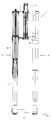
- the in the sprung out State shown front fork 1 has a left fork half 2 and a right Half of fork 3.
- a middle tube 5 is arranged between the fork halves 2, 3, that over an upper fork glasses 7 and a lower fork glasses 8 mechanically with the two fork halves 2, 3 is connected.
- At the upper end of the center tube 5 is in Normally the handlebars (not shown in Fig. 1) attached.
- the fork half 2 has a standpipe 10 which is fixed in the two fork glasses 7, 8.
- the standpipe 10 encompasses a dip tube 11, at the lower end of a wheel hub flange 12 for fastening the front wheel (not shown) is arranged.
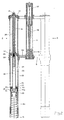
- FIG. 2 shows the upper part of the front wheel fork 1 according to FIG. 1 in an enlarged manner Representation, wherein the front wheel fork 1 is shown in a slightly compressed state is.
- the standpipe 10 is closed at the upper end by a cover 14.
- a support tube 16 is fixed, which at the lower end in a Recording 17 is supported.
- a lifting tube 18 is also supported in the receptacle 17.
- a piston 20 is arranged, one has an extension 19 provided with an external thread. This extension 19 is in an internal thread of the lifting tube 18 is screwed in.
- the extension 19 of the piston 20 has a T-shaped through hole 21 through which the interior 23 of the lifting tube 18 with the space 24a between the lifting tube 18 and the standpipe 10 is connected.
- a compression spring 22 is supported, which the The rebound process is supported by pressing the dip tube 11 downward.
- the Immersion tube 11 is provided at the upper end with a closure cap 33, which has four vertical flow openings 35, only their being shown in this illustration two can be seen.
- the space between the lifting tube 18 and the standpipe 10 is open the top of the cap 33 with the reference numeral 24 and on the bottom the cap 33 with the reference numeral 24a.
- To close the flow openings 35 is formed by an annular disk 26 and provided by a spring 27 loaded check valve, which at Compression opens and closes when rebounding.
- the lifting tube 18 is in the range of provided at the top with a radial bore 28, the flow cross section can be changed by means of an adjusting screw 29.
- the set screw 29 is with a Control tube 30 connected, which passed through the lid 14 and at the end with an actuator 31 is provided.
- a hydraulic control valve 40 is received, which via a channel 39 let into the lower fork glasses 8 with the space 24 between Lift tube 18 and standpipe 10 is hydraulically connected.
- the control valve 40 is there also connected to the right fork half 3.
- the control valve 40 is over a cable 37 leading to the handlebar (not visible) can be actuated.
- a compression spring 48 ensures the resetting of the cable 37.
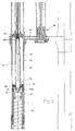
- FIG 3 is a further enlarged view of the central part of the front fork 1 can be seen. From this illustration it can be seen that the extension 19 of the piston 20 let through hole 21 into the space 24a opens, and that the check valve 26 in the flow openings 35 of the cap 33 is arranged.
- the immersion tube 11 dips into the standpipe 10.
- the standpipe 10 creates an overpressure in the standpipe 10, through which the check valve 26 in the cap 33 opens and the flow openings 35 open, so that Oil through the cap 33 from the upper part 24 of the gap can flow into the lower part 24a.
- the cap works when the fork is deflected 33 as a throttle, which significantly influences the damping.
- immerses the dip tube 11 in the standpipe 10 on the one hand creates an overpressure in the Gap 24.
- the total gap 24, 24a becomes dependent the immersion depth and the wall thickness of the immersion tube 11 - reduced. This causes, that the oil received in the space 24 through the bore 39 in the Center tube 5 escapes where it flows through the control valve 40, which then is explained in more detail with reference to FIG. 5.
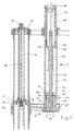
- Fig. 4 shows the central tube 5 in an overall view. That in the center tube 5 control valve 40 includes a hollow cylindrical sleeve 41, into which two radially extending flow openings 42 are let. In the T-shaped designed sleeve 41 is a control slide which can be actuated via the cable pull 37 44 movably added.
- the control slide 44 has one with respect to it Longitudinal central axis conical control surface 45, by means of which the Passage cross section of the flow openings 42 when moving the control slide 44 is very finely adjustable.
- the center tube 5 is on the underside of one Insert 47 closed.
- This insert 47 has two radial bores 49 on which the respective channel 39 embedded in the lower fork glasses 8 connect an annular space 50 that leads past the outside of the sleeve 41.
- the sleeve 41 has four axial bores 48 which define the annular space 50 connect to a storage chamber 54. Of the four axial bores 48 are only two of them can be seen from this illustration.
- a check valve with an L-shaped cross section 52 provided, which is loaded by a compression spring. The compression spring is not shown in favor of a clear presentation. After all, it is Sleeve 41 provided with a central bore 51 which the flow openings 42 connect to the storage chamber 54.
- the center tube 5 is closed on the top by a cover 58 through which the cable pull 37 is guided. Between the cover 58 and an accumulator piston 59, an accumulator piston tube 60 is mounted, the accumulator piston 60 has two ring channels 62 and 63 for receiving 0-ring seals, which the latter, however, were not drawn in in favor of a clear presentation.
- the pressure accumulator piston 59 is also included the pressure piston tube 60 pushed into the center tube 5 and with the cover 58 locked. By pushing in the air is compressed above the oil level 55, so that a pressure accumulator forms in the storage chamber 54, which in the idle state, depending on the length of the pressure piston tube 60 and the height of the oil level 55, approx. 1 to 2 bar overpressure.
- the left half of the control valve 40 shows its position during compression while the right half of the Control valve 40 shows the position when rebounding.
- the direction of flow the oil is indicated by an arrow 65.
- This oil gets through the radial Bore 49 in the annular space 50.
- the oil flows over from this annular space 50 the flow opening 42 and the central bore 51 in the sleeve 41 in the storage chamber 54. Since the check valve 52 is closed when the fork is compressed is, the control valve 40 acts as a throttle. The throttling effect can be shifted of the control slide 44 can be varied.
- Moving the control spool 44 causes a change in the passage cross section of the flow openings 42 and thus also the displaceable per unit of time and for the damping relevant amount of oil. Due to the conical control surface 45, the Passage cross section of the flow openings 42 can be metered very finely. Through a Closing the flow openings 42 can also block the fork.
- the device described can also be used to adjust the damping at a hydraulically suspended rear wheel.
- the rear wheel has an articulated lever mechanism attached to the vehicle frame supported and with a central hydraulic strut is provided, or whether the rear wheel is analogous to the front wheel described two wheel fork halves is supported.
- a common one Control valve has the advantage of simple operation by, for example, over a lever arranged on the handlebar, the front and rear wheel damping at the same time can be changed. With separate control valves for the front and rear wheel their damping can be adjusted separately.
- an overpressure can be generated in the immersion tube.
- the sealing cap could also be used, for example 33 of the dip tube 11 are replaced. For example a cap 33 with larger or smaller flow openings 35 is used become.
- Another lifting tube 18 with a larger or smaller or at a different location arranged radial bore 28 used become.
- the suspension travel can also be changed by replacing the lifting tube 18 become.
- Another variant is that instead of a mechanically operated spool for example an electromechanically operated control slide or a deflectable membrane can be used.
- a mechanically operated spool for example an electromechanically operated control slide or a deflectable membrane can be used.
- control valve 40 could instead of in the center tube 5 in the upper part of one Wheel fork half are arranged.
- wheel fork damping according to the invention is described on a mountain bike , it can be used for any two-wheeled vehicle - or possibly also for a three-wheeled vehicle - in which a single wheel is guided in a wheel fork. Furthermore are within the scope of protection defined in the claims Embodiments of the device that deviate from the previous example conceivable.
Landscapes
- Engineering & Computer Science (AREA)
- General Engineering & Computer Science (AREA)
- Mechanical Engineering (AREA)
- Fluid-Damping Devices (AREA)
- Axle Suspensions And Sidecars For Cycles (AREA)
Priority Applications (3)
| Application Number | Priority Date | Filing Date | Title |
|---|---|---|---|
| EP98811032A EP0994014A1 (fr) | 1998-10-16 | 1998-10-16 | Dispositif antivibratoire hydraulique pour roue avant et/ou arrière d'une véhicule à deux roues |
| CA 2253659 CA2253659A1 (fr) | 1998-10-16 | 1998-11-04 | Appareil d'amortissement hydraulique du mouvement des roues avant et/ou arriere d'un vehicule a deux roues |
| JP10325552A JP2000118470A (ja) | 1998-10-16 | 1998-11-16 | 二輪車の前及び/又は後輪の動作の流体圧式減衰装置 |
Applications Claiming Priority (1)
| Application Number | Priority Date | Filing Date | Title |
|---|---|---|---|
| EP98811032A EP0994014A1 (fr) | 1998-10-16 | 1998-10-16 | Dispositif antivibratoire hydraulique pour roue avant et/ou arrière d'une véhicule à deux roues |
Publications (1)
| Publication Number | Publication Date |
|---|---|
| EP0994014A1 true EP0994014A1 (fr) | 2000-04-19 |
Family
ID=8236387
Family Applications (1)
| Application Number | Title | Priority Date | Filing Date |
|---|---|---|---|
| EP98811032A Withdrawn EP0994014A1 (fr) | 1998-10-16 | 1998-10-16 | Dispositif antivibratoire hydraulique pour roue avant et/ou arrière d'une véhicule à deux roues |
Country Status (3)
| Country | Link |
|---|---|
| EP (1) | EP0994014A1 (fr) |
| JP (1) | JP2000118470A (fr) |
| CA (1) | CA2253659A1 (fr) |
Cited By (6)
| Publication number | Priority date | Publication date | Assignee | Title |
|---|---|---|---|---|
| DE10224093A1 (de) * | 2002-05-31 | 2003-12-11 | Bayerische Motoren Werke Ag | Gabelbrücke |
| EP1526067A1 (fr) * | 2003-10-20 | 2005-04-27 | Delphi Technologies, Inc. | Suspension avant pour véhicules à roue avant dirigeable |
| ITMI20090185A1 (it) * | 2009-02-12 | 2010-08-13 | Francesco Zannini | Dispositivo di sospensione regolabile per veicoli. |
| EP2108577A3 (fr) * | 2008-04-11 | 2011-01-26 | Shimano, Inc. | Suspension de bicyclette dotée d'un réglage de course et d'amortissement |
| CN109649562A (zh) * | 2019-01-05 | 2019-04-19 | 河北兴江机械有限公司 | 一种三轮车的前减震器总成 |
| FR3098266A1 (fr) * | 2019-07-04 | 2021-01-08 | Jsa | Amortisseur hydraulique télescopique multi-tarages |
Families Citing this family (5)
| Publication number | Priority date | Publication date | Assignee | Title |
|---|---|---|---|---|
| DE60323515D1 (de) * | 2003-12-16 | 2008-10-23 | Ducati Motor Holding Spa | Vorderradaufhängung für Motorrad |
| JP6349116B2 (ja) * | 2014-03-17 | 2018-06-27 | Kyb株式会社 | フロントフォーク |
| CN104632993A (zh) * | 2014-12-04 | 2015-05-20 | 安徽乐库智能停车设备有限公司 | 一种防抖动的机械缓冲装置 |
| KR101942233B1 (ko) * | 2018-01-28 | 2019-01-24 | 김원봉 | 자전거 프런트 서스펜션 포크 |
| KR102367011B1 (ko) * | 2021-09-24 | 2022-02-24 | 김성환 | 자기유변 유체 기반의 가변 감쇠력을 가지는, 전기 자전거를 포함한 이륜 차량용 스마트 서스펜션 시스템과 이를 포함하는 이륜차 |
Citations (6)
| Publication number | Priority date | Publication date | Assignee | Title |
|---|---|---|---|---|
| JPS57107449A (en) * | 1980-12-23 | 1982-07-03 | Showa Mfg Co Ltd | Adjuster for damping force of damper |
| DE3143126A1 (de) * | 1981-10-30 | 1983-05-11 | Robert Bosch Gmbh, 7000 Stuttgart | Vorrichtung zum veraendern des federvolumens |
| US4561669A (en) * | 1982-12-30 | 1985-12-31 | Simons Stephen W | Motorcycle fork |
| EP0424284A1 (fr) * | 1989-10-18 | 1991-04-24 | Jean-Marc Guyenard | Dispositif de réglage de pression pour fourche de motocyclette |
| DE4123643A1 (de) * | 1990-11-30 | 1992-06-04 | Peter Kleinbreuer | Fahrrad |
| WO1993023283A2 (fr) * | 1992-05-13 | 1993-11-25 | Peter Wolschke | Bicyclette a suspension pneumatique |
-
1998
- 1998-10-16 EP EP98811032A patent/EP0994014A1/fr not_active Withdrawn
- 1998-11-04 CA CA 2253659 patent/CA2253659A1/fr not_active Abandoned
- 1998-11-16 JP JP10325552A patent/JP2000118470A/ja not_active Withdrawn
Patent Citations (6)
| Publication number | Priority date | Publication date | Assignee | Title |
|---|---|---|---|---|
| JPS57107449A (en) * | 1980-12-23 | 1982-07-03 | Showa Mfg Co Ltd | Adjuster for damping force of damper |
| DE3143126A1 (de) * | 1981-10-30 | 1983-05-11 | Robert Bosch Gmbh, 7000 Stuttgart | Vorrichtung zum veraendern des federvolumens |
| US4561669A (en) * | 1982-12-30 | 1985-12-31 | Simons Stephen W | Motorcycle fork |
| EP0424284A1 (fr) * | 1989-10-18 | 1991-04-24 | Jean-Marc Guyenard | Dispositif de réglage de pression pour fourche de motocyclette |
| DE4123643A1 (de) * | 1990-11-30 | 1992-06-04 | Peter Kleinbreuer | Fahrrad |
| WO1993023283A2 (fr) * | 1992-05-13 | 1993-11-25 | Peter Wolschke | Bicyclette a suspension pneumatique |
Non-Patent Citations (1)
| Title |
|---|
| PATENT ABSTRACTS OF JAPAN vol. 006, no. 201 (M - 163) 13 October 1982 (1982-10-13) * |
Cited By (10)
| Publication number | Priority date | Publication date | Assignee | Title |
|---|---|---|---|---|
| DE10224093A1 (de) * | 2002-05-31 | 2003-12-11 | Bayerische Motoren Werke Ag | Gabelbrücke |
| US7195265B2 (en) | 2002-05-31 | 2007-03-27 | Bayerische Motoren Werke Aktiengesellschaft | Fork bridge for a motorcycle suspension |
| EP1526067A1 (fr) * | 2003-10-20 | 2005-04-27 | Delphi Technologies, Inc. | Suspension avant pour véhicules à roue avant dirigeable |
| US7159883B2 (en) | 2003-10-20 | 2007-01-09 | Delphi Technologies, Inc. | Front suspension for vehicles with front steerable wheel |
| EP2108577A3 (fr) * | 2008-04-11 | 2011-01-26 | Shimano, Inc. | Suspension de bicyclette dotée d'un réglage de course et d'amortissement |
| US8317171B2 (en) | 2008-04-11 | 2012-11-27 | Shimano Inc. | Bicycle suspension having stroke and damper adjustment |
| ITMI20090185A1 (it) * | 2009-02-12 | 2010-08-13 | Francesco Zannini | Dispositivo di sospensione regolabile per veicoli. |
| CN109649562A (zh) * | 2019-01-05 | 2019-04-19 | 河北兴江机械有限公司 | 一种三轮车的前减震器总成 |
| CN109649562B (zh) * | 2019-01-05 | 2020-03-10 | 河北兴江机械有限公司 | 一种三轮车的前减震器总成 |
| FR3098266A1 (fr) * | 2019-07-04 | 2021-01-08 | Jsa | Amortisseur hydraulique télescopique multi-tarages |
Also Published As
| Publication number | Publication date |
|---|---|
| JP2000118470A (ja) | 2000-04-25 |
| CA2253659A1 (fr) | 2000-04-16 |
Similar Documents
| Publication | Publication Date | Title |
|---|---|---|
| DE10234906B4 (de) | Einstellung der Kompressionsdämpfung eines Stossdämpfers | |
| DE3304815C2 (de) | Teleskop-Stoßdämpfer mit einstellbarer Dämpfungswirkung | |
| DE69317737T2 (de) | Vorrichtung für Stossdämpfer | |
| DE60035226T2 (de) | Dämpfungsverbesserungssystem für ein Fahrrad | |
| EP3403910B1 (fr) | Dispositif de traction, en particulier pour une bicyclette | |
| DE3921239C1 (fr) | ||
| EP2186718B1 (fr) | Fourche à ressort pour un vélo | |
| DE69005747T2 (de) | Ventil für hydraulische Flüssigkeit und ein mit einem solchen Ventil ausgerüsteter Dämpfer. | |
| DE10243355B4 (de) | Hydraulischer Stoßdämpfer für ein Fahrzeug | |
| EP0435357B1 (fr) | Soupape de dérivation à caractéristiques variables pour amortisseurs de vibrations réglables | |
| EP2187085B1 (fr) | Fourche à ressort pour un vélo | |
| DE10122729A1 (de) | Feder-Dämpfersystem für Fahrräder | |
| DE2320913A1 (de) | Hydraulischer stossdaempfer | |
| DE102004021586B4 (de) | Luftfeder | |
| EP3412928B1 (fr) | Dispositif d'amortissment traction, en particulier pour une bicyclette | |
| DE3106130C2 (fr) | ||
| DE4429562C2 (de) | Hydraulischer Schwingungsdämpfer für das gefederte Vorderrad eines Fahrrads | |
| EP2187086B1 (fr) | Fourche à ressort | |
| DE69715961T2 (de) | Hydraulischer Stossdämpfer | |
| DE102008053092B4 (de) | Fahrradfederungssystem | |
| EP1854712B1 (fr) | Fourche élastique | |
| DE19501490A1 (de) | Hydropneumatisches Federbein, insbesondere für eine Gabel eines Fahrrades | |
| EP2479097A2 (fr) | Jambe de fourche à ressort télescopique doté d'une butée terminale hydraulique | |
| DE3328300A1 (de) | Stossdaempfer | |
| DE2446643A1 (de) | Motorrad |
Legal Events
| Date | Code | Title | Description |
|---|---|---|---|
| PUAI | Public reference made under article 153(3) epc to a published international application that has entered the european phase |
Free format text: ORIGINAL CODE: 0009012 |
|
| AK | Designated contracting states |
Kind code of ref document: A1 Designated state(s): AT BE CH CY DE DK ES FI FR GB GR IE IT LI LU MC NL PT SE |
|
| AX | Request for extension of the european patent |
Free format text: AL;LT;LV;MK;RO;SI |
|
| 17P | Request for examination filed |
Effective date: 20000524 |
|
| AKX | Designation fees paid |
Free format text: AT BE CH CY DE DK ES FI FR GB GR IE IT LI LU MC NL PT SE |
|
| STAA | Information on the status of an ep patent application or granted ep patent |
Free format text: STATUS: THE APPLICATION IS DEEMED TO BE WITHDRAWN |
|
| 18D | Application deemed to be withdrawn |
Effective date: 20020502 |