EP0994233A2 - Système de ventilation à cadres de portes ou fenêtres - Google Patents
Système de ventilation à cadres de portes ou fenêtres Download PDFInfo
- Publication number
- EP0994233A2 EP0994233A2 EP99115991A EP99115991A EP0994233A2 EP 0994233 A2 EP0994233 A2 EP 0994233A2 EP 99115991 A EP99115991 A EP 99115991A EP 99115991 A EP99115991 A EP 99115991A EP 0994233 A2 EP0994233 A2 EP 0994233A2
- Authority
- EP
- European Patent Office
- Prior art keywords
- shut
- ventilation system
- rod
- profile
- bar
- Prior art date
- Legal status (The legal status is an assumption and is not a legal conclusion. Google has not performed a legal analysis and makes no representation as to the accuracy of the status listed.)
- Withdrawn
Links
- 238000009423 ventilation Methods 0.000 title claims abstract description 69
- 239000011521 glass Substances 0.000 claims abstract description 17
- 239000011324 bead Substances 0.000 claims description 9
- 238000007789 sealing Methods 0.000 description 25
- 238000013461 design Methods 0.000 description 5
- 230000000694 effects Effects 0.000 description 4
- 238000009413 insulation Methods 0.000 description 4
- 230000008901 benefit Effects 0.000 description 3
- 230000015572 biosynthetic process Effects 0.000 description 3
- 230000000903 blocking effect Effects 0.000 description 3
- 238000010276 construction Methods 0.000 description 3
- 238000004519 manufacturing process Methods 0.000 description 3
- 238000011161 development Methods 0.000 description 2
- 230000002093 peripheral effect Effects 0.000 description 2
- 238000003860 storage Methods 0.000 description 2
- 238000012549 training Methods 0.000 description 2
- 238000013519 translation Methods 0.000 description 2
- 238000004873 anchoring Methods 0.000 description 1
- 230000009286 beneficial effect Effects 0.000 description 1
- 230000005540 biological transmission Effects 0.000 description 1
- 239000003638 chemical reducing agent Substances 0.000 description 1
- 238000005253 cladding Methods 0.000 description 1
- 230000000052 comparative effect Effects 0.000 description 1
- 230000008878 coupling Effects 0.000 description 1
- 238000010168 coupling process Methods 0.000 description 1
- 238000005859 coupling reaction Methods 0.000 description 1
- 230000001419 dependent effect Effects 0.000 description 1
- 238000006073 displacement reaction Methods 0.000 description 1
- 238000005516 engineering process Methods 0.000 description 1
- 239000003000 extruded plastic Substances 0.000 description 1
- 238000000034 method Methods 0.000 description 1
- 230000003287 optical effect Effects 0.000 description 1
- 239000004033 plastic Substances 0.000 description 1
- 238000003825 pressing Methods 0.000 description 1
Images


Classifications
-
- E—FIXED CONSTRUCTIONS
- E06—DOORS, WINDOWS, SHUTTERS, OR ROLLER BLINDS IN GENERAL; LADDERS
- E06B—FIXED OR MOVABLE CLOSURES FOR OPENINGS IN BUILDINGS, VEHICLES, FENCES OR LIKE ENCLOSURES IN GENERAL, e.g. DOORS, WINDOWS, BLINDS, GATES
- E06B7/00—Special arrangements or measures in connection with doors or windows
- E06B7/02—Special arrangements or measures in connection with doors or windows for providing ventilation, e.g. through double windows; Arrangement of ventilation roses
- E06B7/10—Special arrangements or measures in connection with doors or windows for providing ventilation, e.g. through double windows; Arrangement of ventilation roses by special construction of the frame members
Definitions
- the invention relates to a ventilation system the features of the preamble of claim 1.
- the ventilation system with the characteristics of the generic term of claim 1 is easy and stable to attach to frame bars. It allows a particularly flat design, with the incidence of light through the glazing of the door or the Window is affected as little as necessary.
- the one in Inside of the bar profile and with an adjusting element between a shut-off position and an open position adjustable shut-off device can be adapted to the respective sealing task be well adapted.
- the invention has for its object a ventilation system to improve with the features mentioned at the beginning, that a simple and reliable adjustment of the shut-off body can be achieved with simple constructive means.
- the shut-off body has a toothed part which is suitable for the Shut-off body to adjust when it acts on itself becomes.
- it is in adjustment connection with an operating side.
- the adjustment connection is made by an opposite toothing manufactured that either directly or via intervening components engages in the toothing part.
- the intervention can be done with the help of the teeth be form-fitting that reliable Adjustment of the shut-off body to the desired extent results.
- the gearing can also be used by operators and operating paths on the one hand to the adjustment forces and to match the adjustment paths of the shut-off body on the other hand. Reducers can therefore be installed, for example become. This is particularly important if the fan element has a greater length, due to a long frame spar on which to attach the profile bar is.
- the ventilation system can be designed so that the Gear teeth opposite is designed as a rack slide.
- the rack and pinion slide is an adjustment part, the operator side also used to operate the adjusting element can be.
- the rack and pinion slide has the advantage that it symbolizes the function of the ventilation system. Pushed in he shows the shut-off position, while he pulled out illustrates the open position. About that In addition, the rack slide valve is suitable for mass production manufacture and easy to store in the profile bar.
- a preferred embodiment of the ventilation system is then when the rack and pinion slide parallel to the frame level and at the same time is arranged transversely to the shut-off body and acts on the toothed part via an idler gear.
- the rack and pinion slide does not protrude across the frame level the interior where it would disturb.
- about the idler gear is further away from the rack and pinion slide lying gear part can be applied.
- the ventilation system can also be designed that the opposite toothing is designed as an adjusting gear is.
- An adjusting gear is a well-known functional element with which the adjusting member is advantageously formed can be. It can in particular be designed as gear wheels Interacting parts work together and high Adjusting forces generate when it is in the sense of a large translation is trained.
- the adjusting gear is special suitable for large adjustment ranges.
- control gear is arranged transversely to the shut-off body and with a Wheel sector protrudes beyond the profile circumference of the profile bar.
- the Wheel sector is only slightly into the interior of the room, however, allows the representation of a comparative large adjustment range over its circumference with correspondingly sensitive Adjustment of the adjusting element.
- the ventilation system is particularly advantageous to be designed so that the toothing part and the opposite toothing part housed in an end cap of the profile bar are the adjustable connection of the toothed part covered with the shut-off body.
- the end cap houses all adjustment elements and therefore all special configurations that the shut-off body expediently does not have, since it is a cutable component if possible should be to ventilation systems of different lengths easy to manufacture.
- the cladding of the adjusting element through the end cap ensures a handsome Exterior of the ventilation system in the area of the adjusting element.
- a particularly advantageous embodiment of the ventilation system results when the shut-off body is at least in is essentially circular hollow profile rod, which is in part-circular Sealed sections of the profile bar rotatably and with a toothed part designed as a gear is coupled in a torsionally positive manner.
- the circular Hollow section bar can have sufficient rigidity be made so that it is also suitable for longer lengths is. In particular, this rigidity ensures that an adjustment of the profile bar at only one end for a reliable setting of the ventilation also on the other End of the hollow section rod is reached. That as a gear trained toothing part allows the hollow profile rod in the bearing sections of the profile bar that store it in the required To twist extent, so that an air passage either shut off or an open position is set.
- the ventilation system is particularly to the above Embodiment advantageously adapted in that the Hollow section central ventilation slots with on both sides of it arranged hollow chambers that the ventilation slots with the hollow section rod pivoted into the blocking position, the bearing sections of the profile rod are sealed, and that the hollow chambers isolate the ventilation slots.
- the Training the hollow profile rod with hollow chambers makes that Hollow profile rod particularly stiff and light and also ensures by the chambering that a good one in the shut-off position Thermal and acoustic insulation is achieved.
- allow the central ventilation slots the formation of a large passage cross-section, so that quick ventilation is not hindered.
- a circular Hollow profile rod formed shut-off body is achieved if the hollow section bar with air delivery recesses provided and via a toothed part designed as a gear with a motor-driven opposite toothing rotatable or rotatable directly or via an intermediate gear is.
- the hollow profile rod can be used as a fan be used, the ventilation according to its Driven by a variable motor, the larger Air volume conveys when it is driven quickly, and the promotes less air when driven slowly becomes. If it is not driven, it can allow air to pass through block.
- the adjustment motor can, for example, as Stepper motor to be formed.
- shut-off body is a one-piece hollow chamber rod is in a first adjustment direction transverse to it Longitudinal axis in the shut-off position and in a second adjustment direction transverse to its longitudinal axis in the open position is adjustable.
- the hollow chamber rod can have several Have hollow chambers and thus its insulation tasks in particular Way. Its shifts in the two adjustment directions can be set up so that high Closing forces and thus to achieve a good seal are. Special, on pivoting or on rotating coordinated positions of the shut-off device are not necessary.
- the ventilation system can also be designed that the shut-off body is a two-part hollow chamber rod is whose rod parts together in the same direction or in opposite directions to the shut-off position or are adjustable in the open position.
- a two-part hollow chamber rod can be particularly constructive Adapted to an interior design of the profile bar become. This is the case, for example, if the two Rod parts can be adjusted together in the same direction, to either shut off or allow air to pass through.
- the rod parts will be in opposite directions adjusted, there is a large one in the shut-off position insulating volume, which is desirable in the sense of low k values is.
- shut-off body is profiled in a wedge or double wedge shape and on correspondingly wedge-shaped walls of the profile bar seals and / or is guided thereon and in the shut-off position between two led on walls of the profile bar Wedge parts seals.
- a wedge-shaped shut-off device can seal according to the wedge-shaped walls of the profile bar.
- a guide of the two wedge parts each on one Wall of the profile bar and the sealing takes place in the shut-off position between the two adjacent wedges.
- the ventilation system can support this effect be formed so that the ends of the shut-off body together connecting stiffening rod available and with the Gear part is acted upon.
- the stiffening rod will driven by the toothing part and thus influences of the shut-off body at the end that the Opposite is opposite.
- Comparatively flexible shut-off bodies such as those made of extruded plastic stiffening at least with regard to the positioning of their by the adjusting member remote end.
- the desired ventilation cross sections are adhered to in this way. Springback effects on that Adjustment element are avoided.
- the ventilation system should be designed that the stiffening rod only on one its ends can be acted upon by the adjusting member.
- The is particularly advantageous for longer lengths of the profile bar, if a two-hand operation is due to the large rod lengths is excluded.
- the transverse displaceability of the stiffening rod is used to to move the shut-off body. That brings the advantage with that a special storage of the shut-off is not necessary because they are done on the stiffening bar can.
- the stiffening rod and the shut-off body can form a cross-sectionally rigid unit, which the necessary sealing effect benefits, in particular if the ventilation system only acts on one end of the profile bar becomes.
- the ventilation system can use the construction principle described above but also be trained so that the Stiffening rod is arranged stationary and by means of its Ends of existing gears in adjustable with the shut-off body Gear parts engages.
- the one in this case stationary but rotatable stiffening rod drives the shut-off body about gearing parts fixed with it in the shut-off position or in the open position.
- the shut-off body has a large one that surrounds the stiffening bar Volume and insulates accordingly well.
- a ventilation system can be designed with two-part hollow chamber rod be that each two-part hollow chamber rod with the Shut-off adjustable rack is assigned that the two racks facing each other with one stationary but rotatable toothing part are engaged, and that the two racks if necessary as over the Entire length of the hollow bar existing stiffening bars are trained.
- the fixed, however rotatable toothed part used to two racks adjust.
- the design effort of the adjusting element is therefore not bigger because a two-part hollow chamber rod is available.
- the construction can be designed so that a particularly advantageous stiffening is present, namely when the two racks each are designed as stiffening rods, of which then one each stiffened part of the hollow chamber rod.
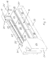
- FIG. 1 shows part of a window frame, namely the lower part of a casement with a lower one horizontal frame spar or frame profile bar 20. On this connect vertical connecting bars 24. The cross section of the left connecting bar 24 leaves that adjacent to the rebate Recognize the profile, especially the overlap inside the window 24 '. A fixed to the window frame Frame, which together with the sash frame the rebate has not been shown for simplification.
- the fan element 10 With the lower horizontal frame profile bar 20 is a Fan element 10 assembled.
- the fan element 10 is shown schematically and consists of a frame spar parallel Profile bar 50, at the ends of extension pieces or connect end caps 25.
- the profile rod 50 has one in Fig.1 not visible air passage, its air inlet is optically covered by a cap 99. Accordingly the end caps 25 also have corresponding optical cover caps 99 on.
- the casement of a window takes between its Holmen 24 or the frame profile bar 20 on a glazing and accordingly both the frame profile bar 20 and the connecting bars 24 adapted for glass reception.
- the connecting rail profile 24 ' has a rollover 24' 'against which it does not glazing shown, for example an insulating glass pane, can be used across the frame level.
- a Sealing takes place with an elastic, not shown Sealing strip, which is held in a sealing strip groove 17 is anchored.
- a glazing bead retaining groove 16 is used for anchoring a glazing bead, not shown, that the glazing supports towards the inside of the room.
- the fan element 10 is installed in the casement can be, it must be adapted accordingly on the side of the spar. It must, for example, on the glazing bead retaining be lockable. In addition, it must be on the glass side be designed so that it can accommodate the glazing. To for this purpose it is designed in the same way as the connecting bar profile 24 'or as the profile of the frame profile bar, not shown 20.
- the profile rod 50 and the end caps 25 have So a rollover 50 'or 25' and the profiles shown in the rest, for example glazing bead retaining grooves 50 '' or 25 ''.
- the Profile bar 50 on the frame spar side and glass side a window system specific Has rod profile, namely a glass Glass system profile and the frame system profile on the frame side adapted counter profile.
- the glass side is above all a system-compatible one Glazing bead retainer 16 of importance, in one Anchored glass retaining bar of the window system is. So with different thicknesses of glazing the same profile bar with different, on the glass thicknesses matched glass retaining strips and / or glass seals. This is independent of the previously described embodiments for all ventilation systems with door or window system specific Member profiles of importance.
- the profile bar 50 each has a rebate forming Profile, the end caps 25 on their to the rod 50th vertical end faces either to the longitudinal profile of the Connection bars 24 or to the longitudinal profile of the vertical Frame spars are adapted.
- the profile bar on the frame side and glass side or a door or window system specific to the neighboring frame Has rod profile so that it in the manufacturer Window systems can be applied easily.
- All profile bars 50 have an air passage 10 '' is similar to that shown in Figure 2a. Basically heard for this purpose an air inlet 30 in the outer wall 53 of the profile bar 50 and an air outlet 31 in an inside wall of this Profiles.
- the profile rod 50 is according to Fig. 2a, 2b as a hollow chamber rod trained, the two facing part-circular Bearing sections 86 for a shut-off body 51 having.
- the shut-off body 51 is circular and just as long, like the profile bar 50. It is stored with its outer circumference the bearing portions 86, diametrically opposite each other longitudinal sealing strips 100 available that allow air to pass through a clearance 101 prevent between the profile rod 50 and the shut-off body 51.
- the shut-off body 51 has distributed over its length arranged ventilation slots 88 that flow through Allow air if they are aligned according to Fig.2a and thus a flow connection between the air inlet 30 and the air outlet 31.
- sealing tabs 102 get into the in Fig.2b shown system on the profile bar 50, in which they Block off air access to ventilation slots 80. Accordingly are also the gaps 101 through the sealing strips 100 and the sealing tabs 102 each double sealed. An air flow across the fan element 10 is excluded.
- the air inlet 30 are hollow chambers 89 of the shut-off body 51 adjacent, so that there are good sound and thermal insulation values of the entire ventilation system.
- FIGS shown adjusting member 80 An adjustment of the shut-off body 51 either in the 2a shown in the open position or in the Fig.2b
- the blocking position shown takes place with the one shown in FIGS shown adjusting member 80.
- the adjusting member 80 is in an end cap 25 housed the same according to Figure 1 Has outer contour, like the profile bar 50.
- Fig.2d are also Hollow chambers to some extent corresponding to those of the profile bar 50 continued, but not through the end cap 25.
- the Rack and pinion slide 81 is parallel to the frame plane and at the same time arranged transversely to the shut-off body 51.
- 3a, 3b show a cross section of a profile bar 50, which is very similar to that of Figures 2a, 2b.
- Partial circular Bearing sections of the profile bar 50 support one as a hollow profile bar 51 '' formed shut-off body 51. This has one circular cross section, in the air delivery recesses 90 are incorporated.
- the hollow profile rod is close to its circumference 51 '' with hollow chambers 89, which over the Length of the bar 51 '' at least distributed ventilation slots 88 have on a partial circumference of the rod 51 ′′.
- the hollow section bar 51 '' is rotationally positive with a drive shaft 103 connected, which at its end is arranged in an end cap, not shown gear that bears as a toothed part acts and with a motor-driven toothing opposite is engaged.
- This intervention can be direct or via an intermediate gear, so that the rod 51 '' is rotatable or rotatable.
- the rod 51 '' If the rod 51 '' is rotated, it is possible to remove air from the Air inlet 30 through the air outlet 31 in the direction of Promote arrows.
- the amount of air delivered is dependent on the speed of rotation of the engine depending on all control options the engine technology can be used to metered amount of air conveyed. For example, it is possible perform a forced ventilation by the hollow section rod 51 '' is rotated periodically. This can ensure be that the space to be ventilated the predetermined Air volume is supplied. At the same time it is possible to provide evidence of this by the rotation period of the hollow profile rod 51 '' is documented.
- the hollow profile rod 51 '' is designed so that it is a Air flow between air inlet 30 and air outlet 31 also then allows if it is not rotated. For this are in the Near its outer circumference, ventilation slots 88 around shaft 103 arranged around that allow air to pass when there are differences in air pressure allow on both sides of the profile bar 50. The prerequisite for this is that shown in Fig.3a Positioning of the hollow profile rod 51 ''. If this is in accordance with Fig.3b positioned, it completely blocks the passage of air from. It is similar to the above-described embodiment a multi-chamber seal, so that good sound and thermal insulation values can be achieved.
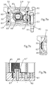
- Fig.4a to 4c show a profile rod 50 and an end cap 25 for storage of an adjusting member 80, which is the displacement of a one-piece Hollow chamber rods 51 '' 'are used.
- the profile bar 50 has inner walls 95, each of the inlet 30 to the outlet 31 out expand in a wedge shape. These wedge-shaped walls 95 are also sealing surfaces in cooperation with the Hollow chamber rod 51 '' ', of the same wedge-shaped outer circumference having. Wedge-shaped outer peripheral surfaces 104 are kept parallel to the walls 95.
- Hollow chamber rod 51 '' ' made of plastic multi-chambered and has a circular recess, in which a correspondingly circular stiffening rod 96 is installed is.
- the ends of the stiffening rod 96 are with Square projections 105 provided with an adjusting member 80 are rotationally positive. That is through an appropriate Square recess 106 in a gear 87 according to FIG. 4 shown.
- This gear 87 is thus one with the shut-off body 51 adjustable toothing part and is by one operator-side gear opposite in one direction of adjustment driven.
- the drive is either in the direction of adjustment 91 so that the rod 51 '' 'from the stiffening rod 96 is pressed into the shut-off position shown in FIG and an airtight complete seal of the air inlet 30 he follows.
- the outlet 31 is released and there may be air between the walls 95 and the outer peripheral surfaces 104 flow to outlet 31, from which the air into the interior reached.
- the gear 87 is adjusted or rotated for example, with a gear 83 designed as an adjusting gear operator-side opposite teeth. This is about one Intermediate wheel 82 and an intermediate slide 107 in adjustment engagement with the gear 87, which is also in mesh is located with a toothed strip 108 fixed to the end cap.
- the between this bar 108 and the intermediate slide 107 aligned held gear 87 is adjusted by half Adjustment speed of the intermediate slide 107, if this from the setting gear 83 via the intermediate gear 82 either in the first adjustment direction 91 or in the second adjustment direction 93 is moved. If the setting gear 83 in Turned clockwise, the gear is shifted 87 to the left, counterclockwise when turned right. As a result of the translation, a very sensitive Setting can be made.
- a shut-off body 51 designed as a two-part hollow chamber rod 51 IV is shown in cross section. It is located in a profile rod 50, the cross section of which is similar or identical to that of the rod 50 in FIGS. 4a, 4b.
- the two rod parts 94 are each triangular and designed as hollow chamber profiles. Each rod part 94 has a longitudinally grooved contact surface 104 with which it is held and adjusted on the wall 95 of the rod 50. With an adjustment in the first adjustment direction 91, the rod parts 94 move into the position shown in FIG. 5 and with adjustment in the second adjustment direction 93 they reach the position shown in FIG. 5b. According to FIG. 5a, the rod parts 94 completely block the air passage and, according to FIG. 5b, they release it.
- FIGS. 6a, 6b show in particular the formation of a Adjustment member 80 shown that for an adjustment of a Shut-off body 51 already shown in the main application suitable is.
- This shut-off body 51 is an insulating oval-cylindrical Hollow section rod, which most of the Air passage 10 '' available cross section of the Profile bars 50 occupies.
- On the cylindrical outer circumference of the shut-off body 51 are radially projecting sealing tabs 60 available, which is also along the entire length of the shut-off body 51 go through. They protrude in the direction of the corners, that of a longitudinal wall 52 and a transverse wall 53 of the rod 50 are formed.
- the two sealing tabs on the air intake side 60 are able to close the air inlet 30 when the Shut-off body 51 moved to the left in the illustration is.
- the two sealing tabs on the right in Fig 60 abutting sealing strips 59 of the rod. Becomes the shut-off body 51 is shifted to the right to shut off, the right sealing tabs 60 seal the air outlet 31, if so desired.
- the leadership of the shut-off body 51 within the profile bar 50 takes place with a toothing part 97 on the upper one Sealing strip 59.
- the toothed part 97 is with the shut-off body 51 fixedly connected and even by one Gear 87 adjustable, which is arranged stationary. It will driven by an intermediate gear 82 with a rack slide 81.
- the gear wheel adjusts the shut-off body 51 either in the shut-off position or in the Open position.
- the rack slide 81 also kick an adjusting gear.
- the idler gear 82 formed correspondingly smaller.
- the special feature is for the embodiment described above there is a stiffening rod 96.
- This extends within the blocking body 51 from one End of the profile bar to its other end and is in it rotatable.
- the hexagonal profile grips at the ends Stiffening rod 96 rotated in a gear 87 on.
- an adjusting element 80 adjustment forces exerted on a gear 87 from one end of the stiffening rod 96 on its other end independently transferred from the shut-off body 51, where it is on the shut-off body 51 act in the sense of an adjustment.
- the shut-off body 51 is therefore driven at both ends in the sense of an adjustment, but with the stiffening rod 96 only on one its ends are acted upon by the adjusting member.
- shut-off bodies 51 which are designed as two-part hollow-chamber rods 51 IV .
- the cross section of each rod part 85 is approximately U-shaped and the U-legs of the rod parts 85 face each other and interact telescopically.
- Each rod part 85 carries at its end facing an air outlet 31 or an air inlet 30 sealing tabs 60 with which a seal can be achieved.
- the shut-off position is such that the rod parts 85 have moved apart as far as possible and bear with their sealing tabs 60 on the transverse walls 53 of the profile rod 50. In the shut-off position, double-sided sealing takes place, that is to say both near the air inlet 30 and near the air outlet 31.
- the adjustment element 80 required for moving the rod parts 85 is designed similarly to that of FIGS. 6a, 6b.
- An intermediate gear 82 is driven with a rack and pinion slide 81, which in turn acts on a gear 87.
- the toothed wheel 87 is a double toothed wheel with a pinion 87 ′ with a diameter which engages between the rod parts 85.
- there is a toothed rack 98 which can be adjusted with the shut-off body 51 or its rod part 85 and into which the pinion 87 'engages.
- the racks 98 can be stiffening rods 96 which run over the entire length of the hollow rod 51 IV ', so that a pinion 87' can also be present in an end cap at the other end of the fan element in order to make the adjusting forces acting between the parts 85 more uniform Distribute pressure forces on the sealing outer peripheries of the shut-off body 51.
- FIG. 7c shows a shut-off body 51 with a further two-part hollow chamber rod 51 IV , not shown, the U-shaped rod part 85 of which has a flat bottom adjacent to the air inlet 30, on which a sealing bead 60 'is present.
- This sealing bead or an elastic sealing lip which is therefore only attached to the bar part 85 at one edge, reliably seals the air inlet 30.
Landscapes
- Engineering & Computer Science (AREA)
- Civil Engineering (AREA)
- Structural Engineering (AREA)
- Air-Conditioning For Vehicles (AREA)
- Air-Flow Control Members (AREA)
Applications Claiming Priority (2)
| Application Number | Priority Date | Filing Date | Title |
|---|---|---|---|
| DE19841296 | 1998-09-09 | ||
| DE19841296A DE19841296A1 (de) | 1998-06-25 | 1998-09-09 | Lüftungssystem an Tür-oder Fensterrahmen |
Publications (2)
| Publication Number | Publication Date |
|---|---|
| EP0994233A2 true EP0994233A2 (fr) | 2000-04-19 |
| EP0994233A3 EP0994233A3 (fr) | 2002-02-06 |
Family
ID=7880429
Family Applications (1)
| Application Number | Title | Priority Date | Filing Date |
|---|---|---|---|
| EP99115991A Withdrawn EP0994233A3 (fr) | 1998-09-09 | 1999-08-14 | Système de ventilation à cadres de portes ou fenêtres |
Country Status (1)
| Country | Link |
|---|---|
| EP (1) | EP0994233A3 (fr) |
Cited By (2)
| Publication number | Priority date | Publication date | Assignee | Title |
|---|---|---|---|---|
| DE202006017606U1 (de) * | 2006-11-16 | 2008-03-27 | Rademacher, Wilhelm | Türanordnung |
| ITBO20100050A1 (it) * | 2010-01-27 | 2011-07-28 | Gsg Int Spa | Anta per serramenti con dispositivo di ventilazione. |
Family Cites Families (5)
| Publication number | Priority date | Publication date | Assignee | Title |
|---|---|---|---|---|
| CH499005A (de) * | 1968-10-14 | 1970-11-15 | Gustaf Carlson John | Ventilationsvorrichtung an Fenstern oder Türen |
| DE2919682A1 (de) * | 1979-05-16 | 1980-11-20 | Siegenia Frank Kg | Lueftungsvorrichtung fuer den einbau in fenster und/oder in andere wandoeffnungen von gebaeuden |
| CH668310A5 (fr) * | 1986-07-22 | 1988-12-15 | Hubert De Schrijver | Dispositif d'aerage. |
| EP0291540A1 (fr) * | 1987-05-16 | 1988-11-23 | Ernst Josef Meeth | Ferrure pour fenêtre à battant |
| NL9200230A (nl) * | 1992-02-07 | 1993-09-01 | Compri Aluminium | Ventilatierooster. |
-
1999
- 1999-08-14 EP EP99115991A patent/EP0994233A3/fr not_active Withdrawn
Cited By (2)
| Publication number | Priority date | Publication date | Assignee | Title |
|---|---|---|---|---|
| DE202006017606U1 (de) * | 2006-11-16 | 2008-03-27 | Rademacher, Wilhelm | Türanordnung |
| ITBO20100050A1 (it) * | 2010-01-27 | 2011-07-28 | Gsg Int Spa | Anta per serramenti con dispositivo di ventilazione. |
Also Published As
| Publication number | Publication date |
|---|---|
| EP0994233A3 (fr) | 2002-02-06 |
Similar Documents
| Publication | Publication Date | Title |
|---|---|---|
| EP0021164B1 (fr) | Dispositif de ventilation à insérer dans des châssis de fenêtre ou de porte | |
| EP0141805A2 (fr) | Volet à rouleau | |
| EP1063384A2 (fr) | Dispositif de ventilation | |
| CH634630A5 (en) | Retractable and extendible covering device in the manner of a roller shutter | |
| DE19634391A1 (de) | Bodenverankerung für Flügel einer ortsveränderbaren Schiebeflügelwand aus Isolierglas | |
| EP1936295B1 (fr) | Installation de fermeture d'une ouverture de local | |
| DE3317341C2 (de) | Kraftfahrzeugtür | |
| EP1462594B2 (fr) | Mécanisme d'engrenage, en particulier mécanisme d'engrenage encastré pour fenêtre ou similaire | |
| EP1128018B1 (fr) | Fenêtre à lamelles | |
| EP2933412A1 (fr) | Entraînement de porte rotative | |
| DE2703207C3 (de) | Lüftungsvorrichtung für Räume | |
| EP0563550B1 (fr) | Ferrure pour fenêtre ou porte pivotante autour son axe central | |
| WO2000052288A1 (fr) | Fenetre ou porte | |
| DE2616422C3 (de) | Fenster oder Tür mit einem feststehenden Rahmen aus zwei rahmenförmigen, einen Zwischenraum einschließenden Teilen | |
| DE19841296A1 (de) | Lüftungssystem an Tür-oder Fensterrahmen | |
| EP3913171B1 (fr) | Entraînement de verrouillage et/ou de positionnement pour une fenêtre, une porte ou similaire | |
| EP1707726B1 (fr) | Dispositif pour l'ouverture et la fermeture d'une fenêtre ou porte montée coulissante sur un cadre | |
| EP2514909A2 (fr) | Fenêtre à lamelles | |
| DE1266173B (de) | Getriebe eines Treibstangenbeschlages fuer Fenster, Tueren od. dgl., insbesondere fuer Kipp-Schwenkfluegel-Fenster | |
| EP0668427B1 (fr) | Ferrure pour portes, fenêtres ou analoques | |
| DE2030746A1 (de) | Fensterrahmen aus Kunststoff mit einer Verstärkungseinlage, welche zugleich Zentralverschluß ist | |
| AT394608B (de) | Drehkipp-, kipp-, klapp- oder drehfenster oder -tuer | |
| EP0935047B1 (fr) | Système de ventilation pour châssis de porte ou de fenêtre | |
| DE3425810C2 (fr) | ||
| DE1242121B (de) | Fuer Fenster, Tueren od. dgl. bestimmter Zentralverschluss mit durch Eckumlenkungen miteinander verbundenen Verschluss- und Abdichtschienen |
Legal Events
| Date | Code | Title | Description |
|---|---|---|---|
| PUAI | Public reference made under article 153(3) epc to a published international application that has entered the european phase |
Free format text: ORIGINAL CODE: 0009012 |
|
| AK | Designated contracting states |
Kind code of ref document: A2 Designated state(s): AT BE CH CY DE DK ES FI FR GB GR IE IT LI LU MC NL PT SE Kind code of ref document: A2 Designated state(s): AT CH DE LI |
|
| AX | Request for extension of the european patent |
Free format text: AL;LT;LV;MK;RO;SI |
|
| PUAL | Search report despatched |
Free format text: ORIGINAL CODE: 0009013 |
|
| AK | Designated contracting states |
Kind code of ref document: A3 Designated state(s): AT BE CH CY DE DK ES FI FR GB GR IE IT LI LU MC NL PT SE |
|
| AX | Request for extension of the european patent |
Free format text: AL;LT;LV;MK;RO;SI |
|
| RIC1 | Information provided on ipc code assigned before grant |
Free format text: 7E 06B 7/02 A, 7E 06B 7/10 B |
|
| AKX | Designation fees paid |
Free format text: AT CH DE LI |
|
| STAA | Information on the status of an ep patent application or granted ep patent |
Free format text: STATUS: THE APPLICATION IS DEEMED TO BE WITHDRAWN |
|
| 18D | Application deemed to be withdrawn |
Effective date: 20020807 |