EP0994255B1 - Système de pompage de carburant à haute pression - Google Patents
Système de pompage de carburant à haute pression Download PDFInfo
- Publication number
- EP0994255B1 EP0994255B1 EP99103956A EP99103956A EP0994255B1 EP 0994255 B1 EP0994255 B1 EP 0994255B1 EP 99103956 A EP99103956 A EP 99103956A EP 99103956 A EP99103956 A EP 99103956A EP 0994255 B1 EP0994255 B1 EP 0994255B1
- Authority
- EP
- European Patent Office
- Prior art keywords
- check valve
- high pressure
- pressure fuel
- fuel
- pumping apparatus
- Prior art date
- Legal status (The legal status is an assumption and is not a legal conclusion. Google has not performed a legal analysis and makes no representation as to the accuracy of the status listed.)
- Expired - Lifetime
Links
Images



Classifications
-
- F—MECHANICAL ENGINEERING; LIGHTING; HEATING; WEAPONS; BLASTING
- F04—POSITIVE - DISPLACEMENT MACHINES FOR LIQUIDS; PUMPS FOR LIQUIDS OR ELASTIC FLUIDS
- F04B—POSITIVE-DISPLACEMENT MACHINES FOR LIQUIDS; PUMPS
- F04B53/00—Component parts, details or accessories not provided for in, or of interest apart from, groups F04B1/00 - F04B23/00 or F04B39/00 - F04B47/00
- F04B53/04—Draining
-
- F—MECHANICAL ENGINEERING; LIGHTING; HEATING; WEAPONS; BLASTING
- F02—COMBUSTION ENGINES; HOT-GAS OR COMBUSTION-PRODUCT ENGINE PLANTS
- F02M—SUPPLYING COMBUSTION ENGINES IN GENERAL WITH COMBUSTIBLE MIXTURES OR CONSTITUENTS THEREOF
- F02M59/00—Pumps specially adapted for fuel-injection and not provided for in groups F02M39/00 -F02M57/00, e.g. rotary cylinder-block type of pumps
- F02M59/44—Details, components parts, or accessories not provided for in, or of interest apart from, the apparatus of groups F02M59/02 - F02M59/42; Pumps having transducers, e.g. to measure displacement of pump rack or piston
- F02M59/46—Valves
-
- F—MECHANICAL ENGINEERING; LIGHTING; HEATING; WEAPONS; BLASTING
- F02—COMBUSTION ENGINES; HOT-GAS OR COMBUSTION-PRODUCT ENGINE PLANTS
- F02M—SUPPLYING COMBUSTION ENGINES IN GENERAL WITH COMBUSTIBLE MIXTURES OR CONSTITUENTS THEREOF
- F02M55/00—Fuel-injection apparatus characterised by their fuel conduits or their venting means; Arrangements of conduits between fuel tank and pump F02M37/00
- F02M55/004—Joints; Sealings
-
- F—MECHANICAL ENGINEERING; LIGHTING; HEATING; WEAPONS; BLASTING
- F02—COMBUSTION ENGINES; HOT-GAS OR COMBUSTION-PRODUCT ENGINE PLANTS
- F02M—SUPPLYING COMBUSTION ENGINES IN GENERAL WITH COMBUSTIBLE MIXTURES OR CONSTITUENTS THEREOF
- F02M59/00—Pumps specially adapted for fuel-injection and not provided for in groups F02M39/00 -F02M57/00, e.g. rotary cylinder-block type of pumps
- F02M59/44—Details, components parts, or accessories not provided for in, or of interest apart from, the apparatus of groups F02M59/02 - F02M59/42; Pumps having transducers, e.g. to measure displacement of pump rack or piston
-
- F—MECHANICAL ENGINEERING; LIGHTING; HEATING; WEAPONS; BLASTING
- F04—POSITIVE - DISPLACEMENT MACHINES FOR LIQUIDS; PUMPS FOR LIQUIDS OR ELASTIC FLUIDS
- F04B—POSITIVE-DISPLACEMENT MACHINES FOR LIQUIDS; PUMPS
- F04B49/00—Control, e.g. of pump delivery, or pump pressure of, or safety measures for, machines, pumps, or pumping installations, not otherwise provided for, or of interest apart from, groups F04B1/00 - F04B47/00
- F04B49/08—Regulating by delivery pressure
-
- F—MECHANICAL ENGINEERING; LIGHTING; HEATING; WEAPONS; BLASTING
- F04—POSITIVE - DISPLACEMENT MACHINES FOR LIQUIDS; PUMPS FOR LIQUIDS OR ELASTIC FLUIDS
- F04B—POSITIVE-DISPLACEMENT MACHINES FOR LIQUIDS; PUMPS
- F04B2205/00—Fluid parameters
- F04B2205/05—Pressure after the pump outlet
Definitions
- first check valve and the second check valve may be integrally mounted in a casing for housing the sleeve.
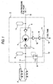
- Fig. 1 is a block diagram showing the arrangement of a high pressure fuel pumping apparatus according to an embodiment of the present invention.
- Fig. 2 is a sectional view of the details of the high pressure fuel pumping apparatus according to the embodiment of the present invention.
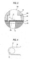
- Fig. 3 is an enlarged sectional view of the main part viewed by an arrow A in Fig. 2.
- Fig. 4 is an enlarged plan view of the main part of the arrow A in Fig. 2.
- a second check valve 18 with good sealing property and of a ball type is arranged downstream in the drain passage 12 between a merging point 14 and the fuel sealing metallic bellows of the high pressure fuel pump 5.
- the piston 21 is reciprocated by rotation of the cam 19 through the tappet 20. While the piston 21 descends, fuel flows from the low pressure fuel passage 10 into the pumping chamber through the fuel inhalation passage 34a, inhalation opening 29a of the plate B 29, inhalation valve of the lead valve 30 and inhalation hole 28a of the plate A 28.
- the high pressure fuel regulator 8 can be constituted as a body separated from the casing 3 of the high pressure fuel pump 5.
- the first check valve is constructed from the lead type of check valve 17 with good response and the second check valve is constructed from the ball type of check valve 18 having good sealing property.
- these first and second check valves may be constructed from the lead type of check valves, respectively, or alternatively by ball type of check valves, respectively.
- two check valves are arranged on the drain passage between the fuel sealing metallic bellows 26 and the merging point 14 so that the fuel flowing backward toward the metallic bellows 26 through the drain passage 13 of the high pressure fuel regulator 8 and merging point 14 can be effectively sealed.
- the first check valve and the second check valve are integrally mounted in a casing for housing the sleeve.
- the construction of each check valve can be simplified and the passage of communicating these check valves can be shortened.
Landscapes
- Engineering & Computer Science (AREA)
- Mechanical Engineering (AREA)
- General Engineering & Computer Science (AREA)
- Chemical & Material Sciences (AREA)
- Combustion & Propulsion (AREA)
- Fuel-Injection Apparatus (AREA)
- Details Of Reciprocating Pumps (AREA)
Claims (7)
- Appareil de pompage de combustible à haute pression (3) comprenant :caractérisé en ce qu'il comprendun soufflet d'étanchéité de combustible (26) empêchant le combustible s'écoulant par un espacement entre une chemise (24) et un piston (21) se déplaçant alternativement dans celle-ci, de fuir à l'extérieur ;un premier passage de drain (12) pour le combustible s'écoulant de l'intérieur dudit soufflet (26) ;un second passage de drain (13) pour un régulateur de combustible à haute pression (8) régulant la pression de combustible déchargé de l'appareil de pompage de combustible à haute pression (3) à une valeur prescrite, ledit premier et ledit second passages de drain (12, 13) étant fusionnés à un point de fusion (14) ;un premier clapet de non-retour (17) situé en amont dans le premier passage de drain (12) entre ledit point de fusion (14) et ledit soufflet (26) ;
un second clapet de non-retour (18) situé en aval du premier clapet de non-retour (17) dans ledit premier passage de drain (12). - Appareil de pompage de combustible à haute pression (3) selon la revendication 1, dans lequel ledit premier clapet de non-retour (17) est constitué d'un clapet de non-retour ayant une bonne réponse et le second clapet de non-retour (18) est constitué d'un autre clapet de non-retour ayant une bonne propriété d'étanchéité.
- Appareil de pompage de combustible à haute pression (3) selon la revendication 2, dans lequel ledit premier clapet de non-retour (17) est constitué d'un clapet de non-retour de type directionnel et ledit second clapet de non-retour (18) est constitué d'un clapet de non-retour de type à bille.
- Appareil de pompage de combustible à haute pression (3) selon l'une quelconque des revendications 1 à 3, dans lequel ledit premier clapet de non-retour (17) et ledit second clapet de non-retour (18) sont montés de manière intégrale dans un boítier (34) pour loger ladite chemise (24).
- Appareil de pompage de combustible à haute pression (3) selon l'une quelconque des revendications 1 à 4, dans lequel ledit premier clapet de non-retour (17) est formé de manière intégrale avec un clapet directionnel (30) pour aspiration et décharge dans une chambre de pompage formée par ladite chemise (24) et ledit piston (21).
- Appareil de pompage de combustible à haute pression (3) selon l'une quelconque des revendications 1 à 5, comprenant ledit régulateur à haute pression (8) monté de manière intégrale.
- Appareil de pompage de combustible à haute pression (3) selon l'une quelconque des revendications 1 à 6, dans lequel ledit soufflet (23) est fait d'un matériau métallique.
Applications Claiming Priority (2)
| Application Number | Priority Date | Filing Date | Title |
|---|---|---|---|
| JP29200798A JP3633314B2 (ja) | 1998-10-14 | 1998-10-14 | 高圧燃料ポンプ装置 |
| JP29200798 | 1998-10-14 |
Publications (2)
| Publication Number | Publication Date |
|---|---|
| EP0994255A1 EP0994255A1 (fr) | 2000-04-19 |
| EP0994255B1 true EP0994255B1 (fr) | 2004-05-19 |
Family
ID=17776330
Family Applications (1)
| Application Number | Title | Priority Date | Filing Date |
|---|---|---|---|
| EP99103956A Expired - Lifetime EP0994255B1 (fr) | 1998-10-14 | 1999-03-09 | Système de pompage de carburant à haute pression |
Country Status (6)
| Country | Link |
|---|---|
| US (1) | US6131549A (fr) |
| EP (1) | EP0994255B1 (fr) |
| JP (1) | JP3633314B2 (fr) |
| KR (1) | KR100339470B1 (fr) |
| DE (1) | DE69917407T2 (fr) |
| TW (1) | TW387974B (fr) |
Families Citing this family (15)
| Publication number | Priority date | Publication date | Assignee | Title |
|---|---|---|---|---|
| GB9900070D0 (en) * | 1999-01-05 | 1999-02-24 | Lucas Franc | Control method |
| JP2001055961A (ja) * | 1999-08-11 | 2001-02-27 | Mitsubishi Electric Corp | 高圧燃料供給装置 |
| JP2001059467A (ja) * | 1999-08-20 | 2001-03-06 | Mitsubishi Electric Corp | 高圧燃料ポンプ |
| EP1312793B1 (fr) * | 2000-08-24 | 2010-12-22 | Mitsubishi Denki Kabushiki Kaisha | Dispositif d'alimentation en carburant haute pression |
| JP3924716B2 (ja) * | 2002-04-10 | 2007-06-06 | ボッシュ株式会社 | 蓄圧式燃料噴射システム |
| JP3944413B2 (ja) * | 2002-05-24 | 2007-07-11 | 株式会社日立製作所 | 高圧燃料供給ポンプ |
| JP2008057451A (ja) * | 2006-08-31 | 2008-03-13 | Hitachi Ltd | 高圧燃料供給ポンプ |
| DE102008043217A1 (de) * | 2008-10-28 | 2010-04-29 | Robert Bosch Gmbh | Kraftstoff-Hochdruckpumpe für eine Brennkraftmaschine |
| EP2589807A1 (fr) * | 2011-11-07 | 2013-05-08 | hofer mechatronik GmbH | Pompe à soufflet à plis |
| US20130312706A1 (en) * | 2012-05-23 | 2013-11-28 | Christopher J. Salvador | Fuel system having flow-disruption reducer |
| DE102013212047A1 (de) * | 2013-06-25 | 2015-01-08 | Robert Bosch Gmbh | Pumpvorrichtung, insbesondere Kraftstoffhochdruckpumpvorrichtung für eine Kraftstoffeinspritzeinrichtung |
| CN104956069B (zh) * | 2013-10-14 | 2018-01-26 | 大陆汽车有限公司 | 高压泵 |
| JP6040912B2 (ja) * | 2013-11-12 | 2016-12-07 | 株式会社デンソー | 高圧ポンプ |
| JP6934519B2 (ja) | 2017-07-14 | 2021-09-15 | 日立Astemo株式会社 | 高圧燃料ポンプ |
| DE102018220942A1 (de) * | 2018-12-04 | 2020-06-04 | Robert Bosch Gmbh | Pumpe, insbesondere Kraftstoffhochdruckpumpe für eine Kraftstoffeinspritzeinrichtung einer Brennkraftmaschine |
Family Cites Families (7)
| Publication number | Priority date | Publication date | Assignee | Title |
|---|---|---|---|---|
| DE3140742A1 (de) * | 1981-10-14 | 1983-04-28 | Mannesmann Rexroth GmbH, 8770 Lohr | "pumpe, insbesondere zum foerdern einer giftigen fluesigkeit" |
| US4869219A (en) * | 1986-07-14 | 1989-09-26 | Cummins Engine Company, Inc. | Dual spring air fuel control for the PT fuel system |
| JPH0712029A (ja) * | 1993-06-24 | 1995-01-17 | Mitsubishi Electric Corp | 高圧燃料ポンプ |
| JP3760486B2 (ja) * | 1995-08-30 | 2006-03-29 | 日産自動車株式会社 | 燃料ポンプ |
| US5731515A (en) * | 1995-11-30 | 1998-03-24 | Mitsubishi Denki Kabushiki Kaisha | High-pressure pump unit and test method therefor |
| JPH10176625A (ja) * | 1996-12-19 | 1998-06-30 | Unisia Jecs Corp | プランジャポンプ |
| JP3552464B2 (ja) * | 1997-05-30 | 2004-08-11 | 三菱電機株式会社 | 機関の燃料供給装置 |
-
1998
- 1998-10-14 JP JP29200798A patent/JP3633314B2/ja not_active Expired - Fee Related
-
1999
- 1999-02-16 US US09/249,784 patent/US6131549A/en not_active Expired - Lifetime
- 1999-02-19 TW TW088102408A patent/TW387974B/zh not_active IP Right Cessation
- 1999-03-09 EP EP99103956A patent/EP0994255B1/fr not_active Expired - Lifetime
- 1999-03-09 DE DE69917407T patent/DE69917407T2/de not_active Expired - Lifetime
- 1999-05-24 KR KR1019990018689A patent/KR100339470B1/ko not_active Expired - Fee Related
Also Published As
| Publication number | Publication date |
|---|---|
| DE69917407T2 (de) | 2005-06-02 |
| TW387974B (en) | 2000-04-21 |
| KR100339470B1 (ko) | 2002-06-05 |
| KR20000028578A (ko) | 2000-05-25 |
| JP3633314B2 (ja) | 2005-03-30 |
| JP2000120506A (ja) | 2000-04-25 |
| EP0994255A1 (fr) | 2000-04-19 |
| US6131549A (en) | 2000-10-17 |
| DE69917407D1 (de) | 2004-06-24 |
Similar Documents
| Publication | Publication Date | Title |
|---|---|---|
| EP0994255B1 (fr) | Système de pompage de carburant à haute pression | |
| KR100331758B1 (ko) | 통내분사용고압연료펌프 | |
| US5265804A (en) | Electrically controlled fuel injector unit | |
| EP0976925B1 (fr) | Assemblage d'une pompe à carburant à haute pression | |
| JP3830524B2 (ja) | 内燃機関用の燃料噴射装置 | |
| US7377753B2 (en) | Fuel supply pump | |
| US20110209687A1 (en) | High-pressure fuel pump for an internal combustion engine | |
| US8371268B2 (en) | Safety valve and high-pressure pump comprising said safety valve | |
| US20140255219A1 (en) | Valve Configuration For Single Piston Fuel Pump | |
| US9422897B2 (en) | Fuel system for an internal combustion engine | |
| US6581577B1 (en) | Pump arrangement for providing fuel at high pressure | |
| CN100362229C (zh) | 机动二轮车的燃料供给装置 | |
| US6959694B2 (en) | Fuel injection system for an internal combustion engine | |
| KR20240007764A (ko) | 입구 밸브 조립체를 갖는 연료 펌프 | |
| JP2922488B1 (ja) | 高圧燃料ポンプのフィード圧脈動低減装置 | |
| JP2001059467A (ja) | 高圧燃料ポンプ | |
| EP1336752A3 (fr) | Système d'injection de carburant | |
| JP3708702B2 (ja) | 高圧燃料ポンプのフィード圧脈動低減装置 | |
| JP2017048782A (ja) | 燃料供給装置 | |
| JPH11351089A (ja) | 燃料供給装置 | |
| JP4840376B2 (ja) | 燃料供給装置 | |
| JPS6133253Y2 (fr) | ||
| CN102052213A (zh) | 燃料供给装置 | |
| JPS58148268A (ja) | 燃料噴射ポンプ | |
| JP2001182636A (ja) | メカ駆動式燃料ポンプを含む燃料系のベーパー排出構造 |
Legal Events
| Date | Code | Title | Description |
|---|---|---|---|
| PUAI | Public reference made under article 153(3) epc to a published international application that has entered the european phase |
Free format text: ORIGINAL CODE: 0009012 |
|
| AK | Designated contracting states |
Kind code of ref document: A1 Designated state(s): DE FR IT |
|
| AX | Request for extension of the european patent |
Free format text: AL;LT;LV;MK;RO;SI |
|
| 17P | Request for examination filed |
Effective date: 20000619 |
|
| AKX | Designation fees paid |
Free format text: DE FR IT |
|
| 17Q | First examination report despatched |
Effective date: 20030220 |
|
| GRAP | Despatch of communication of intention to grant a patent |
Free format text: ORIGINAL CODE: EPIDOSNIGR1 |
|
| GRAS | Grant fee paid |
Free format text: ORIGINAL CODE: EPIDOSNIGR3 |
|
| GRAA | (expected) grant |
Free format text: ORIGINAL CODE: 0009210 |
|
| AK | Designated contracting states |
Kind code of ref document: B1 Designated state(s): DE FR IT |
|
| REF | Corresponds to: |
Ref document number: 69917407 Country of ref document: DE Date of ref document: 20040624 Kind code of ref document: P |
|
| ET | Fr: translation filed | ||
| PLBE | No opposition filed within time limit |
Free format text: ORIGINAL CODE: 0009261 |
|
| STAA | Information on the status of an ep patent application or granted ep patent |
Free format text: STATUS: NO OPPOSITION FILED WITHIN TIME LIMIT |
|
| 26N | No opposition filed |
Effective date: 20050222 |
|
| PGFP | Annual fee paid to national office [announced via postgrant information from national office to epo] |
Ref country code: IT Payment date: 20090319 Year of fee payment: 11 |
|
| PGFP | Annual fee paid to national office [announced via postgrant information from national office to epo] |
Ref country code: FR Payment date: 20090316 Year of fee payment: 11 |
|
| REG | Reference to a national code |
Ref country code: FR Ref legal event code: ST Effective date: 20101130 |
|
| PG25 | Lapsed in a contracting state [announced via postgrant information from national office to epo] |
Ref country code: FR Free format text: LAPSE BECAUSE OF NON-PAYMENT OF DUE FEES Effective date: 20100331 |
|
| PG25 | Lapsed in a contracting state [announced via postgrant information from national office to epo] |
Ref country code: IT Free format text: LAPSE BECAUSE OF NON-PAYMENT OF DUE FEES Effective date: 20100309 |
|
| PGFP | Annual fee paid to national office [announced via postgrant information from national office to epo] |
Ref country code: DE Payment date: 20140417 Year of fee payment: 16 |
|
| REG | Reference to a national code |
Ref country code: DE Ref legal event code: R084 Ref document number: 69917407 Country of ref document: DE |
|
| REG | Reference to a national code |
Ref country code: DE Ref legal event code: R084 Ref document number: 69917407 Country of ref document: DE Effective date: 20141107 |
|
| REG | Reference to a national code |
Ref country code: DE Ref legal event code: R119 Ref document number: 69917407 Country of ref document: DE |
|
| PG25 | Lapsed in a contracting state [announced via postgrant information from national office to epo] |
Ref country code: DE Free format text: LAPSE BECAUSE OF NON-PAYMENT OF DUE FEES Effective date: 20151001 |