EP0994376A1 - Lentille oculaire multifocale avec une zone de correction pour la distance intermediaire - Google Patents
Lentille oculaire multifocale avec une zone de correction pour la distance intermediaire Download PDFInfo
- Publication number
- EP0994376A1 EP0994376A1 EP99308075A EP99308075A EP0994376A1 EP 0994376 A1 EP0994376 A1 EP 0994376A1 EP 99308075 A EP99308075 A EP 99308075A EP 99308075 A EP99308075 A EP 99308075A EP 0994376 A1 EP0994376 A1 EP 0994376A1
- Authority
- EP
- European Patent Office
- Prior art keywords
- vision correction
- optical power
- correction region
- distance
- distant
- Prior art date
- Legal status (The legal status is an assumption and is not a legal conclusion. Google has not performed a legal analysis and makes no representation as to the accuracy of the status listed.)
- Withdrawn
Links
- 230000004438 eyesight Effects 0.000 title claims abstract description 305
- 230000003287 optical effect Effects 0.000 claims abstract description 243
- 208000001491 myopia Diseases 0.000 claims abstract description 58
- 238000009826 distribution Methods 0.000 claims description 26
- 210000001508 eye Anatomy 0.000 description 18
- 230000004304 visual acuity Effects 0.000 description 15
- 210000001747 pupil Anatomy 0.000 description 11
- 230000000694 effects Effects 0.000 description 7
- 238000003384 imaging method Methods 0.000 description 7
- 230000007246 mechanism Effects 0.000 description 7
- 230000008859 change Effects 0.000 description 6
- 238000005520 cutting process Methods 0.000 description 6
- 230000000007 visual effect Effects 0.000 description 5
- 238000006073 displacement reaction Methods 0.000 description 4
- 238000000465 moulding Methods 0.000 description 4
- 210000004087 cornea Anatomy 0.000 description 3
- 230000007423 decrease Effects 0.000 description 3
- 230000003449 preventive effect Effects 0.000 description 3
- 238000003754 machining Methods 0.000 description 2
- 239000002243 precursor Substances 0.000 description 2
- 201000010041 presbyopia Diseases 0.000 description 2
- 230000004308 accommodation Effects 0.000 description 1
- 230000009471 action Effects 0.000 description 1
- 230000004075 alteration Effects 0.000 description 1
- 201000009310 astigmatism Diseases 0.000 description 1
- 210000004556 brain Anatomy 0.000 description 1
- 210000005252 bulbus oculi Anatomy 0.000 description 1
- 230000006866 deterioration Effects 0.000 description 1
- 230000002542 deteriorative effect Effects 0.000 description 1
- 230000005484 gravity Effects 0.000 description 1
- 230000004371 high visual acuity Effects 0.000 description 1
- 230000002209 hydrophobic effect Effects 0.000 description 1
- 239000000463 material Substances 0.000 description 1
- 238000000034 method Methods 0.000 description 1
- 230000004048 modification Effects 0.000 description 1
- 238000012986 modification Methods 0.000 description 1
- 229920003229 poly(methyl methacrylate) Polymers 0.000 description 1
- 239000004926 polymethyl methacrylate Substances 0.000 description 1
- 238000007493 shaping process Methods 0.000 description 1
- 230000007704 transition Effects 0.000 description 1
Images






Classifications
-
- G—PHYSICS
- G02—OPTICS
- G02C—SPECTACLES; SUNGLASSES OR GOGGLES INSOFAR AS THEY HAVE THE SAME FEATURES AS SPECTACLES; CONTACT LENSES
- G02C7/00—Optical parts
- G02C7/02—Lenses; Lens systems ; Methods of designing lenses
- G02C7/04—Contact lenses for the eyes
- G02C7/041—Contact lenses for the eyes bifocal; multifocal
- G02C7/044—Annular configuration, e.g. pupil tuned
-
- G—PHYSICS
- G02—OPTICS
- G02C—SPECTACLES; SUNGLASSES OR GOGGLES INSOFAR AS THEY HAVE THE SAME FEATURES AS SPECTACLES; CONTACT LENSES
- G02C7/00—Optical parts
- G02C7/02—Lenses; Lens systems ; Methods of designing lenses
- G02C7/04—Contact lenses for the eyes
- G02C7/041—Contact lenses for the eyes bifocal; multifocal
- G02C7/042—Simultaneous type
-
- G—PHYSICS
- G02—OPTICS
- G02C—SPECTACLES; SUNGLASSES OR GOGGLES INSOFAR AS THEY HAVE THE SAME FEATURES AS SPECTACLES; CONTACT LENSES
- G02C7/00—Optical parts
- G02C7/02—Lenses; Lens systems ; Methods of designing lenses
- G02C7/04—Contact lenses for the eyes
- G02C7/041—Contact lenses for the eyes bifocal; multifocal
- G02C7/043—Translating type
-
- G—PHYSICS
- G02—OPTICS
- G02C—SPECTACLES; SUNGLASSES OR GOGGLES INSOFAR AS THEY HAVE THE SAME FEATURES AS SPECTACLES; CONTACT LENSES
- G02C2202/00—Generic optical aspects applicable to one or more of the subgroups of G02C7/00
- G02C2202/04—Lenses comprising decentered structures
Definitions
- the present invention relates in general to an ocular lens such as a contact lens placed on an eyeball or an intraocular lens inserted within an eye. More particularly, the invention is concerned with a multifocal ocular lens having a plurality of vision correction regions with respective different values of optical or vision correction power.
- a multifocal ocular lens having a plurality of vision correction regions which provide respective different values of optical power.
- JP-A-63-95415 and JP-A-1-319729 disclose an alternating or translating vision type contact lens, wherein the vision correction regions with different values of optical power are selectively and alternatively used as needed in observing objects, with a shift of the visual axis of the lens user or wearer.
- US Pat. No. 4,580,882 and JP-A-2-217818 disclose a simultaneous vision type contact lens, wherein the vision correction regions are simultaneously used, and one of the vision correction regions through which a desired image is observed is selected by an action of the lens wearer's brain.
- a so-called bifocal ocular lens having two vision correction regions, i.e., a near vision correction region through which near objects are observed and a distant vision correction region through which distant objects are observed; and a multifocal ocular lens having such near and distant vision correction regions and at least one intermediate vision correction region which is interposed between those near and distant vision correction regions and which provides an optical power different from the optical powers of the near and distant vision correction regions.
- the multifocal ocular lens has at least three vision correction regions having respective different optical power values.
- the bifocal ocular lens having the two vision correction regions tends to suffer from a jump or overlapping of the image of an object which is located intermediate between near and distant objects. This is because the bifocal ocular lens has only two focal points which correspond to the respective near and distant vision correction regions. Further, the bifocal ocular lens has surface discontinuity at a junction of the near and distant vision correction regions, in other words, the two vision correction regions are not smoothly connected to each other at the junction therebetween, deteriorating a wearing comfort as felt by the lens user.
- each of the plurality of vision correction regions inevitably has a relatively small radial dimension, so that the optical power of the lens changes in steps in its radial direction, corresponding to the plurality of vision correction regions.
- the near and distant vision correction regions do not have sufficiently large surface areas, whereby the images to be obtained through these near and distant vision correction regions undesirably tend to be blurred.
- the multifocal ocular lens does not assure a high degree of visual acuity of the object located intermediate between the near and distant objects, so that the multifocal ocular lens is likely to suffer from a problem of ghosting or double imaging.
- JP-A-5-181096 discloses a multifocal ocular lens having a near vision correction region, an intermediate vision correction region, and a distant vision correction region, so that the optical power of the multifocal ocular lens continuously changes in its radial direction from the value of one of the near and distant vision correction regions to the value of the other of the near and distant vision correction regions.
- This multifocal ocular lens was developed in an attempt to improve its wearing comfort as felt by the lens user, and assure clear viewing of the objects located intermediate between the near and distant objects.
- the proposed multifocal ocular lens is still unsatisfactory in providing sufficiently clear viewing of both of the near and distant objects.
- JP-A-9-26559 proposes a bifocal ocular lens having a plurality of pairs of the near and distant vision correction regions which are arranged such that the near and distant vision correction regions are alternatively located in the radial direction of the ocular lens.
- the proposed bifocal ocular lens does not assure clear viewing of the object located intermediate between the near and distant objects, and suffers from the jump or overlapping of the image.
- the invention provides a multifocal ocular lens having a vision correction area including at least one distant vision correction region having a first optical power value for distant vision correction and at least one near vision correction region having a second optical power value for near vision correction, wherein the vision correction area further includes a central intermediate-distance vision correction region which has a third optical power value for intermediate vision correction between the first and second optical power values and which is located in a central portion of the vision correction area such that the distant and near vision correction regions are located radially outwardly of the central intermediate-distance vision correction region.
- the multifocal ocular lens of the present invention constructed as described above assures a high degree of visual acuity of the objects at desired distances, i.e., at the desired far and near distances, owing to the first and second optical power values (distant and near vision correction power values) given to the distant and near vision correction regions, respectively. Further, the present multifocal ocular lens is capable of assuring a high degree of visual acuity of objects located at an intermediate distance between the far and near distances, owing to the central intermediate-distance vision correction region which has the third or intermediate vision correction optical power value intermediate between the first and second or distant and near vision correction power values.
- the distant and near vision correction power values of the distant and near vision correction regions are preferably made constant in the radial direction of the ocular lens.
- the distant and near vision correction power values may be slightly changed in the radial direction for the purpose of reducing aberration.
- the central intermediate-distance vision correction region is located in the central portion of the vision correction area in the present multifocal ocular lens
- the intermediate-distance vision correction region can be advantageously positioned on the pupil of the lens user's eye, irrespective of circumferential positioning stability of the lens, displacement of the lens during its use on the eye, and a change in the diameter of the pupil.
- the present multifocal ocular lens is capable of assuring a high degree of visual acuity of the object located at the intermediate distance between the near and far distances, with high viewing stability.
- the optical power of the central intermediate-distance vision correction region is determined so as to be held within a range between the two constant optical power values of the distant and near vision correction regions, to thereby assure enhanced visual acuity of the object located at the intermediate distance between the near and far distances.
- the principle of the present invention is applicable to various kinds of ocular lenses such as contact lenses and intraocular lenses, particularly to the contact lenses, which can be advantageously used as presbyopia correction contact lenses. Further, the present invention is applicable to both of soft and hard contact lenses.
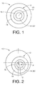
- a multifocal ocular lens in the form of a contact lens 10 constructed according to one embodiment of the present invention.
- This contact lens 10 includes, at its central portion, a vision correction area 12 providing a vision correction power for correcting the vision of the lens user.
- the vision correction area 12 has an optical center axis P which is aligned with a geometric center axis O of the lens, which is a center of a circle defined by the periphery of the lens.
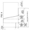
- the optical center axis P may be suitably offset from the geometric center O of the lens, depending upon the position of the pupil and the shape of the cornea of the lens user, as shown in Fig. 2 by way of example.
- the optical center axis P of the vision correction area 12 be offset from the geometric center O of the lens by a distance of not larger than 2.0mm, toward a side portion of the contact lens 10, which side portion is to be located on the side of the nose of the lens user when the contact lens is worn on the user's eye.
- the optical center axis P is easily aligned with the center of the pupil, so that the contact lens effectively achieves an enhanced vision correction performance.
- the optical center axis P of the vision correction area 12 of the contact lens 10 may also be offset from the geometric center axis O of the contact lens in the downward direction as shown in Fig. 2 or in the upward direction, depending upon the living environment or lifestyle of the lens user.
- the optical center axis P can be easily aligned with the center of the pupil.
- the contact lens is provided with a suitable rotation preventive mechanism for preventing rotational displacement of the lens in its circumferential direction during its use on the eye.
- a prism ballast mechanism is preferably employed.
- the contact lens which employs the prism ballast mechanism has a gravity center at a relatively lower portion thereof, by increasing the thickness of the lower portion, whereby the contact lens can be placed on the eye while maintaining the desired circumferential orientation. Since the prism ballast mechanism is known in the art, a detailed description thereof is dispensed with.
- the vision correction area 12 of the contact lens 10 includes a circular intermediate-distance vision correction region 14, a radially inner annular vision correction region 16, and a radially outer annular vision correction region 18, which vision correction regions 14, 16, 18 provide respective different values of optical power, which are suitably determined.
- the intermediate-distance vision correction region 14, and the inner and outer annular vision correction regions 16, 18 have their centers on a common optical center axis, i.e., on the optical center axis P of the vision correction area 12.
- the optical center axis P of the vision correction area 12 is aligned with the geometric center O.
- the circular intermediate-distance vision correction region 14 has a center located on the optical center axis P, while the radially inner and outer annular vision correction regions 16, 18 are located radially outwardly of and concentrically with the circular vision correction region 14.
- These vision correction regions 14, 16, 18 are continuously connected and formed adjacent to one another in the radial direction of the contact lens 10, to thereby provide the vision correction area 12. It is noted that the vision correction regions 14, 16, 18 have a truly circular or annular shape.
- the vision correction region 14 and the vision correction regions 16, 18 may be formed to have an elliptical shape and an elliptically annular shape.
- the radially inner and outer vision correction regions 16, 18 having respective different values of optical power function as one and the other of a near vision correction region and a distant vision correction region.
- the near vision correction region provides a constant vision correction power for correcting the user's near vision over a selected portion or preferably an entire portion of its radial width or dimension.
- the distant vision correction region provides a constant vision correction power for correcting the user's distant vision over a selected portion or preferably an entire portion of its radial width or dimension.
- the inner and outer annular vision correction regions 16, 18 are used as one and the other of the near and distant vision correction regions, respectively.
- annular correction regions 16, 18 When the annular correction regions 16, 18 are located radially outwardly of and concentrically with the central intermediate-distance vision correction region 14, the two regions 16, 18 which are formed adjacent to each other in the embodiment of Figs. 1 and 2 may be preferably spaced from each other in the radial direction by an annular second intermediate-distance vision correction region 22 interposed therebetween, as shown in Fig. 3, in view of a large difference between the optical power values of the inner and outer annular vision correction regions 16, 18.
- This annular second intermediate-distance vision correction region 22, which has a suitable radial width, preferably provides an optical power which is intermediate between the optical power values of the annular near and distant vision correction regions 16, 18, so that the contact lens is less likely to suffer from a problem of ghosting or double imaging.
- the central circular first intermediate-distance vision correction region 14 provides, over its entire area, a constant optical power between the optical power values of the annular near and distant vision correction regions 16, 18.
- the first intermediate-distance vision correction region 14 provides the optical power for correcting the user's vision for viewing an object at a distance intermediate between the two distances to which the optical power values of the annular near and distant vision correction regions 16, 18 are tuned respectively.
- the present contact lenses 10 of Figs. 1-3 permit the user to have a clear viewing of the object at the intermediate distance, based on the optical power value of the first intermediate-distance vision correction region 14.
- the inner surface (i.e., the spherical concave surface) of the contact lens 10 be formed as a base curved surface having a profile following that of the cornea of the lens user's eye.
- the vision correction regions 14, 16, 18 of the contact lens 10 are given the respective different optical power values, by adjusting the configuration of its outer surface (i.e., the spherical convex surface).
- the optical power values of the vision correction regions 14, 16, 18 can be tuned to the respective desired values, by adjusting the configurations of both of its inner and outer surfaces, or by adjusting the configuration of the inner surface only.
- the opposite inner and outer surfaces of the contact lens generally have spherical configurations (spherical portions) corresponding to the inner and outer annular vision correction regions 16, 18, so that the optical power values of these two regions 16, 18 are constant over their entire areas.
- either one of the inner and outer surfaces of the contact lens has a toric portion corresponding to the vision correction area 12.
- the contact lens has different values of optical power in different diametric directions.
- the optical power values of these regions 14, 16, 18 are suitably determined depending upon the user's visual requirements and lifestyle or living environment. Some examples of determining the optical power values of the vision correction regions 14, 16, 18 of the contact lens 10 having the second intermediate-distance vision correction region 22 will be described referring to graphs showing a distribution of the optical power of the lens in its radial direction.
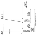
- the central circular first intermediate-distance vision correction region 14 is a constant-power section 20 whose optical power value Pa is constant over its entire radial dimension
- the annular second intermediate-distance vision correction region 22 is a varying-power section whose optical power continuously varies from an optical power value of the inner annular vision correction region 16 toward an optical power value of the outer annular vision correction region 18.
- the contact lens whose optical power distribution is indicated by the graph of Fig. 4 has the radially outer distant vision correction region 18 having a constant optical power value Pc for correcting the user's distant vision, and the radially inner near vision correction region 16 having a constant optical power value Pb for correcting the user's near vision.
- the optical power value Pa of this constant-power section 20 is preferably made closer to the optical power value Pc of the outer annular vision correction region 18, than to the optical power value Pb of the inner annular vision correction region 16, as shown in the graphs of Figs. 4 and 5. This arrangement is effective to assure significantly enhanced viewing or imaging of the object at the intermediate distance.
- the visual acuity of the near or distant object which is to be provided by the outer vision correction region 18 can be effectively maintained or compensated for, even where the optical center axis P of the vision correction area 12 is not located on the center of the pupil due to an error in the position of the optical center axis P or a displacement of the lens during its use on the eye, which results in a decrease in the effective area of the outer vision correction region 18 for correcting the user's near or distant vision.
- the optical power Pa (Dptr.) of the single constant-power section 20 formed in the central first intermediate-distance vision correction region 14 is preferably determined so as to satisfy the following formula: Pc + 0.25 ⁇ Pa ⁇ Pc + ADD/2
- the contact lens achieves a considerably high degree of visual acuity of the object at an intermediate distance, based on the vision correction performance to be exhibited by the first intermediate-distance vision correction region 14.
- the inner near vision correction region 16 is capable of receiving an amount of light sufficient for near viewing, owing to the optical characteristics of the first intermediate-distance vision correction region 14 and the outer distant vision correction region 18.
- the optical power of the annular second intermediate-distance vision correction region 22 continuously varies in the radial direction of the lens.
- This second intermediate-distance vision correction region 22 eliminates discontinuity of the optical power at the boundary between the inner and outer near and distant vision correction regions 16, 18.
- the second intermediate-distance vision correction region 22 may have a radial distribution of optical power represented by a linear equation or expression, such that the optical power of the second intermediate-distance vision correction region 22 linearly varies between the optical powers Pb, Pc of the near and distant vision correction regions 16, 18.
- the second intermediate-distance vision correction region 22 have a radial distribution of optical power value which is represented by one polynomial equation of second or higher degree or order.
- the optical power y of the second intermediate-distance vision correction region 22 at a radial distance x from the optical center axis P of the vision correction area 12 be determined as described below, by reference to some formulas wherein Pb, Pc, Wc and Wd respectively represent the optical power of the radially inner vision correction region 16, the optical power of the radially outer vision correction region 18, a radial distance from the optical center axis P to a boundary between the inner vision correction region 16 and the second intermediate-
- the distribution of the optical power (y, Pb, Pc) in the radial direction may be represented by a line in a coordinate system wherein the optical power is taken along the ordinate (y axis) while the radial distance (x) or position (Wb, Wd) is taken along the abscissa (x axis).
- the optical power values Pb, Pc of the vision correction regions 16, 18 are represented by respective two straight lines parallel to the abscissa or x axis.
- the line representing the optical power y of the second intermediate-distance vision correction region 22 is tangent at its opposite ends to the above-indicated two straight lines at respective two coordinate points (Wc, Pb) and (Wd, Pc), as indicated in Figs.
- E2 and F2 E2(x 3 /3-x 2 (Wc+Wd)/2+x ⁇ Wc ⁇ Wd)+F2
- E2 E2(Wc 3 /3-Wc 2 (Wc+Wd)/2+Wc ⁇ Wc ⁇ Wd)+F2
- Pc E2(Wd 3 /3-Wd 2 (Wc+Wd)/2+Wd ⁇ Wc ⁇ Wd)+F2
- E2 (Pb-Pc)/((Wc 3 -Wd 3 )/3-(Wc 2 -Wd 2 )(Wc+Wd)/2+(Wc-Wd)Wc ⁇ Wd)
- F2 Pb-E2(Wc 3 /3-Wc 2 (Wc+Wd)/2+Wc ⁇ Wc ⁇ Wd)
- this vision correction region 22 preferably has a radial width of 0.1-2.0mm between the outer and inner peripheries of the inner and outer annular vision correction regions 16, 18.
- the first intermediate-distance vision correction region 14 has the optical power value Pa which is constant over its entire area, so that the entire area of the central circular region 14 functions as the constant-power section 20.
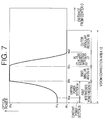
- the first intermediate-distance vision correction region 14 may include a transition section or varying-power section 24 formed at its radially outer portion with a suitable radial width, as shown in Fig. 6.
- the constant-power section 20 is formed at a central portion of the first intermediate-distance vision correction region 14 and located radially inwardly of the varying-power section 24.
- This varying-power section 24 provides an optical power which continuously varies in the radial direction of the lens 10 from the optical power value of the constant-power section 20 to the optical power value of the radially inner annular vision correction region 16.
- the contact lens 10 which includes the thus formed varying-power section 24 assures a high degree of visual acuity of the objects in a relatively wide range of the intermediate distance between the near and far distances to which the radially inner and outer vision correction regions 16, 18 are tuned. Further, this arrangement is effective to reduce the ghosting or double imaging problem.
- the varying-power section 24 of the first intermediate-distance vision correction region 14 is interposed between the constant-power section 20 and the radially inner vision correction region 16, with a radial width of 0.1-2.0mm. If the radial width of the varying-power section 24 is too small, this section 24 does not exhibit the intended effect described above. On the other hand, if the radial width of the varying-power section 24 is too large, the sizes of the constant-power section 20 and the radially inner and outer vision correction regions 16, 18 tend to be insufficient.
- the varying-power section 24 of the first intermediate-distance vision correction region 14 may have a radial distribution of optical power represented by a linear equation, so that the varying-power section 24 has the optical power which linearly varies between the optical power value Pa of the constant-power section 20 and the optical power value Pb of the inner annular vision correction region 16.
- the varying-power section 24 it is preferable that the varying-power section 24 have a radial distribution of optical power represented by one polynomial equation of second or higher degree or order, to thereby assure a high degree of freedom in tuning the optical power values of the vision correction regions 14, 16, 18 to permit clear viewing or imaging of the near, far and intermediate objects.
- the first intermediate-distance vision correction area 14 and the radially inner vision correction region 16 have a common optical center axis at the optical center axis P of the vision correction area 12, and the first intermediate-distance vision correction region 14 consists of the constant-power section 20 whose center is located on its optical center, and the varying-power section 24 formed radially outwardly of the constant-power section 20.
- the optical power y of the varying-power section 24 of the first intermediate-distance vision correction region 14 at the radial distance x from the optical center axis P of the vision correction area 12 be determined as described below, by reference to some formulas wherein Pa, Pb, Wa and Wb respectively represent the optical power of the constant-power section 20, the optical power of the radially inner vision correction region 16, a radial distance from the optical center axis P to a boundary between the constant-power section 20 and the varying-power section 24, and a radial distance from the optical center axis P to a boundary between the first intermediate-distance vision correction region 14 and the radially inner vision correction region 16.
- the above-indicated radial distances Wa and Wb are determined to satisfy the formula 0 ⁇ Wa ⁇ Wb.
- the distribution of the optical power (y, Pa, Pb) in the radial direction may be represented by a line in the coordinate system wherein the optical power is taken along the ordinate (y axis) while the radial distance (x) or position (Wa, Wb) is taken along the abscissa (x axis).
- the optical power values Pa, Pb of the constant-power section 20 and the inner annular vision correction region 16 are represented by respective two straight lines parallel to the abscissa or x axis.
- the line representing the optical power y of the varying-power section 24 is tangent at its opposite ends to the above-indicated two straight lines at respective two coordinate points (Wa, Pa) and (Wb, Pb).
- y E1(x 3 /3-x 2 (Wa+Wb)/2+x ⁇ Wa ⁇ Wb)+F1
- the optical power y of the varying-power section 24 can be determined so as to be represented by an expression of the fourth order, rather than the above-described expression of the third order.
- the contact lenses whose optical power distributions are indicated by the respective graphs of Figs.
- the rate of change of the optical power y of the varying-power section 24 changes abruptly to zero at a junction between the section 24 and either one of the constant-power section 20 and the inner vision correction region 16, but smoothly to zero at a junction between the section 24 and the other of the constant-power section 20 and the inner vision correction region 16.
- These different rates of change of the optical power y in the radially inner and outer end portions of the varying-power section 24 are represented by a straight line and a curved line.
- the different rates of change of the optical power y in the radially inner and outer end portions of the varying-power section 20 assure a high degree of freedom in designing the contact lens regarding light-receiving capability and/or visual acuity in the constant-power section 20 or the inner vision correction region 16.
- this section 24 interposed between the constant-power section 20 and the inner vision correction region 16 desirably has a radial width or radius of 0.1-3.0mm, preferably 0.5-2.0mm. If the radial width of the varying-power section 24 is too small, the section 24 does not exhibit the intended effect. On the other hand, if the radial width of the varying-power section 24 is too large, the sizes of the constant-power section 20 and the radially inner and outer vision correction regions 16, 18 tend to be insufficient.
- the central first intermediate-distance vision correction region 14 includes the constant-power section 20 which has a radial width or radius Wa and the constant optical power value Pa which is between the optical power values Pb and Pc of the inner and outer annular near and distant vision correction regions 16, 18.
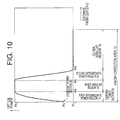
- the first intermediate-distance vision correction region 14 need not include the constant-power section 20, and may consist of only the varying-power section 24 whose optical power continuously varies from a first extreme value Pa at the optical center axis P to a second extreme value Pb of the inner vision correction region 16, as shown in the graphs of Figs. 10 and 11.
- the contact lens assures clear viewing of the objects in a relatively wide range of the intermediate distance between the near and far distances.
- the contact lens of Fig. 11 wherein the first intermediate-distance vision correction region 14 consists of only the varying-power section 24 may be modified such that the first extreme optical power value Pa at the optical center axis P of the vision correction area 12 is equal to the constant optical power value Pc of the outer annular vision correction region 18.
- the contact lens assures clear viewing of the objects over the entire range of the intermediate distance between the near and far distances.
- the first extreme value Pa in Fig. 7 is the minimal value
- the second extreme value Pb in Fig. 8 is the maximal value
- the second extreme value Pb in Fig. 9 is the minimal value.
- the first extreme optical power value Pa is the smallest value at the optical center axis P
- the second extreme optical power value Pb is the largest value at which the continuous increase of the optical value of the varying-power section 24 is terminated.
- the first extreme optical power value Pa is the largest value at the optical center axis P
- the second extreme optical power value Pb is the smallest value at which the continuous decrease of the optical value of the varying-power section 24 is terminated.
- the optical power distribution in a certain portion of the intermediate-distance vision correction region 14 may be represented by a functional equation including the radial distance as a variable.
- the maximal and minimal points are points at which the differential coefficient is zero.
- the extreme value is a point to which the optical value increases or decreases.
- the first intermediate-distance vision correction region 14 consists of the radially inner constant-power section 20 and the radially outer varying-power section 24 as shown in Figs. 6-9, or alternatively consists of only the varying-power section 24 as shown in Figs. 10 and 11.
- the radius of the constant-power section 20 is preferably selected within a range of 0-3.0mm.
- the constant-power section 20 whose radius is larger than 3.0mm tends to reduce the sizes of the near and distant vision correction regions 16, 18.
- the principle of the present invention is applicable to various types of ocular lenses irrespective of the applications and materials.
- the present invention is applicable to hard contact lenses and soft contact lenses.
- the hard contact lenses include a non-rigid gas permeable type formed of PMMA, for example, and a rigid gas permeable type (RGP).
- the soft contact lenses include a hydrophilic or hydrated type and a hydrophobic type.
- the present invention is applicable to intraocular lenses.
- the ocular lens according to the present invention may be produced by any known methods.
- the ocular lens is produced by first cutting a lens blank to provide a precursor of an intended lens, and then shaping or forming the inner and outer surfaces of the precursor by a suitable cutting or machining operation.
- the ocular lens may be formed by a molding operation using a pair of molds which respectively give intended inner and outer surfaces of the lens.
- one of the opposite surfaces of the ocular lens is formed by molding while the other surface is formed by cutting.
- a molded lens blank may be subjected to a cutting operation to form the desired inner and outer surface configurations.
- the ocular lens is formed by cutting, the surfaces of the obtained ocular lens have a high degree of accuracy of configuration.
- the ocular lens is formed by molding, the ocular lens can be produced with high efficiency. By combining the cutting operation and the molding operation, the ocular lens can be produced with high efficiency while assuring high accuracy of the surface configuration.
- the multifocal ocular lens of the present invention is also used as a translating vision type ocular lens, by suitably determining the offset distance of the optical center axis of the vision correction area from the geometric center axis of the lens, and the sizes of the respective vision correction regions.
- a translating vision type ocular lens includes a vision correction area consisting of a central circular first intermediate-distance vision correction region formed at its center, a distant vision correction region, and a near vision correction region.
- Each of the distant and near vision correction regions has a semi-annular shape extending over a circumferential distance corresponding to a half of the circumference of the first intermediate-distance vision correction region, so that the semi-annular distant and near vision correction regions cooperate to surround the central first intermediate-distance vision correction region.
- This ocular lens employs a suitable rotation preventive mechanism such as a prism ballast mechanism.
- the thus formed ocular lens is used as the translating vision type ocular lens, wherein the near vision correction region is located below a horizontal line passing the first intermediate-distance vision correction region, and the distant vision correction region is located above the horizontal line.
- the visual axis of the lens wearer who wears the thus formed translating vision type ocular lens is directed downwards while reading a book, for instance, a relatively wide area of the pupil of the wearer's eye is covered by the near vision correction region and the first intermediate-distance vision correction region, so that the wearer can obtain clear images of the relatively near object (book) and objects at an intermediate distance between the near and far distances to which the optical power values of the near and distant vision correction regions are respectively tuned.
- the visual axis of the lens wearer is directed frontwards while driving a car, for instance, a relatively wide area of the pupil is covered by the distant vision correction region and the first intermediate-distance vision correction region, so that the wearer can obtain clear images of the far objects and the intermediate objects.
- a pair of inner and outer annular vision correction regions 16, 18 are formed radially outwardly of the central circular first intermediate-distance vision correction region 14.
- a plurality of pairs of inner and outer annular vision correction regions each having a suitable radial width may be formed, such that the inner and outer vision correction regions 16, 18 are alternately arranged in the radial direction of the lens.
- the contact lens includes a single constant-power section 20 formed in the central (first) intermediate-distance vision correction region 14.
- the central intermediate-distance vision correction region 14 may include a plurality of constant-power sections 20, as shown in the graph of Fig. 12 by way of example.
- the central first intermediate-distance vision correction region 14 consists of a radially inner central circular first constant-power section 20a and a radially outer annular second constant-power section 20b, which have respective different optical power values Pa1 and Pa2.
- the optical power value Pa1 of the radially inner first constant-power section 20a be made closer to the optical power Pb of the radially inner vision correction region 16, than the optical power value Pa2 of the radially outer second constant-power section 20b. More preferably, the optical power Pa1 of the first constant-power section 20a is made closer to the optical power Pb of the inner vision correction region 16, than to the optical power Pc of the outer vision correction region 18, while the optical power Pa2 of the second constant-power section 20b is made closer to the optical power Pc than to the optical power Pb.
- the plurality of constant-power sections provided in the central intermediate-distance vision correction region 14 permit enhanced visual acuity of objects at respective intermediate distances to which the optical power values Pa of the respective constant-power sections are tuned.
- the optical power value Pa of each constant-power section is selected to be intermediate between the optical power values Pb and Pc of the near and distant vision correction regions 16, 18.
- the optical power of the second intermediate-distance vision correction region 22 is determined to be held within a range between those of the near and distant vision correction regions 16, 18 so that the contact lens advantageously assures a high degree of visual acuity of the objects at the intermediate distance while avoiding the ghosting or double imaging problem.
- the optical power of the second intermediate-distance vision correction region 22 continuously varies from the optical power value Pb of the inner annular vision correction region 16 to the optical power value Pc of the outer annular vision correction region 18.
- the annular second intermediate-distance vision correction region 22 may include at least one constant-power section each having a desired constant intermediate optical power value over a suitable radial distance.
- the multifocal ocular lens constructed according to the present invention includes a central intermediate-distance vision correction region whose optical power is held within a range between the respective different optical power values of the near and distant vision correction regions, which are formed radially outwardly of the central intermediate-distance vision correction region.
- the ocular lens having the central intermediate-distance vision correction region assures improved visual acuity of objects at an intermediate distance between the near and far distances, owing to the optical characteristics of the central intermediate-distance vision correction region, while effectively preventing the ghosting or double imaging problem. Further, the present ocular lens prevents or minimizes deterioration of the visual acuity which would be caused by displacement of the lens during its use on the user's eye.
Landscapes
- Health & Medical Sciences (AREA)
- Ophthalmology & Optometry (AREA)
- Physics & Mathematics (AREA)
- General Health & Medical Sciences (AREA)
- General Physics & Mathematics (AREA)
- Optics & Photonics (AREA)
- Eyeglasses (AREA)
- Prostheses (AREA)
Applications Claiming Priority (2)
| Application Number | Priority Date | Filing Date | Title |
|---|---|---|---|
| JP10294999A JP2000122006A (ja) | 1998-10-16 | 1998-10-16 | 多焦点型眼用レンズ |
| JP29499998 | 1998-10-16 |
Publications (1)
| Publication Number | Publication Date |
|---|---|
| EP0994376A1 true EP0994376A1 (fr) | 2000-04-19 |
Family
ID=17815037
Family Applications (1)
| Application Number | Title | Priority Date | Filing Date |
|---|---|---|---|
| EP99308075A Withdrawn EP0994376A1 (fr) | 1998-10-16 | 1999-10-13 | Lentille oculaire multifocale avec une zone de correction pour la distance intermediaire |
Country Status (3)
| Country | Link |
|---|---|
| US (1) | US6357876B1 (fr) |
| EP (1) | EP0994376A1 (fr) |
| JP (1) | JP2000122006A (fr) |
Cited By (3)
| Publication number | Priority date | Publication date | Assignee | Title |
|---|---|---|---|---|
| WO2008055031A3 (fr) * | 2006-10-30 | 2008-07-31 | Johnson & Johnson Vision Care | Procédé de conception de lentilles de contact multifocales |
| WO2011038520A1 (fr) * | 2009-09-30 | 2011-04-07 | Aha Informatik Ag | Lentille de contact bifocale ou multifocale |
| EP4468066A1 (fr) * | 2023-05-26 | 2024-11-27 | UNICON Optical Co., LTD. | Lentilles de contact |
Families Citing this family (14)
| Publication number | Priority date | Publication date | Assignee | Title |
|---|---|---|---|---|
| US6474814B1 (en) * | 2000-09-08 | 2002-11-05 | Florida Optical Engineering, Inc | Multifocal ophthalmic lens with induced aperture |
| US6666887B1 (en) * | 2000-10-20 | 2003-12-23 | Thinoptx, Inc. | Deformable intraocular multi-focus lens |
| AUPR276601A0 (en) * | 2001-01-31 | 2001-02-22 | Newman, Steve | A contact lens for refractive correction and capable of engagement with an eye either inside out or right way out |
| US7101042B2 (en) | 2003-08-12 | 2006-09-05 | S.I.B. Investments Llc | Multifocal contact lens |
| US6929366B2 (en) * | 2003-08-12 | 2005-08-16 | S.I.B. Invesrements Llc | Multifocal contact lens |
| US20050041203A1 (en) * | 2003-08-20 | 2005-02-24 | Lindacher Joseph Michael | Ophthalmic lens with optimal power profile |
| US7044597B2 (en) | 2003-12-16 | 2006-05-16 | Bausch & Lomb Incorporated | Multifocal contact lens and method of manufacture thereof |
| US20080297721A1 (en) * | 2007-05-29 | 2008-12-04 | Amitava Gupta | Lens designs for treating asthenopia caused by visual defects |
| US7753521B2 (en) * | 2008-03-31 | 2010-07-13 | Johnson & Johnson Vision Care, Inc. | Lenses for the correction of presbyopia and methods of designing the lenses |
| JP5410739B2 (ja) * | 2008-12-01 | 2014-02-05 | 株式会社ニデック | 多焦点眼内レンズの製造方法 |
| WO2011151839A2 (fr) * | 2010-05-31 | 2011-12-08 | Ram Srikanth Mirlay | Ensemble optique concentré sur une fovéa et centré sur une pupille pour une lentille intraoculaire |
| EP3153914B1 (fr) * | 2014-06-04 | 2023-12-20 | Hoya Lens Thailand Ltd. | Lentille de contact a puissance progressive |
| US11660180B2 (en) * | 2018-04-25 | 2023-05-30 | The Regents Of The University Of California | Intraoperative assessment of implant positioning |
| CN111679449B (zh) * | 2020-06-29 | 2025-05-02 | 欧普康视科技股份有限公司 | 多焦点硬性角膜接触镜及其设计方法 |
Citations (5)
| Publication number | Priority date | Publication date | Assignee | Title |
|---|---|---|---|---|
| US4580882A (en) * | 1983-04-21 | 1986-04-08 | Benjamin Nuchman | Continuously variable contact lens |
| US5002382A (en) * | 1989-12-07 | 1991-03-26 | Leonard Seidner | Multifocal corneal contact lenses |
| EP0742464A2 (fr) * | 1995-05-04 | 1996-11-13 | JOHNSON & JOHNSON VISION PRODUCTS, INC. | Lentille ophtalmique multifocale |
| EP0766951A1 (fr) * | 1991-06-18 | 1997-04-09 | Allergan, Inc | Lentille ophtamalmic multifocal |
| US5691797A (en) * | 1993-03-31 | 1997-11-25 | Permeable Technologies, Inc. | Multifocal contact lens |
Family Cites Families (4)
| Publication number | Priority date | Publication date | Assignee | Title |
|---|---|---|---|---|
| JPS6395415A (ja) | 1986-10-09 | 1988-04-26 | Nobuko Takimoto | 老眼用コンタクトレンズ |
| JPH01319729A (ja) | 1988-06-21 | 1989-12-26 | Shiro Sato | 三重焦点コンタクトレンズ |
| JPH02217818A (ja) | 1989-02-20 | 1990-08-30 | Nippon Contact Lens Kk | 老視用コンタクトレンズ |
| JP3171629B2 (ja) | 1991-12-28 | 2001-05-28 | 株式会社メニコン | マルチフォーカル眼用レンズおよびその製作方法 |
-
1998
- 1998-10-16 JP JP10294999A patent/JP2000122006A/ja active Pending
-
1999
- 1999-10-12 US US09/416,759 patent/US6357876B1/en not_active Expired - Fee Related
- 1999-10-13 EP EP99308075A patent/EP0994376A1/fr not_active Withdrawn
Patent Citations (5)
| Publication number | Priority date | Publication date | Assignee | Title |
|---|---|---|---|---|
| US4580882A (en) * | 1983-04-21 | 1986-04-08 | Benjamin Nuchman | Continuously variable contact lens |
| US5002382A (en) * | 1989-12-07 | 1991-03-26 | Leonard Seidner | Multifocal corneal contact lenses |
| EP0766951A1 (fr) * | 1991-06-18 | 1997-04-09 | Allergan, Inc | Lentille ophtamalmic multifocal |
| US5691797A (en) * | 1993-03-31 | 1997-11-25 | Permeable Technologies, Inc. | Multifocal contact lens |
| EP0742464A2 (fr) * | 1995-05-04 | 1996-11-13 | JOHNSON & JOHNSON VISION PRODUCTS, INC. | Lentille ophtalmique multifocale |
Cited By (6)
| Publication number | Priority date | Publication date | Assignee | Title |
|---|---|---|---|---|
| WO2008055031A3 (fr) * | 2006-10-30 | 2008-07-31 | Johnson & Johnson Vision Care | Procédé de conception de lentilles de contact multifocales |
| US7481533B2 (en) | 2006-10-30 | 2009-01-27 | Johnson & Johnson Vision Care, Inc | Method for designing multifocal contact lenses |
| RU2429511C2 (ru) * | 2006-10-30 | 2011-09-20 | Джонсон Энд Джонсон Вижн Кэа, Инк. | Способ конструирования мультифокальных контактных линз |
| CN101563641B (zh) * | 2006-10-30 | 2013-07-24 | 庄臣及庄臣视力保护公司 | 设计多焦点隐形眼镜的方法 |
| WO2011038520A1 (fr) * | 2009-09-30 | 2011-04-07 | Aha Informatik Ag | Lentille de contact bifocale ou multifocale |
| EP4468066A1 (fr) * | 2023-05-26 | 2024-11-27 | UNICON Optical Co., LTD. | Lentilles de contact |
Also Published As
| Publication number | Publication date |
|---|---|
| US6357876B1 (en) | 2002-03-19 |
| JP2000122006A (ja) | 2000-04-28 |
Similar Documents
| Publication | Publication Date | Title |
|---|---|---|
| US6286956B1 (en) | Multifocal ocular lens including intermediate vision correction region between near and distant vision correction regions | |
| US6260966B1 (en) | Multifocal ocular lens | |
| EP0942312B1 (fr) | Lentille oculaire multifocale avec une région intermédiaire dont la puissance optique varie continuellement | |
| US6357876B1 (en) | Multifocal ocular lens having intermediate-distance vision correction region formed in central part of vision correction area | |
| US6199982B1 (en) | Presbyopia correction contact lens | |
| JP4674346B2 (ja) | プログレッシブアディション・レンズ | |
| JP5323026B2 (ja) | 変化する屈折力プロファイルを有する進行付加型レンズ | |
| JP3882764B2 (ja) | 累進屈折力レンズ | |
| US6899425B2 (en) | Multifocal ophthalmic lenses | |
| JP4954358B2 (ja) | コンタクトレンズ及びその製造方法 | |
| US6733124B2 (en) | Contact lens | |
| JP4476995B2 (ja) | オプチカルゾーンブレンドデザインを有する眼科用レンズ | |
| US20050134793A1 (en) | Multifocal contact lenses having a pinhole | |
| US6726323B2 (en) | Contact lens and method of designing the same | |
| JPWO2008062503A1 (ja) | コンタクトレンズおよびコンタクトレンズの製造方法 | |
| JP4618656B2 (ja) | 累進多焦点レンズシリーズ | |
| JP2000122007A (ja) | 多焦点型眼用レンズ | |
| JP2000199876A (ja) | 多焦点型眼用レンズ | |
| JPH11258554A (ja) | 多焦点型眼用レンズ | |
| WO2003069393A1 (fr) | Lentilles de contact comportant une surface spherique decentree | |
| JP2004294456A (ja) | 多焦点型眼用レンズ | |
| JP4450480B2 (ja) | 累進多焦点レンズシリーズ | |
| JPH085967A (ja) | 非球面眼鏡レンズ | |
| CA1244687A (fr) | Lentilles de contact | |
| JP2000122008A (ja) | 多焦点型眼用レンズ |
Legal Events
| Date | Code | Title | Description |
|---|---|---|---|
| PUAI | Public reference made under article 153(3) epc to a published international application that has entered the european phase |
Free format text: ORIGINAL CODE: 0009012 |
|
| 17P | Request for examination filed |
Effective date: 19991102 |
|
| AK | Designated contracting states |
Kind code of ref document: A1 Designated state(s): DE FR GB |
|
| AX | Request for extension of the european patent |
Free format text: AL;LT;LV;MK;RO;SI |
|
| AKX | Designation fees paid |
Free format text: DE FR GB |
|
| 17Q | First examination report despatched |
Effective date: 20050602 |
|
| STAA | Information on the status of an ep patent application or granted ep patent |
Free format text: STATUS: THE APPLICATION IS DEEMED TO BE WITHDRAWN |
|
| 18D | Application deemed to be withdrawn |
Effective date: 20051013 |