EP0994476A1 - Magnetplattengerät mit niedriger Auftrittswahrscheinlichkeit von Lesefehlern aufgrund von Kratzern oder dergleichen auf der Magnetplattenoberfläche - Google Patents
Magnetplattengerät mit niedriger Auftrittswahrscheinlichkeit von Lesefehlern aufgrund von Kratzern oder dergleichen auf der Magnetplattenoberfläche Download PDFInfo
- Publication number
- EP0994476A1 EP0994476A1 EP99308104A EP99308104A EP0994476A1 EP 0994476 A1 EP0994476 A1 EP 0994476A1 EP 99308104 A EP99308104 A EP 99308104A EP 99308104 A EP99308104 A EP 99308104A EP 0994476 A1 EP0994476 A1 EP 0994476A1
- Authority
- EP
- European Patent Office
- Prior art keywords
- time
- read
- magnetic disk
- stm
- gate
- Prior art date
- Legal status (The legal status is an assumption and is not a legal conclusion. Google has not performed a legal analysis and makes no representation as to the accuracy of the status listed.)
- Withdrawn
Links
Images


Classifications
-
- G—PHYSICS
- G11—INFORMATION STORAGE
- G11B—INFORMATION STORAGE BASED ON RELATIVE MOVEMENT BETWEEN RECORD CARRIER AND TRANSDUCER
- G11B5/00—Recording by magnetisation or demagnetisation of a record carrier; Reproducing by magnetic means; Record carriers therefor
- G11B5/48—Disposition or mounting of heads or head supports relative to record carriers ; arrangements of heads, e.g. for scanning the record carrier to increase the relative speed
- G11B5/58—Disposition or mounting of heads or head supports relative to record carriers ; arrangements of heads, e.g. for scanning the record carrier to increase the relative speed with provision for moving the head for the purpose of maintaining alignment of the head relative to the record carrier during transducing operation, e.g. to compensate for surface irregularities of the latter or for track following
- G11B5/596—Disposition or mounting of heads or head supports relative to record carriers ; arrangements of heads, e.g. for scanning the record carrier to increase the relative speed with provision for moving the head for the purpose of maintaining alignment of the head relative to the record carrier during transducing operation, e.g. to compensate for surface irregularities of the latter or for track following for track following on disks
-
- G—PHYSICS
- G11—INFORMATION STORAGE
- G11B—INFORMATION STORAGE BASED ON RELATIVE MOVEMENT BETWEEN RECORD CARRIER AND TRANSDUCER
- G11B20/00—Signal processing not specific to the method of recording or reproducing; Circuits therefor
- G11B20/10—Digital recording or reproducing
- G11B20/12—Formatting, e.g. arrangement of data block or words on the record carriers
- G11B20/1217—Formatting, e.g. arrangement of data block or words on the record carriers on discs
-
- G—PHYSICS
- G11—INFORMATION STORAGE
- G11B—INFORMATION STORAGE BASED ON RELATIVE MOVEMENT BETWEEN RECORD CARRIER AND TRANSDUCER
- G11B20/00—Signal processing not specific to the method of recording or reproducing; Circuits therefor
- G11B20/10—Digital recording or reproducing
- G11B20/18—Error detection or correction; Testing, e.g. of drop-outs
- G11B20/1816—Testing
-
- G—PHYSICS
- G11—INFORMATION STORAGE
- G11B—INFORMATION STORAGE BASED ON RELATIVE MOVEMENT BETWEEN RECORD CARRIER AND TRANSDUCER
- G11B27/00—Editing; Indexing; Addressing; Timing or synchronising; Monitoring; Measuring tape travel
- G11B27/10—Indexing; Addressing; Timing or synchronising; Measuring tape travel
- G11B27/19—Indexing; Addressing; Timing or synchronising; Measuring tape travel by using information detectable on the record carrier
- G11B27/28—Indexing; Addressing; Timing or synchronising; Measuring tape travel by using information detectable on the record carrier by using information signals recorded by the same method as the main recording
- G11B27/30—Indexing; Addressing; Timing or synchronising; Measuring tape travel by using information detectable on the record carrier by using information signals recorded by the same method as the main recording on the same track as the main recording
- G11B27/3027—Indexing; Addressing; Timing or synchronising; Measuring tape travel by using information detectable on the record carrier by using information signals recorded by the same method as the main recording on the same track as the main recording used signal is digitally coded
-
- G—PHYSICS
- G11—INFORMATION STORAGE
- G11B—INFORMATION STORAGE BASED ON RELATIVE MOVEMENT BETWEEN RECORD CARRIER AND TRANSDUCER
- G11B20/00—Signal processing not specific to the method of recording or reproducing; Circuits therefor
- G11B20/10—Digital recording or reproducing
- G11B20/12—Formatting, e.g. arrangement of data block or words on the record carriers
- G11B2020/1264—Formatting, e.g. arrangement of data block or words on the record carriers wherein the formatting concerns a specific kind of data
- G11B2020/1265—Control data, system data or management information, i.e. data used to access or process user data
- G11B2020/1281—Servo information
-
- G—PHYSICS
- G11—INFORMATION STORAGE
- G11B—INFORMATION STORAGE BASED ON RELATIVE MOVEMENT BETWEEN RECORD CARRIER AND TRANSDUCER
- G11B20/00—Signal processing not specific to the method of recording or reproducing; Circuits therefor
- G11B20/10—Digital recording or reproducing
- G11B20/14—Digital recording or reproducing using self-clocking codes
- G11B20/1403—Digital recording or reproducing using self-clocking codes characterised by the use of two levels
- G11B2020/1476—Synchronisation patterns; Coping with defects thereof
-
- G—PHYSICS
- G11—INFORMATION STORAGE
- G11B—INFORMATION STORAGE BASED ON RELATIVE MOVEMENT BETWEEN RECORD CARRIER AND TRANSDUCER
- G11B20/00—Signal processing not specific to the method of recording or reproducing; Circuits therefor
- G11B20/10—Digital recording or reproducing
- G11B20/18—Error detection or correction; Testing, e.g. of drop-outs
- G11B20/1816—Testing
- G11B2020/1826—Testing wherein a defect list or error map is generated
Definitions
- the present invention relates to a magnetic disk apparatus which is capable of reducing the probability of the occurrence of read errors caused by scratches or the like on a surface of a magnetic disk.
- a sector in a recording track area thereof is provided with a servo field.
- a signal in the servo field is used for servo control when making a magnetic head seek a target track and for servo control during on-tracking.
- a data field is provided, following the servo field in one sector.
- SYNC a servo address mark (SAM), and servo information, namely, A burst and B burst, are recorded in the servo field. Synchronization is performed using the SYNC, positional information regarding the sector is read using the SAM, and a positional correction of the magnetic head is made using the A burst and the B burst.
- the data field is further provided with a SYNC area and a data area (DATA). Following synchronization accomplished by the SYNC, a data body is read from the data area.
- a read gate of a reading circuit is opened in a predetermined time on the basis of detection of a reference signal (STM) at the beginning of the SAM or in the SAM.
- STM reference signal
- the read gate is opened when a head is positioned in the SYNC area of the data field. As a result, while the read gate is open, a signal of the data body is read from the data area, following the SYNC.
- This type of a magnetic disk for high-density recording is subjected to writing and reading data for inspection during a quality inspection following a manufacturing process.
- a sector from which data cannot be properly read is determined to be a defective sector, and the number of the sector is registered as the number of a defective sector in a maintenance area of the magnetic disk.
- the maintenance area is first read, the number of the defective sector is recognized, and control is carried out so that the defective sector will not be used for recording.
- a magnetic disk apparatus having a head for reading recorded information from a disk provided with a servo field and a SYNC area and a data area following the servo field, a gate for applying a signal read by the head to a signal processing unit, and a control unit for controlling the gate; wherein the control unit carries out control such that the gate is opened after a set period of time (T1) based on a time at which a reference signal (STM) in the servo field has been detected from the signal read by the head, or the gate is opened after the elapse of a time corresponding to the set period of time (T1) from a moment at which the reference signal (STM) is supposed to be detected if the reference signal (STM) cannot be detected after a predetermined period of time (T) following the detection of a preceding reference signal (STM).
- T1 set period of time
- STM reference signal
- the present invention can be applied to a case wherein a read error of the STM in a servo field takes place due to a scratch or the like on a disk surface when an attempt is made to read, using a regular disk apparatus, data from an area which has incurred no ECC error during the quality inspection of the disk and presents a low ECC error rate, and which accordingly has not been registered as a defective sector in the maintenance area of the disk.
- control unit may continue measurement of time after the predetermined period of time (T) has passed, add the set period of time (T1) after the predetermined period of time has passed, and open the gate when a time obtained by (T+T1) has passed.
- a magnetic disk is provided with a maintenance area in which a defective sector is registered during a disk inspection, and if the STM is not detected within the predetermined period of time (T), then a sector from which the STM has not been detected is registered as a defective sector in the maintenance area during the disk inspection.
- the quality inspection before shipment a sector in which the reference signal read error has occurred is recorded as a defective sector in a maintenance field.
- the magnetic disk apparatus of preferred embodiments employs a different standard for determining a defect when registering a defective sector during a disk inspection from a standard used for regular reproduction.
- Embodiments of the present invention provide a magnetic disk apparatus capable of reading normal data following the occurrence of a read error of a reference signal (STM) in, for example, a servo field, the read error being attributable to a scratch or the like on a disk surface.
- STM reference signal
- Embodiments of the present invention also provide a magnetic disk apparatus that has a strict standard set for a read error of the STM in a quality inspection prior to the shipment of disks so as to make it possible to recognize a sector that incurs such a read error as a defective sector.
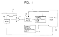
- Fig. 1 is a block diagram showing an outline of a circuit configuration of a magnetic disk apparatus.
- Fig. 2 is a schematic representation that illustrates normal reproduction processing.
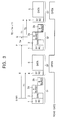
- Fig. 3 is a schematic representation that illustrates processing for correcting a read gate timing during reproduction.
- Fig. 4 is a flow chart that illustrates processing control for opening a gate.
- FIG. 1 is a block diagram showing an outline of a circuit configuration of a magnetic disk apparatus
- Fig. 2 is a schematic representation that illustrates normal reproduction processing for performing reproduction from a disk after shipment
- Fig. 3 is a schematic representation that illustrates processing for correcting a read gate timing during reproduction from the disk after shipment if a read error has occurred
- Fig. 4 is a flow chart that illustrates control conducted by a control unit of the magnetic disk apparatus.
- a magnetic disk apparatus shown in Fig. 1 is constituted primarily by a control unit 10, a signal processing unit 11, a read gate 12, a servo signal processing unit 13, an amplifier 14, a VCM 15, and a magnetic head 16 to reproduce information recorded in a disk D.
- the VCM means a voice coil motor, which is a linear motor driving unit for driving the magnetic head 16 in the radial direction of the disk D.
- Fig. 2 shows a servo field and a data field provided for each sector of the disk D.
- a data sector of the disk D has a formatted servo field SF and a formatted data field DF.
- SYNC 1 a servo address mark (SAM) 2
- a burst 3a and B burst 3b as servo information are recorded in the servo field SF.
- the data field DF has a formatted SYNC area 4 and a formatted data area 5 following the SYNC area 4, DATA having been recorded in the data area 5.
- a signal recorded on the disk D is read by the magnetic head 16, and the signal is amplified by the amplifier 14.
- Read outputs of the SYNC 1, the SAM 2, and the A burst 3a and the B burst 3b in the servo field SF are applied to the servo signal processing unit 13.
- the servo signal processing unit 13 sets a read timing on the basis of the output of the SYNC 1, reads the SAM 2 to recognize an address, and detects the output intensity levels of the A burst signal 3a and the B burst signal 3b and supplies them to the control unit 10.
- the control unit 10 calculates a difference between the output intensity level of the A burst signal 3a and the output intensity level of the B burst signal 3b. Based on a result of the calculation, the VCM 15 is servo-driven to make a tracking correction so as to make the head 16 follow a track center of the disk D.
- control unit 10 carries out processing for opening the read gate 12 at a predetermined timing. While the read gate 12 is open, signals recorded in the SYNC area 4 and the DATA area 5 of the data field DF are supplied to the signal processing unit 11 to perform processing for decoding the DATA.
- each step of the control operation implemented by the control unit 10 will be denoted as ST.
- the disk D loaded in the disk apparatus has been subjected to recording and reproduction of inspection signals during a quality inspection prior to shipment.
- Data check has been conducted on the basis of a reproduction output, and a sector with a high ECC error rate has been recorded as a defective sector in the maintenance area of the disk.
- the maintenance area is read by the head 16 shown in Fig. 1, the defective sector which has been recorded in the maintenance area is recognized, and the number of the defective sector is stored in a RAM in the control unit 10.
- the reference signal STM is detected from a reproduction signal of the servo field SF supplied from the servo signal processing unit 13 to the control unit 10.
- the STM is a rise signal or the like of the servo address mark (SAM).
- SAM servo address mark
- an output from the amplifier 14 is supplied to the signal processing unit 11.
- the timing for opening the read gate 12 after the set period of time (T1) is set so that the read gate 12 is opened during or immediately before the reproduction from the SYNC area 4 of the data field DF.
- an output of the SYNC area 4 is first supplied to the signal processing unit 11, then a DATA body of the following DATA area 5 is read by the signal processing unit 11 on the basis of a timing set by the SYNC output and subjected to a decoding process.
- the read gate 12 is opened in ST9, and an output read from the data field DF is supplied to the signal processing unit 11.
- the time Tw may be fixed beforehand, and if the STM has not been able to be read, then the time T2 may be measured after the time Tw has passed, and the read gate 12 may be opened. Further alternatively, if the STM has not been able to be read, time measurement may be continued after the set period of time (T) has passed, and the read gate 12 may be opened when a predetermined time (T+T1) has passed.
- the read gate 12 can be properly opened to enable reading of normal data recorded in the SYNC area 4 and the DATA area 5 of the data field DF.
- the correction processing shown in Fig. 3 and Fig. 4 is implemented only when the reference signal cannot be read due to a scratch or the like on the disk after shipment.
- the disk before shipment is subjected to a quality inspection which does not include the processing of Fig. 4 and which employs a stricter standard to find a defective sector.
- a preferred embodiment of the present invention is able to properly open a gate to read data even if a read error of a signal that provides a reference for opening the gate occurs due to a scratch or the like on a disk.
- the sector In the inspection of a disk prior to shipment, if a read error of the reference signal occurs in a sector, the sector is registered as a defective sector in the disk. Hence, when the disk is loaded in a user's disk apparatus, the sector is processed as a defective sector, thus making it possible to reduce the probability of the occurrence of a read error.
Landscapes
- Engineering & Computer Science (AREA)
- Signal Processing (AREA)
- Digital Magnetic Recording (AREA)
- Signal Processing For Digital Recording And Reproducing (AREA)
Applications Claiming Priority (2)
| Application Number | Priority Date | Filing Date | Title |
|---|---|---|---|
| JP29184698 | 1998-10-14 | ||
| JP10291846A JP2000123491A (ja) | 1998-10-14 | 1998-10-14 | 磁気ディスク装置 |
Publications (1)
| Publication Number | Publication Date |
|---|---|
| EP0994476A1 true EP0994476A1 (de) | 2000-04-19 |
Family
ID=17774182
Family Applications (1)
| Application Number | Title | Priority Date | Filing Date |
|---|---|---|---|
| EP99308104A Withdrawn EP0994476A1 (de) | 1998-10-14 | 1999-10-14 | Magnetplattengerät mit niedriger Auftrittswahrscheinlichkeit von Lesefehlern aufgrund von Kratzern oder dergleichen auf der Magnetplattenoberfläche |
Country Status (5)
| Country | Link |
|---|---|
| US (1) | US6724552B1 (de) |
| EP (1) | EP0994476A1 (de) |
| JP (1) | JP2000123491A (de) |
| KR (1) | KR20000029084A (de) |
| CN (1) | CN1123884C (de) |
Families Citing this family (6)
| Publication number | Priority date | Publication date | Assignee | Title |
|---|---|---|---|---|
| DE10222828B4 (de) * | 2002-05-21 | 2008-05-15 | 3M Espe Ag | Bestrahlungsgerät |
| US20060018123A1 (en) * | 2004-07-02 | 2006-01-26 | Rose Eric P | Curing light having a reflector |
| JP2007141305A (ja) * | 2005-11-16 | 2007-06-07 | Hitachi Global Storage Technologies Netherlands Bv | 磁気ディスク装置 |
| JP2009009648A (ja) * | 2007-06-28 | 2009-01-15 | Fujitsu Ltd | 記憶装置及びその制御装置、ヘッド振動測定方法 |
| US20090208894A1 (en) * | 2008-02-18 | 2009-08-20 | Discus Dental, Llc | Curing Light |
| CN102352235A (zh) * | 2011-08-03 | 2012-02-15 | 西安长庆化工集团有限公司 | 一种交联酸压裂液及其制备方法 |
Citations (5)
| Publication number | Priority date | Publication date | Assignee | Title |
|---|---|---|---|---|
| US4746998A (en) * | 1985-11-20 | 1988-05-24 | Seagate Technology, Inc. | Method for mapping around defective sectors in a disc drive |
| JPH06150556A (ja) * | 1992-11-04 | 1994-05-31 | Yamaha Corp | ディジタル信号再生装置 |
| JPH0831102A (ja) * | 1994-07-15 | 1996-02-02 | Toshiba Corp | データ記録再生装置及び同装置に適用されるサーボセクタパルス生成方法 |
| JPH0973743A (ja) * | 1995-09-07 | 1997-03-18 | Toshiba Corp | 磁気記録装置 |
| US5666238A (en) * | 1993-12-28 | 1997-09-09 | Kabushiki Kaisha Toshiba | Data sector control apparatus and method for disk storage system |
Family Cites Families (5)
| Publication number | Priority date | Publication date | Assignee | Title |
|---|---|---|---|---|
| JPH0760574B2 (ja) * | 1984-03-26 | 1995-06-28 | 株式会社日立製作所 | 光デイスク装置のセクタ開始信号発生回路 |
| KR970010638B1 (ko) * | 1994-05-11 | 1997-06-28 | 삼성전자 주식회사 | 서보 어드레스 마크 검출 보상 회로 |
| US5726818A (en) | 1995-12-05 | 1998-03-10 | Cirrus Logic, Inc. | Magnetic disk sampled amplitude read channel employing interpolated timing recovery for synchronous detection of embedded servo data |
| KR100194023B1 (ko) * | 1996-04-30 | 1999-06-15 | 윤종용 | 서보 어드레스 마크 검출 미싱으로 인한 서보패턴 오버라이트 방지회로 |
| US6034831A (en) * | 1997-05-09 | 2000-03-07 | International Business Machines Corporation | Dynamic reverse reassign apparatus and method for a data recording disk drive |
-
1998
- 1998-10-14 JP JP10291846A patent/JP2000123491A/ja active Pending
-
1999
- 1999-10-12 US US09/416,654 patent/US6724552B1/en not_active Expired - Fee Related
- 1999-10-14 EP EP99308104A patent/EP0994476A1/de not_active Withdrawn
- 1999-10-14 CN CN99125011A patent/CN1123884C/zh not_active Expired - Fee Related
- 1999-10-14 KR KR1019990044589A patent/KR20000029084A/ko not_active Withdrawn
Patent Citations (6)
| Publication number | Priority date | Publication date | Assignee | Title |
|---|---|---|---|---|
| US4746998A (en) * | 1985-11-20 | 1988-05-24 | Seagate Technology, Inc. | Method for mapping around defective sectors in a disc drive |
| JPH06150556A (ja) * | 1992-11-04 | 1994-05-31 | Yamaha Corp | ディジタル信号再生装置 |
| US5666238A (en) * | 1993-12-28 | 1997-09-09 | Kabushiki Kaisha Toshiba | Data sector control apparatus and method for disk storage system |
| JPH0831102A (ja) * | 1994-07-15 | 1996-02-02 | Toshiba Corp | データ記録再生装置及び同装置に適用されるサーボセクタパルス生成方法 |
| JPH0973743A (ja) * | 1995-09-07 | 1997-03-18 | Toshiba Corp | 磁気記録装置 |
| US5959797A (en) * | 1995-09-07 | 1999-09-28 | Kabushiki Kaisha Toshiba | Magnetic recording apparatus having means for reading data associated with a non-readable servo sector |
Non-Patent Citations (2)
| Title |
|---|
| PATENT ABSTRACTS OF JAPAN vol. 018, no. 473 (P - 1795) 2 September 1994 (1994-09-02) * |
| PATENT ABSTRACTS OF JAPAN vol. 1996, no. 06 28 June 1996 (1996-06-28) * |
Also Published As
| Publication number | Publication date |
|---|---|
| CN1123884C (zh) | 2003-10-08 |
| US6724552B1 (en) | 2004-04-20 |
| CN1254920A (zh) | 2000-05-31 |
| JP2000123491A (ja) | 2000-04-28 |
| KR20000029084A (ko) | 2000-05-25 |
Similar Documents
| Publication | Publication Date | Title |
|---|---|---|
| EP0194640B1 (de) | Gerät zur Aufnahme und Wiedergabe von Informationen | |
| US20030198155A1 (en) | Apparatus and method for changing speed of recording on optical recording medium during recording operation | |
| US7032127B1 (en) | Method and apparatus for identifying defective areas on a disk surface of a disk drive based on defect density | |
| US6483789B1 (en) | Data recording and/or reproducing apparatus and method for detecting sector defects | |
| US6839193B2 (en) | Method and apparatus for determining read-to-write head offset of a disk drive | |
| KR100416604B1 (ko) | 하드 디스크 드라이브의 서보 패턴상에 결함을 갖는 서보섹터를 검출 및 관리하는 방법 및 장치 | |
| US20070263312A1 (en) | Track pitch examination method of storage apparatus, program, and storage apparatus | |
| US7088535B2 (en) | Off-track retry method in hard disk drive | |
| US7746586B2 (en) | Media drive, processing method for recording data onto a medium, processing method for data read from a medium, and method for controlling a process for reading data from a medium | |
| US5434837A (en) | Method of testing a worm type optical disk and system therefor | |
| US6724552B1 (en) | Magnetic disk apparatus with lower probability of occurrence of read errors due to scratch or the like on magnetic disk surface | |
| US6263462B1 (en) | Testing method and tester | |
| US6975467B1 (en) | Method and apparatus for high fly write detection in a disk drive | |
| JP2003249038A (ja) | 欠陥検出方法および欠陥検出装置ならびに情報記録再生装置および磁気ディスク装置 | |
| US7957087B2 (en) | Servo write method and servo write system for hard-disk drive | |
| US6188533B1 (en) | Data reading method, recording medium used in the method and storage apparatus using the method | |
| JP3343403B2 (ja) | 情報記録再生装置の交代セクタ管理方法 | |
| US7019936B2 (en) | Method and apparatus for head positioning control in perpendicular magnetic recording of disk drive | |
| JPH10269730A (ja) | 磁気ディスク媒体及びバースト欠陥検出訂正方法 | |
| KR101463951B1 (ko) | 디펙 검사 방법 및 이를 이용한 디스크 드라이브 | |
| JP3296238B2 (ja) | 光記録方法 | |
| JPWO2006126256A1 (ja) | 磁気記録再生装置 | |
| KR100640606B1 (ko) | 하드디스크 드라이브의 서보 정보 검사 방법 그리고 이에적합한 기록 매체 | |
| JP2003141837A (ja) | プリサーボ信号の検査方法 | |
| JP2002312129A (ja) | 再生信号品質評価装置および方法、データ再生装置および方法、ならびに、データ記録装置および方法 |
Legal Events
| Date | Code | Title | Description |
|---|---|---|---|
| PUAI | Public reference made under article 153(3) epc to a published international application that has entered the european phase |
Free format text: ORIGINAL CODE: 0009012 |
|
| AK | Designated contracting states |
Kind code of ref document: A1 Designated state(s): DE FR GB |
|
| AX | Request for extension of the european patent |
Free format text: AL;LT;LV;MK;RO;SI |
|
| 17P | Request for examination filed |
Effective date: 20000927 |
|
| AKX | Designation fees paid |
Free format text: DE FR GB |
|
| 17Q | First examination report despatched |
Effective date: 20031013 |
|
| STAA | Information on the status of an ep patent application or granted ep patent |
Free format text: STATUS: THE APPLICATION IS DEEMED TO BE WITHDRAWN |
|
| 18D | Application deemed to be withdrawn |
Effective date: 20050503 |